manuals.online logo
Brands
  1. Home
  2. •
  3. Brands
  4. •
  5. Cooper Notification
  6. •
  7. Security System
  8. •
  9. Cooper Notification Wheelock E50H Series User manual

Cooper Notification Wheelock E50H Series User manual

273 Branchport Ave.
Long Branch, N.J. 07740
(800) 631-2148
www.coopernotification.com
1
PN P85324A Copyright 2012 Cooper Wheelock, Inc. dba Cooper Notification
Use this product according to this instruction manual. Please keep this instruction manual for future reference.
GENERAL
The Wheelock E50H Series High-Fidelity Multi-Candela Speaker Strobes are UL Listed under Standard 1971 for Signaling Devices for the Hear-
ing Impaired, UL Standard 1480 for Speaker Appliances and ULC Listed under Standard CAN/ULC-S541-07 and CAN/ULC-S526-07 for indoor
Fire Protective Service. They are designed for multiple power requirements with high dBA output at each power tap. Series E50H, High Fidelity
Speakers, are UL Listed under UL Standard 1480 and ULC Listed under Standard CAN/ULC-S541-07 for Speaker Appliances. All models offer
a choice of field selectable taps, 1/8W to 2W, for either 25.0 VRMS or 70.0 VRMS audio systems. The design incorporates a high efficiency speaker
for maximum output at minimum power across a frequency range of 300-8000Hz. The Speaker Strobes can provide non-synchronized strobe
operation when connected directly to a Fire Alarm Control Panel (FACP), or provide synchronized strobe operation when used in conjunction
with a Dual Sync Module (DSM), or Wheelock’s Power Supplies. All models are Listed for indoor use only with the backboxes specified in these
instructions (see Mounting Options). 1/8W tap setting for Private Mode only. E50H-241575W is UL Listed only.
NOTE: All Canadian Installations should be in accordance with the Canadian Standard for the Installation of Fire Alarm Systems – CAN/ULC-
S524-01 and Canadian Electrical Code, Part 1. Final acceptance is subject to Authorities Having Jurisdiction.
WARNING: This appliance is a “fire alarm device - do not paint.”
WARNING: Please read these instructions carefully. Failure to comply with any of the following instructions, cautions and warnings
could result in improper application, installation and/or operation of these products in an emergency situation, which could result in
property damage and serious injury or death to you and/or others.
SPECIFICATIONS
Table 1A: UL/ULC Listed Models and Ratings
Speaker
Model Voltage dBA at 10 Feet (Rated Watts) Anechoic dBA
Per CAN/ULC-S541-07
25/70 1/8 1/4 1/2 1 2 1/8 1/4 1/2 1 2
E50H 25/70 73 76 79 82 84 74 76 80 83 86
E50H-24MCW 25/70 73 76 79 82 84 74 76 80 83 86
E50H-24MCWH 25/70 73 76 79 82 84 74 76 80 83 86
E50H-241575W 25/70 73 76 79 82 84 n/a n/a n/a n/a n/a
Table 1B: UL/ULC Listed Models and Ratings
Strobe
Model Voltage (VRMS) Regulated Voltage Voltage Range Candela (cd)
25/70 VDC/VRMS VDC/Vrms
E50H-24MCW 25/70 24 16-33 15/30/75/110
E50H-24MCWH 25/70 24 16-33 135/185
E50H-241575W 25/70 24 16-33 15/75
NOTE: 1575W models are UL Listed at 15cd and meet 75cd on axis
NOTES
Strobes will produce 1 flash per second over the “Regulated Voltage” range.Ř
All models are Listed for indoor use with a temperature range of +32ºF to +120ºF (0ºC to +49ºC) and maximum humidity of 95% RH. TheŘ
effect of shipping and storage temperatures shall not adversely affect the performance of the appliance when it is stored in the original
cartons and is not subjected to misuse or abuse.
dBA is rated per UL Standard 1480 and ULC Standard ULC-S541-07 for Speaker Appliances. Frequency range of speakers is 300-8000Hz.Ř
These appliances were tested to the operating voltage limits of 16-33 volts using Filtered (DC) or unfiltered Full-Wave-Rectified (FWR). DoŘ
not apply 80% and 110% of these voltage values for system operation.
Check the minimum and maximum output of the power supply and standby battery and subtract the voltage drop from the circuit wiringŘ
resistance to determine the applied voltage to the strobes.
Table 2: Current Rating for Strobe Only
Maximum RMS Current (AMPS)
UL 24MCW 24MCWH 241575W
Voltage 15cd 30cd 75cd 110cd 135cd 185cd 15/75cd
DC 16-33VDC 0.060 0.092 0.165 0.220 0.300 0.420 0.090
FWR 16-33VRMS 0.102 0.155 0.253 0.347 0.455 0.645 0.145
NOTE: Candela setting will determine the current draw of the product.
Table 3: ULC Directional Characteristics
25/70V -3dBA +/- 19 degrees horizontal; +/- 18 degrees vertical
-6dBA +/- 37 degrees horizontal; +/- 39 degrees vertical
NOTE: The maximum wire impedance between strobes shall not exceed 35 OHMS. The maximum number of strobes on a single notification
appliance circuit shall not exceed 47.
CAUTION: Speaker Strobes are not designed to be used on coded systems in which the applied voltage is cycled on and off.
NOTE: Make sure that the total RMS current required by all appliances that are connected to the system’s primary and secondary power
sources, NAC Circuits DSM Sync Modules or Wheelock Power Supplies do not exceed the power sources’ rated capacity or the current rat-
ings of any fuses on the circuits to which these appliances are wired.
WARNING: Overloading power sources or exceeding fuse ratings could result in loss of power and failure to alert occupants during
an emergency.
When calculating the total currents, use Table 2 to determine the highest value of “RMS Current” for an individual strobe (across the expected
operating voltage range of the strobe), then multiply these values by the total number of strobes; be sure to add the currents for any other
appliances, including audible signaling appliances, powered by the same source and include any required safety factors.
If the peak current exceeds the power supplies’ peak capacity, the output voltage provided by the power supplies may drop below the listed
voltage range of the appliances connected to the supply and the voltage may not recover in some types of power supplies. For example, an
auxiliary power supply that lacks filtering at its output stage (either via lack of capacitance and/or lack of battery backup across the output)
may exhibit this characteristic.
WIRING INFORMATION
A 1.5μF blocking capacitor for DC supervision of audio lines by the FACP is factory wired in series with the speaker input. Supervision voltage
must not exceed 33 volts DC.
E50H Speaker Strobe models have in-out wiring terminals that accept two #12 to #18 American Wire Gauge (AWG) wires at each screw1.
terminal. Strip leads 3/8 inches and connect to screw terminals.
Break all in-out wire runs on supervised circuits to assure integrity of circuit supervision as shown in Figure 2. The polarity shown in the2.
wiring diagrams is for operation of the appliances.
Refer to Sync Module instruction sheets SM (P83123), DSM (P83177) or Wheelock Power Supplies for additional information.
Figure 1 Figure 2
GROUNDING: Connect ground wire to backbox. Install signaling appliance to backbox using mounting screws provided.
NOTE: Check electrical ratings specified in tables 1 and 2 (as appropriate) to ensure proper electrical input. Ensure the speaker wiring is con-
nected to speaker terminals only, and strobe wiring is connected to strobe terminals only. Ensure the wiring at the FACP is correct.
NOTE: Wiring method shall be in accordance with CSA C22.1, Canadian Electrical Code, Part 1, Safety Standard for Electrical Installations,
Section 32.
WARNING: Improper electrical input can damage the product or cause it to malfunction.
INSTALLATION INSTRUCTIONS
E50 HIGH FIDELITY MULTI-CANDELA
SPEAKER AND SPEAKER STROBES
2
PN P85324A
A
B
C
D
E
F
G
H
A B C D E F G H
Figure 3: Jumper plug is used to
select dBA loudness.
Figure 4: Tap Settings (Factory setting is
70V @ 1/2W (F))
NOTE: Use needle nose pliers to pull and properly insert the jumper plug to the desired tap setting.
Connect speaker wires to common and positive of terminal block and select the power tap terminal for 1/8W, 1/4W, 1/2W, 1W or 2W; 25V or
70V as required (see Figures 1, 2, 3, 4 and Table 4). Each doubling of rated Watts increases sound output by 3 dBA.
Each letter corresponds to a plug position of the header located on the printed circuit board. Select voltage and wattage as shown in Table 4 below.
Table 4: Speaker Voltage and Wattage Connection Chart
Position 25V 70V
A 2 ------
B 1 ------
C 1/2 ------
D 1/4 2
E 1/8 1
F ------ 1/2
G ------ 1/4
H ------ 1/8
NOTE: Graph does not apply to 1575W models.
NOTE: The speaker strobe appliances must be set to the desired dBA sound output level before they are installed. This is done by properly
inserting jumper plugs in accordance with these instructions.
WARNING: Incorrect settings will result in improper performance.
CAUTION: Always operate audio amplifiers and speakers within their specified ratings. Excessive input may distort sound quality and may
damage audio equipment. Improper input voltage can damage speaker. If distortion is heard, check for clipping of the audio appliance with an
oscilloscope and reduce the amplifier input level or gain level to eliminate any clipping.
135 185
CANDELA
POINTER
15
75 1
3010
CANDELA
POINTER
BOTTOM VIEW
Figure 5: E50-24MCW; E50-24MCWH
NOTE: The E50-24MCW comes pre-set at 15cd. The E50-24MCWH comes pre-set at 185cd.
CAUTION: The candela select switch must be field set to the required candela intensity before installation. When changing the setting of the
candela select switch make certain that it clicks in place. After changing the candela setting the appliance must be retested to verify proper
operation. Improper setting of the candela select switch may result in operation at the wrong candela.
MOUNTING OPTIONS
CAUTION: The following figures show the maximum number of field wires (conductors) that can enter the backbox used with each mounting option. If these
limits are exceeded, there may be insufficient space in the backbox to accommodate the field wires and stresses from the wires could damage the product.
Although the limits shown for each mounting option comply with the National Electrical Code (NEC), Cooper Wheelock recommends use of
the largest backbox option shown and the use of approved stranded field wires, whenever possible, to provide additional wiring room for easy
installation and minimum stress on the product from wiring.
SPEAKER
MOUNTING
PLATE
(2) SCREW #8-32X2"
GRILLE
4"SQ.X2-1/8
BACK BOX
MAXIMUM NUMBER OF CONDUCTORS
AWG #18 AWG #16 AWG #14 AWG#12
8 8 8 8
FLUSH MOUNTING
(STROBE SPEAKER)
A
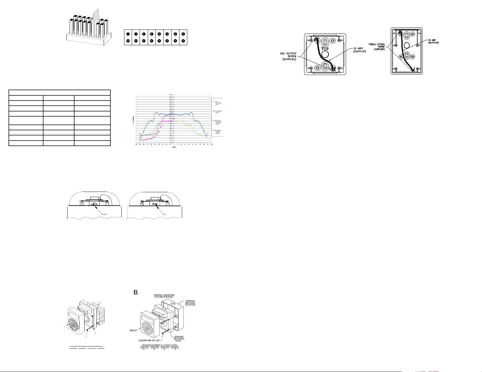
NOTE: Speaker-strobe mounting depicted above. For non-strobe speaker surface mounting, use E50SB:
NOTE: Surface backbox (E50SSB) in Figure B, is compatible with wiremold and conduit. Mounting holes are for single-gang, double-gang,
and #10 wood screws for stud mounting. If metal conduit is installed onto top and bottom conduit entrances, then an insulated grounding
wire (18 AWG, supplied) must be connected between the top and bottom plate by using thread cutting screws (supplied) to provide electrical
continuity per UL 50. See Figure 6.
Figure 6: Surface Backbox E50SB (left) and E50SSB (right)
MOUNTING PROCEDURES
CAUTION: Check that the installed product will have sufficient clearance and wiring room prior to installing backboxes and conduit, especially
if sheathed multiconductor cable or 3/4” conduit fittings are used.
E50H models have an integrated Speaker Mounting Plate.1.
The Speaker Mounting Plate must be oriented correctly when it is mounted to the backbox. Turn the Speaker Mounting Plate so that the2.
arrow above the words “Horizontal Strobe” points to the top side of the Speaker Mounting Plate.
First mount the Speaker Mounting Plate to the backbox. Next slide the grille over the Speaker Mounting Plate strobe until both snaps are3.
engaged.
When terminating field wires, do not use more lead length than required. Excess lead length could result in insufficient wiring space for4.
the signaling appliance.
Conduit entrances to the backbox should be selected to provide sufficient wiring clearance for the installed product.5.
Do not pass additional wires (used for other than the signaling appliance) through the backbox. Such additional wires could result in6.
insufficient wiring space for the signaling appliance.
Mounting hardware for each mounting option is supplied.7.
All models can be flush mounted to a 4” square by 2-1/8” deep backbox in the wall (Figure A).8.
Use care and proper techniques to position the field wires in the backbox so that they use minimum space and produce minimum stress9.
on the product. This is especially important for stiff, heavy gauge wires and wires with thick insulation or sheathing.
Use care to prevent speaker cone damage when driving screws for speaker product mounting.10.
WARNING: When installing strobes in an open office or other areas containing partitions or other viewing obstructions, special atten-
tion should be given to the location of the strobes so that their operating effect can be seen by all intended viewers, with the intesity,
number, and illumination, regardless of the viewer’s orientation.
The 110cd and 135/185cd settings are Listed for use in sleeping or non-sleeping areas when installed in accordance with appropriate NFPA
Standards and the Authority Having Jurisdiction.
WARNING: Installers must advise owners and operators of buildings with sleeping occupants, e.g., hotels and motels, to warn
guests, residents and employees to not move the bed location to a position violating points (1) and (2) above or serious injury and or
loss of life may occur during a fire emergency.
WARNING: A small possibility exists that the use of multiple strobes within a person’s field of view, under certain circumstances,
might induce a photo-sensitive response in persons with epilepsy. Strobe reflections in a glass or mirrored surface might also induce
such a response. To minimize this possible hazard, cooper wheelock strongly recommends that the strobes installed should not pres-
ent a composite flash rate in the field of view which exceeds five (5) hz at the operating voltage of the strobes. Cooper wheelock also
strongly recommends that the intensity and composite flash rate of installed strobes comply with levels established by applicable
laws, standards, regulations, codes and guidelines.
If this appliance is required to produce a distinctive three-pulse Temporal Pattern Fire Alarm Evacuation Signal (for total evacuation) in ac-
cordance with NFPA 72, the appliance must be used with a fire alarm control unit that can generate the temporal pattern signal. Refer to
manufacturer’s installation manual for details.
NOTE: NFPA 72/ANSI 117.1 conforms to ADAAG Equivalent Facilitation Guidelines in using fewer, higher intensity strobes within the same
protected area.
CAUTION: Check the installation instructions of the manufacturers of other equipment used in the system for any guidelines or restrictions on
wiring and/or locating Notification Appliance Circuits (NAC) and notification appliances. Some system communication circuits and/or audio
circuits, for example, may require special precautions to assure electrical noise immunity (e.g., audio crosstalk).
NOTE: This equipment has been tested and found to comply with the limits for a Class A digital device, pursuant to part 15 of the FCC Rules.
These limits are designed to provide reasonable protection against harmful interference when the equipment is operated in a commercial
environment. This equipment generates, uses, and can radiate radio frequency energy and, if not installed and used in accordance with the in-
struction manual, may cause harmful interference to radio communications. Operation of this equipment in a residential area is likely to cause
harmful interference in which case the user will be required to correct the interference at his own expense.
This Class A digital apparatus meets all requirements of the Canadian Interference-Causing Equipment Regulations.
Cet appareil numérique de la classe A respecte toutes les exigences du Réglement sur le matériel brouilleur du Canada.
ANY MATERIAL EXTRAPOLATED FROM THIS DOCUMENT OR FROM COOPER WHEELOCK MANUALS OR OTHER DOCUMENTS DE-
SCRIBING THE PRODUCT FOR USE IN PROMOTIONAL OR ADVERTISING CLAIMS, OR FOR ANY OTHER USE, INCLUDING DESCRIPTION
OF THE PRODUCT’S APPLICATION, OPERATION, INSTALLATION AND TESTING IS USED AT THE SOLE RISK OF THE USER AND COOPER
WHEELOCK WILL NOT HAVE ANY LIABILITY FOR SUCH USE.
5/12

This manual suits for next models

6

Other Cooper Notification Security System manuals

Cooper Notification RSS Series User manual

Cooper Notification

Cooper Notification RSS Series User manual

Cooper Notification UTA-1 User manual

Cooper Notification

Cooper Notification UTA-1 User manual

Popular Security System manuals by other brands

Raco Guard-It owner's manual

Raco

Raco Guard-It owner's manual

Motoman XRC Maintenance manual

Motoman

Motoman XRC Maintenance manual

Carmanah G Series Guide

Carmanah

Carmanah G Series Guide

DSC Power432 PC585 instruction manual

DSC

DSC Power432 PC585 instruction manual

CADDX Ranger 8000 installation manual

CADDX

CADDX Ranger 8000 installation manual

WJG 530-095 Reference manual

WJG

WJG 530-095 Reference manual

American Dynamics Intellex DV16000 Installation and operating instructions

American Dynamics

American Dynamics Intellex DV16000 Installation and operating instructions

Comtronics 246550 installation instructions

Comtronics

Comtronics 246550 installation instructions

Utilitech UT-6168 installation instructions

Utilitech

Utilitech UT-6168 installation instructions

Reliance Controls The Home Protectors 11034 Installation and operating instructions

Reliance Controls

Reliance Controls The Home Protectors 11034 Installation and operating instructions

SkyLink SA-103A Preliminary manual

SkyLink

SkyLink SA-103A Preliminary manual

Honeywell 032211.17 manual

Honeywell

Honeywell 032211.17 manual

ADT L5000 Lynx Battery instructions

ADT

ADT L5000 Lynx Battery instructions

CrucialTrak BACS Tube Quick user guide

CrucialTrak

CrucialTrak BACS Tube Quick user guide

Extech Instruments 445814 user guide

Extech Instruments

Extech Instruments 445814 user guide

SecurityMan AIR-ALARM II SERIES user manual

SecurityMan

SecurityMan AIR-ALARM II SERIES user manual

Stahl 6161 Series operating instructions

Stahl

Stahl 6161 Series operating instructions

Beeper XRAY XR2 Installation and user manual

Beeper

Beeper XRAY XR2 Installation and user manual

manuals.online logo
manuals.online logoBrands
  • About & Mission
  • Contact us
  • Privacy Policy
  • Terms and Conditions

Copyright 2025 Manuals.Online. All Rights Reserved.