Multi-COM MC5P User guide

MULTICOM 5 PLUS INSTALLER MANUAL 24
© Copyright Aug 2013
* Inteliswitch is Patent Pending
Document Version 1.9
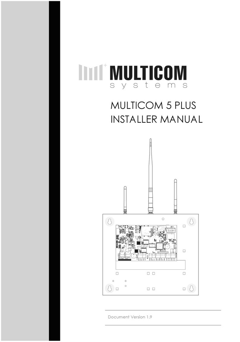
MULTICOM 5 PLUS
INSTALLER MANUAL

MULTICOM 5 PLUS INSTALLER MANUAL 2
Table of Contents
Table of Contents ................................................................................................................................ 2
Features ............................................................................................................................................... 3
Product Features ............................................................................................................................ 3
ComWatch Feature (Patent Pending) ........................................................................................ 3
Technical Features ......................................................................................................................... 4
Quick Start Guide ............................................................................................................................... 5
Hardware Diagram ............................................................................................................................. 8
Hardware Descriptions ....................................................................................................................... 9
Pairing the Multicom Inteliswitch* ................................................................................................... 11
Panel Programming Methods .......................................................................................................... 12
Multicom TechTools App ............................................................................................................. 12
Download & Register ............................................................................................................ 12
Log On to the Device ............................................................................................................ 12
Programming the Device ..................................................................................................... 13
Commissioning the Device ................................................................................................... 13
DTMF using a Phone Handset/Butt ............................................................................................ 14
SMS using a GSM mobile device ............................................................................................... 14
Programming Options ...................................................................................................................... 15
Event Description .............................................................................................................................. 19
Defaults ......................................................................................................................................... 19
Fault outputs ................................................................................................................................. 19
CID Event Map .................................................................................................................................. 20
Appendix A ....................................................................................................................................... 21
Limited Warranty Statement ............................................................................................................ 22
MULTICOM 5 PLUS INSTALLER MANUAL 23
Multicom does not install or connect the products, which may be used in conjunction with other
products not manufactured by Multicom; therefore Multicom cannot guarantee or warrant the
performance of the security system. Multicom will not be responsible for circumstances resulting from
the product’s inability to operate. Your security system should be considered as one of many tools
available to reduce risk and/or damage caused by burglary, fire or other emergencies. Other tools
include, but are not limited to, access controls, lock products, insurance coverage, fire prevention, fire
extinguishing devices and sprinkler systems. We strongly recommend that your security alarm system be
tested and maintained on a regular basis, and that you stay aware of new and improved Multicom
products and developments.
BEWARE: Dealers, installers and/or others selling, distributing or advertising Multicom product(s) are not
authorised to modify this warranty or make any additional warranties that are binding on Multicom or
distributors and its affiliates without the written approval from Multicom.
Multicom may change the terms of its limited warranty, without notice, at its discretion.
WARNING: Due to limitations of Alarm Systems, Multicom cannot guarantee the performance of the
security system and shall not be responsible for circumstances resulting from the product's inability to
operate. It must be understood that while your Multicom product is highly advanced and secure, it only
forms part of your total security installation and it does not offer any guaranteed protection against
burglary, fire or other emergency. This is due to a number of reasons, including, but not limited to,
inadequate or improper installation/positioning, sensor limitations, battery performance, wireless signal
interruption, inadequate maintenance, or the potential for communication mediums to be
compromised or circumvented. As a result, Multicom does not represent that the alarm system will
prevent personal injury or property damage, or in all cases provide adequate warning or protection.
Your security system should therefore be considered as one of many tools available to reduce risk
and/or damage of burglary, fire or other emergencies; such other tools include, but are not limited to
insurance coverage, fire prevention and extinguisher devices, and sprinkler systems. We also strongly
recommend you to regularly maintain your security systems and stay aware of new and improved
Multicom products and developments. For those customers who are using a security system connected
to a non-traditional telephone system, such as "Voice Over Internet Protocol" (VoIP) that converts the
voice signal from your telephone to a digital signal travelling over the Internet, you should be aware
that your alarm system may not function as effectively as with traditional telephone systems. For
example, if your VoIP equipment has no battery back-up, during a power failure your system's ability to
transmit signals to the central station may be compromised. Or, if your VoIP connection becomes
disabled, your telephone line monitoring feature may also be compromised. Other concerns would
include, without limitation, Internet connection failures, which may be more frequent than regular
telephone line outages. We therefore strongly recommend that you discuss these and other limitations
involved with operating an alarm system on a VoIP or other non-traditional telephone system with your
installation company. They should be able to offer or recommend measures to reduce the risks involved
and give you a better understanding. The Multicom range of communication products are designed to
detect all communication failures within the network and are designed to work effectively around
traditional telephone systems in addition to Non-Traditional Telephony such as VoIP, GPRS, 3G and new
communication mediums including the (NBN) National Broadband Network.

MULTICOM 5 PLUS INSTALLER MANUAL 22
Limited Warranty Statement
Multicom Systems (henceforth known as Multicom) warrants its products to be free from defects in
material and workmanship, under normal use, for a period of twelve (12) months, or twenty four (24)
months if the Multicom product is installed by a ‘Certified Multicom Installer’, from the date of
purchase. If the warranted products are returned to Multicom during this period of coverage, Multicom
will repair or replace (at its discretion) without charge, those items found to be defective. Any
replacement or repaired parts are warranted for the remainder of the original warranty or ninety (90)
days, whichever is longer. The original purchaser must promptly notify their Multicom distributor, in
writing during the warranty period, that there is a defect in material or workmanship. All Multicom
distributors and dealers have a warranty program and you are expected to return your product with
proof of purchase in accordance with such a program. Prior authorisation is required before returning
the product, as Multicom will not accept any shipment for which prior authorisation was not first
obtained. Multicom will, at its option, repair or replace without charge, those authorised returned items
it finds defective.
Please note that this warranty does not cover any software products, which are licensed under terms of
a separate software license agreement included with the product purchased. This warranty only
applies to defects in parts relating to Multicom products identified with a Multicom product label and
shall not cover transformers, metal boxes, access cards & tags, batteries, tamper kits, spare parts,
cables & connectors, temperature sensors, promotional items & displays freight, and labour.
This warranty does not cover damage incurred in shipping or handling, problems that result from
external causes such as accident, abuse, and misuse, or problems with electrical power failures, or
other damage caused by:
5. peripherals or unauthorised alterations or modifications;
6. servicing not authorised by a Multicom Certified Professional;
7. usage that is not in accordance with product instructions;
8. using accessories, parts or components not supplied or recommended by Multicom;
9. failure to provide a suitable installation environment for the products;
10. failure to change passwords, settings and/or pin codes from factory default and;
11. improper maintenance or failure to perform regular preventative maintenance
Multicom’s responsibility for defects in material is limited to repair and replacement of the product.
Multicom does not accept liability beyond the remedies provided for in this limited warranty or for any
special, indirect, consequential or incidental damages, including without limitation, any liability for third
party claims against you for damages. Multicom’s maximum liability will be no more than the amount
paid for the product that is the subject of the claim. The laws of some jurisdictions do not allow the
disclaimer of consequential damages. Under such circumstances, the limitations and disclaimers herein
shall be to the greatest extent permitted by law.
This warranty contains the entire warranty and shall be in lieu of any and all other warranties, whether
express or implied, including without limitation, implied warranties and conditions of merchantability
and fitness for a particular purpose, statutory or otherwise. This disclaimer of warranties and limited
warranty is governed by the laws of the New South Wales, Australia.
Multicom will not be responsible for any custom fees, or taxes that may be due. For those jurisdictions
where the legal minimum warranty exceeds the Multicom warranty period, this warranty will be equally
extended to meet such legal minimum requirement.
MULTICOM 5 PLUS INSTALLER MANUAL 3
Features
Product Features
• 5 paths of communications
o GPRS
o Contact ID via GSM
o Contact ID via PSTN
o Ethernet
o PFP (Poll fail protocol via
the GSM network)
• 6 Paths for programming options
o SMS
o PSTN (Attach standard
hand set and program
via DTMF tones)
o Serial converter (to
terminal or Multicom
Configuration Tool)
o Bluetooth*
o GPRS via Surepoll
Network
o Ethernet via Surepoll
Network
• PSTN Line failure detection based
on time and line voltage
threshold (both programmable)
• ComWatch allows the Multicom
to monitor, detect and report
failure to communicate alarm
messages via PSTN/GSM even if
voltage is present Ref Option 5,
12 and 37.
• PSTN switch over time
programmable (300mS default)
• AC failure detection
• Battery under/over voltage
detection
• Programmable alarm path
priority.
• Four Zone inputs (EOLR), each
zone can be disabled or
enabled.
• The alarm panel attached can
be routed either via MC5P as
priority (GPRS Priority), or, Direct
to PSTN (If PSTN line voltage is
available, the alarm can
communicate directly).
• Dedicated local tamper input
• Fault reports for GSM, PSTN, ETH,
GPRS, AC fail, Batt Fail, Zones
and Tamper. Each group of
alarm events can be mapped to
either/or Relay and Contact ID
• Optional AES Encryption for all
polling and alarm data sent via
GPRS or Ethernet (required for
class 4/5)
• Programmable Test report time
• Programmable Contact ID client
code, Primary monitoring station
number and optional PBX prefix
for PSTN dialling.
• Programmable Relay outputs
(Timed and latched functions via
SMS, GPRS, Ethernet or Serial
interface)
• Full RSU (Remote Software
Update) via GPRS, Ethernet or
local Serial Port.
• 12V Auxiliary output (200mA)
• Backup battery with 3 stage
microprocessor controlled
charger
ComWatch Feature (Patent Pending)
The Multicom does more than just monitor the PSTN line voltage or GSM network connection
to detect and report a fault. The Multicom monitors the actual alarm delivery and CMS
Receiver kiss off to ensure the communication was successful and the PSTN path is validating
alarm messages correctly. ComWatch has the advantage of detecting the following faults
that cause Contact ID alarm delivery failures and delivers them via:
• Line voltage being present but not connecting to the monitoring centre
• Dialling the CMS number(s) but getting engaged / congestion
• Phone bill on premise not paid: voltage and dial tone is present but outbound calls
blocked
• Network interconnection faults or terminating number errors
• 13XX call baring
• CMS Receiver Failures

MULTICOM 5 PLUS INSTALLER MANUAL 4
Technical Features
• Freescale 80Mips 32 bit processor
• Multithreaded Real Time
Operating system for seamless
real time path recovery and
system resource management
• Telit GC864 Quad band GPRS
modem
• 2 RJ11 connections for phone
line in / out with Mode 3 and
Isolation relays built in
• 10/100MB FEC (Fast Ethernet
Controller) with DHCP, Static IP,
UDP control.
• Tri-state SLA battery charger for
ideal battery charge control
(Float charge, trickle charge and
fast charge)
• Customizable I/O for interfacing
to various external interfaces
• Expander options for custom
peripheral interfacing
• Terminal interface for
debugging, programming,
monitoring, configuring system
options
• System powered by standard
16Vac, 50Hz, 1.5Amp plug pack
• Serial Shell interface for simple
local programming using a
standard USB-to-serial cable and
• All alarm communication paths
have priority assignment for
alarm event communication
• Bluetooth module on board for
local connections*
MULTICOM 5 PLUS INSTALLER MANUAL 21
Appendix A
Quick Trouble shooting guide
Question Answer
The "COMM" led flash's slowly indefinitely and
stops occasionally
This would generally indicate that GSM has
not been able to connect to the network,
check the antenna connections and a valid
SIM card is installed
The GSM Signal LED's flash on and off GPRS has not been able to establish a
connection on the private WAN, ensure a
valid SIM is installed.
The GSM Signal LED's are on solid but the
"COMM" LED flash's slowly
Ethernet has not been able to connect to
the server. Check you option settings in
55/59, ensure that the ports 5000-5010 are
allows on the local firewall, ensure the Green
and Orange LED's are on where you connect
the Ethernet cable (RJ45 socket).
"COMM" led is on, GSM signal LED's are ok,
the fault LED is always on
Check all zones that are enabled (Option 30)
are sealed with the correct end of line
resistors, the tamper is closed, the battery is
connected, AC is connected and a PSTN line
is connected (is enabled)

MULTICOM 5 PLUS INSTALLER MANUAL 20
CID Event Map
You will need to have your monitoring station map the following events for the account (Fax
this list) if Multicom is not already in their Contact ID list. IMPORTANT NOTE: The MC5P will send
'pending alarms' (Event type 6) with test reports, you may need to include pending alarm
notifications to come to the operator. X = Event, Restore or Previous Alarm (E,R or P)
Event Description CID Offset (Zone)
Tamper External Tamper Triggered 18X95099900
Zone 1 Zone 1 Triggered 18X95099901
Zone 2 Zone 2 Triggered 18X95099902
Zone 3 Zone 3 Triggered 18X95099903
Zone 4 Zone 4 Triggered 18X95099904
PSTN Fault
Alarm
PSTN voltage has been lower than the
programmed voltage for the programmed time
18X95099905
Battery Fault
Alarm
The battery voltage has been outside 'normal
operating limits' for the programmed period of time
18X95099906
GSM Fault
Alarm
GSM has not been connected to the network for
the programmed period of time
18X95099907
GPRS Fault
Alarm
GPRS has been unable to communicate with the
servers for the programmed period of time
18X95099908
Eth Fault alarm Ethernet has been unable to communicate with
the servers for the programmed period of time
18X95099909
AC power Fault AC has not been detected for the programmed
period of time
18X95099910
Test Report Test report occurs at the programmed interval 18X95099911
Poll Alarm Unable to poll for the programmed period of time 18X95099912
PGM Update Remote software update 18X95099913
Alarm buffer
Overflow
The MC5P has previously had to many contact ID
alarms in its buffer, some alarms have been lost
18X95099914
COMM's Failure Multicom was previously unable to communicate
some alarm events
18X95099915
Service
Required
Contact your supplier for servicing requirements. 18X95099916
Zone Lock out One or more zones has repeatedly been triggering
in a short period of time, this will lock out the event
until the zone stops repeatedly triggering.
18X95099917
Multicom Power
Point
Notification
This notification report occurs when the MC5P starts
power cycling the Multicom Power Point. It will
restore once Ethernet is restored.
18X95099918
ComWatch Fail Alarm panel has been unable to deliever contact
ID alarms via the standard PSTN/GSM path directly,
the Multicom is now the priority path (Ref Opt 5, 12
and 37).
18X95099920
MULTICOM 5 PLUS INSTALLER MANUAL 5
Quick Start Guide
The following gives an overview of the basic installation steps.
Further details on programming options and methods can be found
in the proceeding sections of the manual.
1. Connect the three antennas to the panel.
1. RF Automation Transmitter – Smallest Antenna
2. GSM – Largest Antenna
3. Bluetooth - Medium Antenna
STEP 2 & 3 IMPORTANT FOR PANEL PLACEMENT
2. Connect the battery terminal block to the corresponding
pins on the PCB. Place the battery on the floor of the
panel and connect the positive (red) and negative
(black) battery leads to the corresponding terminals on
the battery.
3. Test the GSM signal in the desired mounting location by
holding it against the wall and observing the signal
strength. The signal must be 2 bars or greater for
operation. Once test is complete remove the battery
terminal block and leave disconnected for the following
steps.
4. Mount the panel to the desired location. Use the
provided mounting template to locate screw holes and
establish antenna clearance.

MULTICOM 5 PLUS INSTALLER MANUAL 6
5. Connect the PANEL socket directly to the
alarm panel’s dialler output using an RJ12
cable. If PSTN will be used as a
communication path, connect the PSTN
socket to a standard PSTN phone outlet.
Note: If you are NOT using PSTN, you must
disable the PSTN fault detection (option 39 =
00110000).
6. Connect the Ethernet to the local network, if
Ethernet will be used as a communication path,
using a patch cable. If the local network does
not use a DHCP server, you will need to
organise the static IP settings (IP address for
Multicom, Subnet Mask and Gateway). Consult
the site IT Administrator for further details.
See programming options (page 15) 55 to 59 to
enable and configure the Multicom to suit your
network.
7. Connect the local Internet modem/router into the
provided Multicom Inteliswitch*, if Ethernet will be
used as a communication path. This allows the
Multicom to remotely reset network devices during
prolonged network outages in an attempt to recover
network connectivity. To confirm operation press the
AUX button on the MC5P and ensure the Inteliswitch
power cycles.
The Inteliswitch will come pre-learnt to your panel but
if you have issues or want to control more Inteliswitch devices from your panel
please consult Pairing the Multicom Inteliswitch (Page 11).
8. Interconnect Alarm Panel Relay Output
Relay/COM: To allow immediate notification of
communication failure to the control room, program
one of the alarm panel’s relay outputs to trigger
immediately on PSTN/COMM fail. Connect the alarm
panel’s relay output to one of the Multicom’s Zone
Inputs then ensure that the zone is enabled. See
Option 30.
If the Multicom is behind a
firewall, it is important to ensure
inbound/outbound UDP ports
5000 to 5010 are open.
Note: Steps 8 & 9 are required to meet Class 4 and
up of the Australian Standard.
MULTICOM 5 PLUS INSTALLER MANUAL 19
Event Description
Defaults
Event Fault LED Fault Relay
Default
Contact ID
Reporting
Fault relay and
Contact ID delay
AC Instant Relay 1 Enabled 15 minutes
Battery Instant Relay 1 Enabled 10 minutes
Tamper Instant Relay 1 Enabled Instant
Zone 1 Disabled Relay 1 Disabled
Zone 2 Disabled Relay 1 Disabled
Zone 3 Disabled Relay 1 Disabled
Zone 4 Disabled Relay 1 Disabled
Zone
Lockout
NA Not Mapped Enabled
GSM Instant Relay 2 Disabled
GPRS Instant Relay 2 Disabled
Ethernet Instant (Disabled by Default) Relay 2 Disabled
PSTN Instant Relay 2 Enabled 30 seconds
Multicom
Power
Cycle
Notification
NA RF
Transmitter
Enabled 10 minutes
Poll Fail NA Relay 2 Disabled 90 seconds
ComWatch Instant Relay 2 Enabled Option 5
Fault outputs
There are four mapping options for the 2 on board relays:
1. Not Mapped - The relays are able to be remotely controlled via SMS, Ethernet,
GPRS, Serial, or Bluetooth.
2. Communications – Communications has not worked for the programmed period of
time. e.g. If the Multicom is configured to report a PSTN line failure after 60 seconds,
the relay will activate 60 seconds after the PSTN is removed, the Multicom will also
generate an alarm message for PSTN failure. The options for this path are GPRS,
Ethernet and PSTN.
3. External Zone / Tamper - The output will trigger while the Tamper is open, or, any of
the on board zones are not sealed with the appropriate EOLR.
4. Power Fault (AC or battery failure) - The output will trigger if after the programmed
AC / Battery fault time.
Note: Each of the above can be individually disabled in the configuration.

MULTICOM 5 PLUS INSTALLER MANUAL 18
Ethernet Static IP / Default: Blank
SMS E I P : A . B . C . D
DTMF * 5 7 A * B * C * D #
Allows you to configure a static IP for the
Multicom on your local Ethernet network.
Where A.B.C.D is the IP address. Example,
to assign the Multicom to 10.1.1.2 send
EIP:10.1.1.2 or *5710*1*1*2#
Ethernet Subnet Mask / Default: Blank
SMS E S U B : A . B . C . D
DTMF * 5 8 A * B * C * D #
Allows you to configure the Ethernet
Subnet mask for the Multicom. Where
A.B.C.D is the subnet mask. E.g. send
ESUB:255.255.255.0 or *59255*255*255*0#
Ethernet Gateway / Default: Blank
SMS E G A T E : A . B . C . D
DTMF * 5 9 A * B * C * D #
Allows you to configure the Ethernet
gateway for the Multicom.Where A.B.C.D
is the Ethernet internet gateway. E.g, to
assign the Multicom gateway address to
10.1.1.1 send EGATE:10.1.1.1 or =
*5910*1*1*1#
MULTICOM 5 PLUS INSTALLER MANUAL 7
9. Interconnect Multicom Relay Output
Input/COM: To notify the alarm panel of MC5P
communication failure, ensure that one of the MC5P
relays is programmed to “COMM’s fail event” (Relay 1 is
programmed to this by default). Connect the Multicom’s
relay output to one of the Alarm Panel’s Zone Inputs. It is
recommended that the zone on the alarm panel be a 24
hour audible input. See Option 38.
Defaults; Relay 1 is triggered by communication failures,
Relay 2 is triggered when AC/Batt or Zone alarms occur
and remains active until the fault condition is cleared.
10. Panel Arm/Disarm or Output Control (Recommended Option)
Relays 2 to 4 can be configured to arm/disarm the alarm panel or control other
devices such as gates (open & close) etc. This may be used to arm/disarm from
Multicom smartphone apps. See Option 38.
11. Re-connect the AC power pack to the AC terminal block
as shown. Connect the AC and battery terminal block
to the corresponding pins on the PCB. Connect the AC
plug pack to a power outlet and confirm that the
Multicom powers up and LEDs light up.
YOUR MULTICOM MUST HAVE A PERMANENT EARTH
CONNECTION!
12. Commission the panel by completing the commissioning
screen in the TechTools App or calling the Activations
Centre on 1300 603 704. For commissioning via phone
please have the required information ready and notify the
operator that the Multicom panel (MC5P) is connected
and ready for commissioning.
13. Test the installation for correct communications as
required.
Example: If GPRS is the primary path, activate the alarm
panel and ensure the alarm events are received at the
monitoring station. If PSTN is primary, remove the PSTN
connection, activate the alarm and ensure the event is
received at the monitoring station.
14. For configuration issues please consult the Trouble shooting guide in Appendix A

MULTICOM 5 PLUS INSTALLER MANUAL 8
Hardware Diagram
MULTICOM 5 PLUS INSTALLER MANUAL 17
Test report time / Default: 24
SMS 3 1 2 4
DTMF * 3 1 2 4 #
The time between test reports for the
Multicom (in hours), default 24 hours.
Independent of the alarm panel &
Multicom system polling. Test reports are
sent via the primary path.
Contact ID Retry Attempts / Default: 5
SMS 3 2 5
DTMF * 3 2 5 #
How many times to attempt sending a
contact ID message before considering
that path to have failed
GSM Fault Detection Delay / Default: 240
SMS 3 3 2 4 0
DTMF * 3 3 2 4 0 #
How long to wait before detecting GSM
Fault (Seconds). See options 39 for
enabling CID notification.
PSTN Fault Detection Delay / Default: 60
SMS 3 4 6 0
DTMF * 3 4 6 0 #
How long to wait before detecting PSTN
Communication Fault (60 Seconds
default). This also trips the FAULT Relay (See
39 for relay map). See options 39 for
enabling CID notification.
Ethernet Fault Detection Delay / Default: 240
SMS 3 5 2 4 0
DTMF * 3 5 2 4 0 #
How long to wait before detecting
Ethernet Fault (Seconds). See options 39
for enabling CID notification.
Relay mapping/ Default: 122
SMS 3 8 A B C
DTMF * 3 8 A B C #
ABC, where A = COMM's fail event, B =
Aux alarm event (Batt + AC), C = External
alarm (Zone1-4 and tamper). Each event
can be mapped to 0 = Not Mapped,
1 = Relay 1, 2 = Relay 2.
Contact ID Event enable/disable / Default:1
SMS 3 9 A B C D E F G H
DTMF * 3 9 A B C D E F G H #
To disable Event set to 0, to enable set to
1. Default is all zones enabled. Zones are
all 24 hour zones.
Where:
A = Multicom Power Point Power Cycle
Notification
B = Poll Fail
C = AC Fault
D = Batt Fault
E = PSTN Fault
F = Ethernet fault
G = GPRS Fault
H = GSM Fault
Ethernet Enable / Disable / Default: 0
SMS E T H : O N
DTMF * 5 5 0 #
Allows you to enable / disable Ethernet as
a polling path. 1 to enable, 0 to disable.
Ethernet DHCP Enable / Disable / Default: 1
SMS D H C P : O N
DTMF * 5 6 1 #
Allows you to configure the Ethernet as
either Static or DHCP. When DHCP is
disabled, you must configure a static IP. 1
to enable DHCP, or 0 to disable via PSTN.

MULTICOM 5 PLUS INSTALLER MANUAL 16
User Password / Default: user
SMS 1 6 u s e r
This is the access password for serial and
Bluetooth interfaces. This can not be
programmed via PSTN.
PSTN Fault Threshold (Volts) / Default: 3
SMS 1 7 0 3
DTMF * 1 7 0 3 #
Voltage to detect line failure at (3V
default)
Contact ID Retry Delay / Default: 15
SMS 1 8 1 5
DTMF * 1 8 1 5 #
Time delay between Contact ID retries (in
seconds), time is based on the start of
dialling, default 15 seconds.
CID Base message / Default: 18095099900
SMS 2 0 X X X X X X X X X X
DTMF * 2 0 X X X X X X X X X X #
This is the default base Contact ID
message, refer to the format template
table for individual alarms.
Line Fault Switch Delay / Default: 300
SMS 2 5 3 0 0
DTMF * 2 5 3 0 0 #
Switching delay for the Mode3 Relays on
failure restore (in milliseconds), Default
300mS. This must be very quick, as the
MC5P will connect directly to the
attached panel to take control of the
communications.
Poll Fail Detection Delay / Default: 150
SMS 2 6 1 5 0
DTMF * 2 6 1 5 0 #
This monitors all paths for polling within the
programmed time; this is mapped to the
relays. Default 150 seconds. See option 38
for relay map. See option 39 for enabling
CID notification.
Battery Fault Detection Delay / Default: 10
SMS 2 8 1 0
DTMF * 2 8 1 0 #
Delay before reporting backup battery
fault (minutes). This is also used as AUX trip
for fault relays, see option 38 for relay
map. See options 39 for enabling CID
notification.
AC Fault Detection Delay / Default: 15
SMS 2 9 1 5
DTMF * 2 9 1 5 #
Delay before reporting AC failure (in
minutes) Default 15 minutes. This is
mapped to the fault relays, see 38. See
options 39 for enabling CID notification.
Zone enable / Disable / Default: 0000
ZONE
4 3 2 1
SMS 3 0 0 0 0 0
DTMF * 3 0 0 0 0 0 #
To disable zones set to zero, to enable set
to one. Default is all zones disabled. Zones
are all 24 hour zones. These are mapped
to fault relays by option 38.
MULTICOM 5 PLUS INSTALLER MANUAL 9
Hardware Descriptions
1) MODE3 LOOPED When this LED is active,
the PSTN connects the Mode 3
connections. When this LED is inactive, the
Mode 3 connections are passed from PSTN
to PANEL.
2) PSTN Connects to standard PSTN.
3) ISOLATE When this LED is active, the
Alarm Panel is not connected to PSTN, it is
connected to the Multicom only.
When this LED is inactive, the Alarm Panel
is connected to PSTN.
4) PANEL Connects to the Alarm Panel or
other communications device.
5) AC1 and AC2 The Multicom is powered
by 16Vac 1 Amp power supply.
6) +BATT and –BATT Connect a standard
12V Sealed Lead Acid type battery. The
Multicom has a tri-state charger designed
to help optimize battery life and
performance.
7) PROG1 & PROG2 Custom interfaces may
be incorporated to the Multicom using
these pins. Please contact your supplier
for specialist interface requirements. There
are several thermal sensors, data
interfaces which can be interfaced with
for local / remote monitoring.
8) 12V & GND Auxiliary 12V power can be
taken from these pins. The load must not
exceed 200mA. This output has a
resettable fuse, which will automatically
reset once any overload condition is
removed.
9) ZONE1, ZONE2, ZONE3 & ZONE4 Each
zone requires a 3K3 End Of Line resistor to
be 'sealed'. All zones operate as 24hour
alarm inputs & are not enabled by default.
10) R1COM, R1 NC, R1 NO Relay 1 is
programmed as a communications fault
relay. If there is no communication path
available for longer than the pre
programmed time this will active until
communications are restored.
11) R2COM, R2 NC, R2 NO Relay 2 is
programmed as an alarm output. This will
activate when an alarm condition is
active on the MC5P (Zone, AC Fail, Batt
Fail, Tamper active)
Note: Either relay can be programmed to
be remotely activated for remote
arm/disarm or other access control
functions. Each relay can also have
specific events trigger the relay
12) TAMPER Connect to the case tamper,
this circuit requires a normally closed
tamper (no EOLR required)
13) SERIAL Allows for configuration and
analysis of the Multicom. This requires a
MPC-cable and the PC Multicom Analysis
Tool Software.
14) ETHERNET Connect the Multicom's
Ethernet socket to any spare Ethernet port
on the site's network, which will allow
access to the Internet. Some networks
(firewalls/gateways) may require port 5000
to 5010 (TCP & UDP) be opened on the
internet gateway device. By default, you
will require DHCP to be enabled on the
network, contact the sites IT support staff
for configuration requirements.
15) BLUETOOTH Allows for wireless
configuration and analysis of the
Multicom. The Bluetooth interface can be
used with the Multicom Analysis Tool
software on a PC with an inbuilt or USB
dongle Bluetooth device.
16) SIM CARD A Surepoll enabled sim card
must be installed for GPRS/GSM operation.
17) GSM/GPRS The GSM / GPRS Antenna
must be installed. For reliable operation
there must be at least 2 bars of signal at
the time of commissioning. The system
may work on one bar however this is not
an acceptable level.

MULTICOM 5 PLUS INSTALLER MANUAL 10
18) GSM/GPRS SIGNAL LED
SOLID - When GPRS is connected
to the server via the private WAN,
the signal LED's will statically show
the signal strength, the signal must
be 2 or greater for reliable
operation.
OFF - The Signal LED's are off during
network connection or rebooting.
FLASHING SLOW - When registered
on the GSM network only, the
signal strength LED's will turn on and
off periodically to indicate GSM is
connected, and GPRS is not
connected.
19) COMMS LED
SOLID - All programmed
communication paths are
'connected' to the server as normal
FLASHING FAST - Path is
communicating
(GSM/GPRS/ETHERNET)
FLASHING SLOW - Path is
establishing or re-establishing
communications
OFF - ERROR (with GSM/GPRS or
Ethernet)
ONE QUICK FLASH PER SECOND -
Remote software update in
progress
20) PSTN LED
SOLID - PSTN line voltage detected
FLASHING FAST - Communicating
with attached alarm panel (or
sending alarms via GSM)
FLASHING SLOW - Path is initializing
the line interfaces, flashing for
longer than 1 second indicates an
error.
OFF - PSTN Line voltage not
detected
21) CHARGE STATE LED
SOLID - Trickle Charge
FLASHING FAST - Fast charge
FLASHING SLOW - Slow charge
OFF - No battery currently
detected or establishing charge
requirements
22) FAULT LED
SOLID - Fault (GPRS poll timeout,
ETH poll timeout, AC Fail, Batt Fail,
Zone open, PSTN Fail, Tamper)
OFF - No fault detected, everything
is 'ok'
23) POWER LED
SOLID – Indicates power is
detected
OFF – No power detected
24) AUX RF LEARN
PGM Pressing PGM button for 5
seconds activates learn mode.
Pressing PGM button momentarily
toggles the Inteliswitch on and off.
AUX LED Flashes during
communication to the wireless
devices.
25) AUX RF TRANSMITTER
AUX Transmitter is a 433Mhz antenna for
communicating to the wireless devices.
The Multicom has a built in 433.925Mhz
transmitter to allow wireless control of
other 433.925Mhz devices. A Multicom
Inteliswitch (433.925 Mhz device) is
provided to allow wireless power cycling
of your modem/router during prolonged
Internet outages. Please contact your
supplier for further details regarding
supported devices.
MULTICOM 5 PLUS INSTALLER MANUAL 15
Programming Options
Account Code / Default: Auto Detect
SMS 0 1 9 9 9 8
DTMF * 0 1 9 9 9 8 #
Contact ID account code used by the 5
Plus Note: Panels that report multiple
account codes may be changed from the
code that was initially taken from the
alarm panel. This option can be changed
during the commissioning procedure with
the Suretek Activations Centre.
Primary CMS Number / Default: Blank
SMS 0 2 1 3 4 5 X X X X
DTMF * 0 2 1 3 4 5 X X X X #
Central Monitoring Station Phone number
for when the Multicom communicates via
GSM or PSTN (Max 19 digits) eg. 13451111
or 1300111222
PBX Prefix / Default: Blank
SMS 1 9 X X X X X
DTMF * 1 9 X X X X X #
Optional number for getting an external
line out via PSTN (not GSM) (Max digits is 5)
Secondary CMS Number / Default: Blank
SMS 3 7 1 3 4 5 X X X X
DTMF * 3 7 1 3 4 5 X X X X #
Program this to the same backup phone
number in the attached panel. This is only
used to allow ComWatch to detect if the
panel is attempting to dial the backup
number, the Multicom will not dial this
number.
ComWatch Mode Count / Default: 3
SMS 0 5 3
DTMF * 0 5 3 #
How many attempts the attached panel
has to correctly deliver a Contact ID
message to the monitoring station before
the Multicom takes priority. Program to 0 to
disable. E.g the panel dials 3 times and no
handshake or kiss off tones are heard, the
Multicom will take control of the alarm
delivery path.
ComWatch Mode Bypass Time / Default: 24
SMS 1 2 2 4
DTMF * 1 2 2 4 #
This is the time in hours that the Multicom
will hold priority after ComWatch detects
that alarms could not be delivered via
PSTN/GSM.
Multicom/PSTN Priority / Default: 1
SMS 1 1 1
DTMF * 1 1 1 #
0 = Multicom is the priority line for the
attached panel, 1 = PSTN is the primary
line for the attached alarm panel.
External Panel Programming Timer /
Default: Blank
SMS 1 3 X X
DTMF * 1 3 X X #
Program this in minutes. This feature allows
bypassing of the Multicom for a
programmed period, so that you can
program an attached panel.

MULTICOM 5 PLUS INSTALLER MANUAL 14
DTMF using a Phone Handset/Butt
1. Connect the Phone butt to the “Panel”
socket. You will hear a dial tone.
2. To enter Program Mode press the * key.
You will hear a busy tone. Enter the
default Program Access Code (1345)
followed by #. When a successful code is
entered you will hear a dial tone. You are
now in the program mode. eg. *1345#.
See Option 40 to change the Program
Access Code.
3. To send a command, follow the Programming Options table, using the DTMF row as a
guide. Commands with PSTN/DTMF are sent using the template:
i. *ADDRESSSETTING# eg. *01ABCD#
ii. Refer to Programming Options table on page 15
4. The Multicom will reply with a dial tone if your option was updated successfully. The
Multicom will reply with a congested/busy tone if an error was encountered.
5. To exit program mode press ##. Your 5 Plus will also automatically exit program
mode after five (5) minutes of inactivity.
SMS using a GSM mobile device
1. To retrieve the Multicom GSM phone number, contact the 24/7 Activations Centre
(1300 603 704 or +61 2 8787 9872) to confirm your identity. After confirmation, the
operator will give you the number, which you can then send SMS commands to.
2. Send an SMS to the device using the template:
ADDRESSSETTING eg. 01ABCD
Refer to Programming Options table on page 15
Sending an SMS containing only +P will result in a SMS response with all programming
options & their current setting.
3. A successful update will result in a SMS response with all programming options and
their current setting.
4. An unsuccessful update will likely not respond.
5. You may also send multiple programming options in one SMS. To do so please
separate each option with a comma(,):
ADDRESSSETTING,ADDRESSSETTING eg. 01ABCD,02ABCD,19ABCD
MULTICOM 5 PLUS INSTALLER MANUAL 11
Pairing the Multicom Inteliswitch*
The following describes how to pair your panel to an Inteliswitch.
1. Plug the Multicom Inteliswitch into a wall outlet and turn on
the power.
2. Press the button on the Multicom Inteliswitch so the blue
LED turns OFF
3. Press the button on the Multicom Inteliswitch until the blue
LED flashes slowly (5 seconds)
4. Press the button on the Multicom Inteliswitch again until the
blue LED flashes quickly (5 seconds)
5. Press the AUX button on the MC5P to learn the
Inteliswitch to the MC5P
6. Test the power point by a quick press on the AUX
button, this will cycle the power (2 seconds off)
NOTE: The Inteliswitch included with your MC5P purchase is paired with your MC5P device
out of the box. This guide is only necessary for adding Inteliswitch devices to your MC5P.

MULTICOM 5 PLUS INSTALLER MANUAL 12
Panel Programming Methods
The following section gives an overview of the 3 programming
methods.
Multicom TechTools App
TechTools is a free smartphone app that configures and commissions Multicom alarm
communicators. TechTools uses a “TechCode” to identify who has access to which
devices.
Download & Register
1. Download the app from iTunes or Google Play Store
Visit http://bit.ly/multicom
2. As an installer you should complete the registration, take note of
your TechCode and give it to your employer(s) who will in turn give
you permission to work on their panels. (Employers may need to
call 1300 65 44 33 to confirm their identity and tie their TechCode
to their Multicom account)
Log On to the Device
1. Click ‘Panels’ on the main screen
2. Enter the ‘Panel ID’ or scan the device barcode (Printed on top of Device &
Packaging) and press ‘Go’.
MULTICOM 5 PLUS INSTALLER MANUAL 13
Programming the Device
1. Once logged on to the device click the ‘Program’ tab.
2. Enter the ‘Program Code’ (Default: 1345) and click OK.
3. You can now edit any available Settings and click ‘Save’ to upload your changes.
Commissioning the Device
1. Once logged on to the device click the ‘Commission’ tab.
2. Enter the ‘Bureau’, ‘Control Room’ and other required reporting details for the
device and press the ‘Activate’ button.
3. Upon successful
commisioning you will
receive the alert
‘Panel has been
activated
successfully’.
Table of contents
Other Multi-COM Security System manuals
Popular Security System manuals by other brands

Apricorn
Apricorn Aegis Secure Key quick start guide

Matelec
Matelec FPC-12651 Operation manual

Visonic
Visonic SR-730 PG2 - installation instructions

Audiovox
Audiovox Prestige Platinum APS-510C owner's manual

ARJAY ENGINEERING
ARJAY ENGINEERING 2852-LPS user manual

Elkron
Elkron CR200 GPRS User, Installation, Programming Manual