6
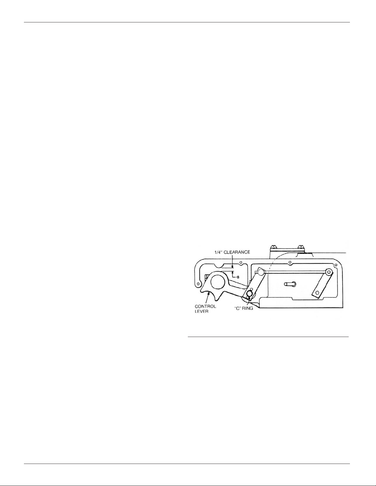
Figure 8.
Overtravel adjustment of control lever.
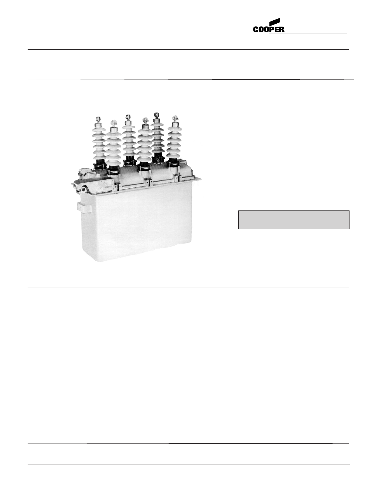
Types RVE and WVE Maintenance Instructions
Insulation Level Withstands Tests
High-potential withstand tests provide information on the
dielectric condition of the recloser. Testing is performed at
75% of the rated low-frequency withstand voltage 52.5 kv.
TEST 1: Proceed as follows:
1. Manually close main contacts of recloser (see page 5 for
procedure).
2. Ground recloser tank and head.
3. Connect all three source-side bushings (1, 3, 5) together.
4. Apply proper test voltage to source-side bushings.
5. The recloser should withstand the test voltage for 60 seconds.
TEST 2: Proceed as follows:
1. Manually close main contacts of the recloser (see page 5
for procedure).
2. Ground recloser tank and head.
3. Ground Phase A (bushing 2) and Phase C (bushing 6).
4. Apply proper test voltage to Phase B (bushing 3).
5. The recloser should withstand the test voltage for 60 seconds.
TEST 3: Proceed as follows:
1. Open main contacts of recloser (see page 5 for procedure).
2. Ground recloser tank and head.
3. Connect and ground all three load-side bushings (2, 4, 6).
4. Connect all three source-side bushings (1, 3, 5).
5. Apply proper test voltage to source-side bushings.
6. The recloser shouId withstand the test voltage for 60 seconds.
7. Reverse the connections: ground source-side bushings (1,
3, 5); apply test voltage to load-side bushings (2, 4, 6) for 60
seconds.
8. The recloser shouId withstand the test voltage for 60 seconds.
TEST RESULTS: These high potential withstand tests provide
information on the dielectric condition of the recloser and the
integrity of the interrupters.
A. If the recloser passes the closed-contacts tests (Tests 1
and 2) but fails the open-contacts test (Test 3) a deteriora-
tion of one or more of the interrupters is likely to be the
cause. Check each interrupter individually to determine the
failed phase or phases, and replace the interrupter(s).
Retest to confirm the repair.
B. If the recloser fails the closed-contacts tests (Test 1 and 2)
the cause is likely to be adiminished electrical clearances,
low oil dielectric strength or failed insulation. After correct-
ing the problem, retest to confirm the repair.
Oil Condition
Oil provides the internal insulation barrier between phases and
from phase to ground, and must be replaced before it deterio-
rates below a safe dielectric level. Replace the oil if its dielec-
tric strength falls below 22 kv.
New oil should always be filtered before use even though it
is obtained from an approved source. Passing the oil through
a blotter press will remove free water and solid contaminants
such as rust, dirt, and lint. Keep aeration to a minimum during
filtering to prevent moisture in the air from condensing in the
oil and lowering its dielectric strength.
Used oiI must be treated before reusing. FiItering may
remove absorbed and free water and other contaminants to
raise the dielectric strength to acceptable levels. However, fil-
tering does not always remove water-absorbing contaminants
and the dielectric strength may fall rapidly after being returned
to service. Therefore the recloser should be filled with new oil,
or oil that has been restored to like-new condition. oil used in
these reclosers conforms to ASTM Standard D3487, Type l; its
property limits are shown in Reference Data R280-90-1, “Oil
Specifications and Tests.”
RATING CHANGES
The continuous current rating and minimum-trip values can be
changed in the field, refer to the control installation manual for
applicable procedures.
Closing coils are available in various voltage ratings from 2.4
to 34.5 kv. There are also three dc closing coils available: 48,125
and 250 vdc. No coil fuses are used with the dc closing coils.
When converting a recloser from a high voltage closing coil to
a low-voltage closing coil a low-voltage contactor and coil kit
(KA887R) is required.
ADJUSTMENTS
Control
Refer to the control installation manual (S280-75-1 ) for applica-
ble procedures for adjusting operations to lockout, reclosing
time, phase-trip sequence, minimum-trip values, resetting time,
ground-trip sequence, phase-trip timing and ground-trip timing.
CONTROL LEVER OVERTRAVEL ADJUSTMENT
Check for proper adjustment of the control lever by first removing
the sleet hood cover to expose the control lever. From the OPEN
position, slowly push the control lever toward the CLOSED posi-
tion. As the lever is pushed up, latching of the recloser will be
felt. At this point the dimension between the top of the control
lever and the underside of the sleet hood should be 1/4 inch
(Figure 8).
If the control lever is not adjusted properly, remove the C-ring
and slide the control lever from the shaft. Rotate the control lever
clockwise to reduce the dimension or counterclockwise to
increase the dimension. Slide the control lever back onto the
shaft and recheck the dimension. When the proper dimension
has been obtained replace the C-ring.
SHOP MAINTENANCE PRODEDURES
The operations described in this section should be performed
under the cleanest conditions possible. The repair work, except
for bushing replacement, will be simplified if the work bench is
arranged so the mechanism/head assembly can be inverted
(bushings down). No special tools are required for any of the
repair procedures.
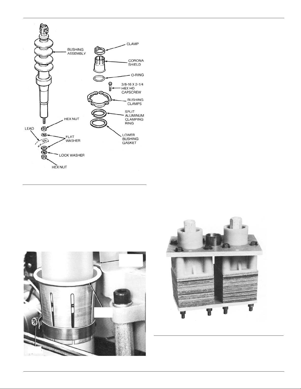
Bushings
Bushing maintenance generally consists of a thorough cleaning
and a careful examination for chips, cracks or other mechanical
damage during the periodic maintenance inspection. Bushings
must be replaced whenever damage is discovered. Refer to
Figure 9 and proceed as follows:
1. Disconnect the bushing lead from the bottom end of the
bushing rod.