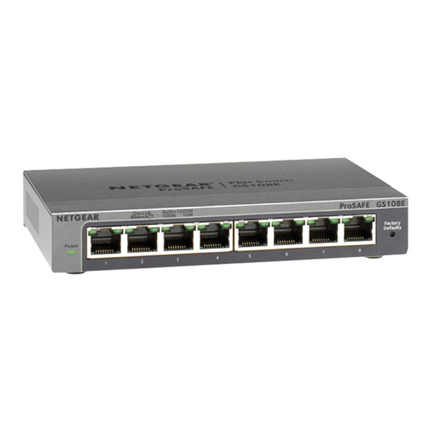
1.3. Buttons to reset the switch
Networking protocols are layer 3. TCP/IP is an example of a networking protocol. Each such protocol
has its own addressing scheme. For example IPv4 uses a 24 bit address expressed by 4 decimal digit
separated by a dot, for example 192.14.134.231. By constrast IPv6 uses a 128 bit address expressed
as eight 16 bit blocks, each block expressed as 4 hex digits with blocks separated by a colon, an example
being FE80:0000:0000:0000:0202:B3FF:FE1E:8329. These addressing schemes are different de-
spite IPv4 and IPv6 both being TCP/IP protocols. Other networking protocols use different addressing
schemes. But each network protocol addressing scheme needs to be converted to, and from, a MAC
address.
The GS724Tv4 switch uses TCP/IP network addressing. In this work IPv4 network addressing only will
be used. The same techniques shown here also apply to IPv6.
Each network element has fixed and changable addesss assignments. The MAC address is fixed in the
hardware. The changable parts are in the software which implements the network protocol such as
TCP/IP. These parts are the address of the device, its network mask, and the gateway to be used by data
to get off the device. Some software implementations require the broadcast address and network ad-
dress to be defined, but these can be calculated from the device address and network mask. The network
address is calculated by applying the AND operation to the address and the netmask combination. The
broadcast address is calculated by applying the OR operation to the combination of the network address
with the bit inverse of the network mask. But contrast, the gateway address must be specified and is to
where a TCP/IP packet is to be sent if the destination to which the packet is addressed cannot be found.
1.2 Switch hardware
The small brown coloured Philips head machine screws supplied with the switch are for attaching the
supplied mounting brackets to the switch housing. Four screw holes threaded for those screws are
provided at both ends of the switch housing.
The larger, chrome plated screws are for attaching the mounting bracket to a mounting frame supplied
by others.
Two mounting brackets in the form of drilled right-angled brackets in a blue colour to match the switch
housing are supplied with the switch.
Power to the switch is through the socket on the back of the switch. A power cable is provided with the
switch for that purpose. No isolating switch for that supply is provided on the switch.
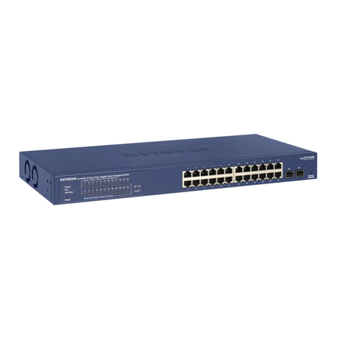
The factory reset button is located on the bottom right of the front housing of the switch. It is recessed
from the surface. Use a straighted paper clip to depress this switch.
1.3 Buttons to reset the switch
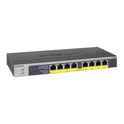
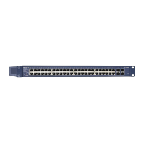
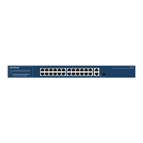
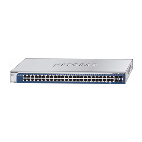
There are two reset buttons on the switch. The Reset button is on the far left-hand side of the face
of the switch while the Factory Defaults button is on the right-hand side of the switch. Both buttons
are resessed from the surface requiring them to be pressed using a straightened paper clip. The switch
acknowledges the button as having been pressed by turning on all of the System LEDs. The reset process
takes two or more minutes to complete. Upon completion of the reset process, the System LEDs are
resturned to indicating the port usage.
The switch documentation states pressing the Factory Defaults button removes any configuration on
the switch and sets the address of the switch to 192.168.0.239. This proved untrue.
2
