Mounting and Operating Manual
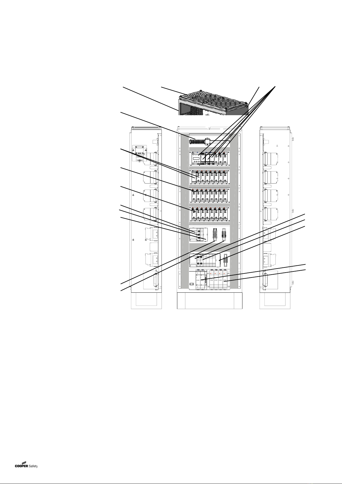
Central Battery System EURO ZB.1
4CEAG Notlichtsysteme GmbH
Mounting work must only be carried
out by skilled electrical personnel (see
IN VDE 0105 Part 1; the Accident Pre-
vention Rules BGV A4 of the (German)
Trade Workers’ Compensation Asso-
ciation (Hauptverband der gewerb-
lichen Berufsgenossenschaften) or
equivalent provisions and guidelines
applicable in the country where the
system is installed and operated).
Other persons may perform the work
described in this manual only if
– they have been expertly instructed
and trained,
– their tasks and activities have been
accurately defined and understood,
– the work is carried out under the su-
pervision of expert electrical person-
nel.
When working with this manual the
following notes provided with attenti-
on-attracting graphical symbols and
identifiers (eg Note) shall be carefully
observed:
Note:
indicates important hints and ad-
vice in connection with handling
or manipulating the appliances or
plant units described.
Attention!
draws attention to dangerous
situations that may result in da-
mage to plants or plant units as
well as environmental hazards.
Warning!
draws attention to dangerous
situations that may result in
personal injuries or major
damage to plants or plant units
as well as major environmental
damage.
Danger!
draws attention to dangerous
situations that may result in life-
threatening personal injuries
or most serious damage that
consequentially may endanger
persons or the environment.
Moreover, when using this mounting
and operating manual observe the
following:
Warning!
The figures and elementary
diagrams in this mounting and
operating manual sometimes
serve the sole purpose of provi-
ding elucidation on the subject
matter described. Wherever
– dimensionally true work is to
be performed or
– precise drawings or circuit
diagrams tailored to local
needs are required,
the drawings and diagrams es-
pecially prepared for the lighting
system must be strictly adhered
to.
Note:
In the event a polyphase ope-
ration is not at all or only con-
ditionally allowed, observance
of the applicable national rules
and regulations is to be viewed
as a prerequisite in the sense of
the Intended Use Paragraph (see
«8 Intended Use»).
Warning!
Only perform work for which you
are adequately qualified and spe-
cifically trained in the framework
of local and operational needs!
Work necessary for extensions,
retrofits or repairs that has not
been described in this manual
must be carried out by specially
trained expert service person-
nel (to be delegated by CEAG
as manufactgurer or sales and
service companies authorized
by CEAG)!
Attention!
When performing work on the
unit ESD protection rules must
be observed!
Attention!
If a reset occurs in battery mode
the failure „battery disconnected“
is shown after the restart.
Important Notes
1Important Notes