Cooper safety BLESSING Atlantic LED Series Instruction manual

Montage en aansluiting:
Dit armatuur is enkel geschikt voor vaste montage en permanente
directe aansluiting op het lichtnet.
Open de benodigde kabelingang in
de onderbak en monteer een wartel.
Gebruik de meegeleverde RVS
schroeven voor montage van de bak.
Houd er rekening mee dat bij
Atlantic LED R vluchtwegverlichting
het meeste licht via de korte zijkanten
wordt uitgestraald, in tegenstelling tot
conventionele fluorescentieverlichting.
Na montage van de onderbak kan de
elektrische aansluiting tot stand worden gebracht:
Atlantic LED decentrale noodverlichting (AT):
N : nul
L1 : ongeschakelde fase
L2 : geschakelde fase
: aarde
Atlantic LED centrale noodverlichting (230-CG):
N + L1: 230 V AC/DC
: aarde
De kabelmantel dient vlak achter de wartel te worden verwijderd. In
verband met de beperkte ruimte dient de bedrading zo kort mogelijk te
worden gehouden en mag deze enkel binnen de aangegeven ruimte
worden gelegd. De verhoging in het midden van de onderbak dient
eveneens vrij gehouden te worden.
Atlantic LED S en D uitvoeringen: Breng eerst een (S) of twee (D)
pictogrammen aan in de kap.
Atlantic LED S: Let bij het aanbrengen
van een pictogram op het verschil tussen
de boven- en onderkant van de kap.
Breng de pictogrammen zorgvuldig aan en controleer of ze achter de
juiste randen zijn opgesloten.
Vervolgens kunnen de kap en de reflector-
plaat worden samengeklikt.
De kap past slechts op één manier op de
reflectorplaat.
Atlantic LED decentrale noodverlichting (AT):
Sluit het batterijsnoer aan op de printplaat.
Atlantic LED centrale noodverlichting (230-CG):
Stel de adresschakelaars als volgt in:
of de positie van de connectoren overeenkomt en plaats vervolgens de
unit in de bak. Draai de 4 inbusbouten voldoende stevig aan.
Testen van Atlantic LED decentrale noodverlichting (AT):
Zodra de netspanning aanwezig is, dient gecontroleerd te worden of de
groene indicatieLED brandt. Het tijdstip waarop de wekelijkse tests
zullen aanvangen, wordt tijdens installatie bepaald door het moment
waarop de batterij-connector op de print wordt aangesloten. Precies
een week na dat moment zal de eerste wekelijkse test (gedurende 2
minuten) worden uitgevoerd. Iedere dertiende week zal een volledige
autonomie-test plaatsvinden. Het verdient aanbeveling het test-tijdstip,
indien mogelijk, te kiezen aan het begin van een periode waarin geen
personen in de ruimte aanwezig zijn. Dit tijdstip kan gewijzigd worden
door de batterij-connector los te nemen en na 5 seconden terug aan te
sluiten. Exact 24 uur na het inschakelen van de netspanning zal een
eerste autonomie-test worden uitgevoerd. Indien nodig zal de NiMH
batterij versneld worden bijgeladen. Een geheel ontladen batterij wordt
zo in maximaal 16 uur volledig opgeladen. Indien zich in een periode
van 24 uur voorafgaand aan een test een netspanningsonderbreking
voordoet zal deze test worden uitgesteld. De tijdstippen van alle
volgende tests blijven ongewijzigd. Na een netspanningsonderbreking
blijft de lichtbron nog gedurende 2 minuten nabranden op de
batterijvoeding. Indien het toestel volledig in rust is, kan een extra test
van 2 minuten worden gestart door de meegeleverde testmagneet langs
de indicatie-LED te bewegen.
Verklaring van de LED-indicatie:
Alvorens een defecte lichtbron (LED) wordt vervangen dient eerst de
batterij van de print te worden losgekoppeld. Indien de autonomie
onvoldoende is, dient de batterij te worden vervangen. Dit houdt in dat
het testsysteem gereset wordt. Vervanging van de batterij dient te
worden uitgevoerd door een competent persoon.
- groen aan, geel uit: stand-by
- groen uit, geel knippert snel: lichtbron defect
- groen uit, geel knippert langzaam: autonomie onvoldoende of
laadstroom onjuist
1/4
712.000.004
110316
Atlantic LED
Safety
Atlantic LED S
enkelzijdige
vluchtwegsignalering
permanent
(schakelbaar)
Atlantic LED R,
Atlantic LED O
vluchtwegverlichting,
anti-paniekverlichting
(niet-)permanent
(schakelbaar)
Atlantic LED D
dubbelzijdige
vluchtwegsignalering
permanent
(schakelbaar)
boven
onder
Cooper Safety BV
Postbus 3397
4800 DJ Breda
Nederland
Tel. +31 (0)76 750 53 00
Fax +31 (0)76 587 14 22
www.coopersafety.nl
e
1 adres-
schakelaar
(0,1,2)
0
0
0
....
1
....
2
armatuur-
adres:
monitoring
uitgeschakeld
01
02
....
11
....
20
e
2 adres-
schakelaar
(0...9)
0
1
2
....
1
....
0
Hierna kunnen de kap en
de reflectorplaat
gezamenlijk als één unit in
de onderbak geplaatst
worden. Controleer vooraf
Bij wandmontage
deze zijde onder
230 V, -10 %, +6 %, 50 Hz
200 lm
0...+25 °C
AC: 230 V, -10 %, +15 %, 50 Hz
(6 W, 7 VA)
DC: 180 - 254 V
200 lm
0...+30 °C
AC: 230 V, -10 %, +15 %, 50 Hz
(6 W, 7 VA)
DC: 176 - 275 V
(22 mA @ 220 VDC)
200 lm
-20...+40 °C
Decentrale noodverlichting Atlantic LED AT en AT-3:
- aansluitspanning
- lichtstroom
- omgevingstemperatuur
Centrale noodverlichting Atlantic LED 230-HF:
- aansluitspanning
- lichtstroom
- omgevingstemperatuur
Centrale noodverlichting Atlantic LED 230-CG:
- aansluitspanning
- lichtstroom
- omgevingstemperatuur

Tests de l'éclairage de sécurité autonome Atlantic LED (AT):
Dès que l'alimentation réseau est branchée, il faut contrôler si le témoin
vert est allumé. Le début des tests hebdomadaires est déterminé,
durant l'installation, par le moment où le connecteur de batterie est
branché sur le circuit imprimé. Exactement une semaine après cet
instant, le premier test hebdomadaire sera exécuté ; il dure 2 minutes.
Un test d'autonomie complet sera effectué chaque treizième semaine.
Il est recommandé de faire tomber le moment de ce test, si possible, au
début d'une période où il n'y a personne dans la pièce. Pour modifier ce
moment, il suffit de détacher le connecteur de batterie et de le rebrancher
après 5 secondes. Exactement 24 heures après le branchement de
l'alimentation réseau, le premier test d'autonomie sera effectué.
Si nécessaire, la batterie NiMH sera rechargée de façon accélérée.
Une batterie totalement déchargée est ainsi entièrement rechargée en
16 heures. Si, dans les 24 heures précédant un test, il y a une coupure
de courant, le test sera retardé. Le moment d'exécution de tous les tests
suivant ne change pas. Après une coupure de courant, le luminaire reste
allumé encore 2 minutes sur l'alimentation par batterie. Si l'appareil est
entièrement au repos, on peut démarrer un test supplémentaire de
2 minutes en passant l'aimant de test devant le témoin.
Explication des témoins :
- vert allumé, jaune éteint: stand-by
- vert éteint, jaune clignote rapidement: luminaire défectueux
- vert éteint, jaune clignote lentement: autonomie insuffisante ou
courant de charge incorrect
Avant de remplacer un luminaire (LED) défectueux, il faut d'abord
déconnecter la batterie du circuit imprimé. Si l'autonomie est
insuffisante, il faut remplacer la batterie. Cette opération entraîne la
remise à zéro (reset) du système. Le remplacement de la batterie doit
être confié à une personne qualifiée.
Montage et branchement :
Cette armature est conçue uniquement pour le montage fixe permanent et
le branchement direct sur le réseau électrique.
Ouvrir l'entrée de câble voulue dans le boîtier et
monter un manchon. Pour le montage du boîtier,
utiliser les vis en inox fournies.
Il faut tenir compte du fait que l'éclairage
d'évacuation Atlantic LED R propage la plus
grande partie de sa lumière par les côtés courts,
contrairement aux éclairages fluorescents
conventionnels.
Une fois que le boîtier est monté, le branchement
électrique peut être réalisé :
Éclairage de sécurité autonome Atlantic LED (AT):
N : neutre
L1 : phase non commutée
L2 : phase commutée
terre
Éclairage de sécurité centralisé Atlantic (230-CG):
N + L1:
terre
Dénuder le câble juste derrière le manchon. Le manque d'espace
impose d'utiliser des fils aussi courts que possibles, qui doivent être
placés uniquement dans l'espace indiqué. La partie surélevée au milieu
du boîtier doit également rester libre.
Versions Atlantic LED S et D : appliquer d'abord sur la lentille un
pictogramme (S) ou deux (D).
Atlantic LED S : en plaçant un
pictogramme, tenir compte de la différence
entre le dessus et le dessous de la lentille.
Placer les pictogrammes avec soin et contrôler qu'ils sont enfermés
derrière les bords corrects.
:
230 V AC/DC
:
Monter ensuite la lentille sur la plaque de
réflecteur (déclic).
La lentille ne peut être fixée que dans une seule
position sur la plaque de réflecteur.
Éclairage de sécurité autonome Atlantic LED (AT):
Brancher le câble de batterie sur le circuit imprimé.
Éclairage de sécurité centralisé Atlantic (230-CG):
Paramétrer les commutateurs d'adresse comme
suit:
Atlantic LED
Safety
Atlantic LED S
signalisation
d'évacuation simple
face
permanent
(commutable)
Atlantic LED R,
Atlantic LED O
éclairage
d'évacuation,
éclairage anti-panique
(non) permanent
(commutable)
Atlantic LED D
signalisation
d'évacuation double
face
permanent
(commutable)
haut
bas
e
1 commuta-
teur d'adresse
0
0
0
....
1
....
2
(0,1,2)
adresse
d'armature :
monitoring
débranché
01
02
....
11
....
20
e
2 commuta-
teur d'adresse
(0...9)
0
1
2
....
1
....
0
Ceci fait, la lentille et la
plaque de réflecteur se
placent sur le boîtier
comme une seule unité.
Contrôler d'abord si la
position des connecteurs
correspond, et placer
ensuite l'unité sur le boîtier.
Bien serrer les 4 vis à trou
hexagonal.
Montage paroi : cette
face vers le bas
Cooper Safety BV +31 (0)76 750 53 00
Fax +31 (0)76 587 14 22
4800 DJ Breda
www.coopersafety.nl
Tél. :
Boîte postale 3397
Pays-Bas
230 V, -10 %, +6 %, 50 Hz
200 lm
0...+25 °C
AC: 230 V, -10 %, +15 %, 50 Hz
(6 W, 7 VA)
DC: 180 - 254 V
200 lm
0...+30 °C
AC: 230 V, -10 %, +15 %, 50 Hz
(6 W, 7 VA)
DC: 176 - 275 V
(22 mA @ 220 VDC)
200 lm
-20...+40 °C
Éclairage de sécurité autonome Atlantic LED AT et AT-3:
- courant d'alimentation
- puissance d'éclairage
- température ambiante
Éclairage de sécurité centralisé Atlantic LED 230-HF:
- courant d'alimentation
- puissance d'éclairage
- température ambiante
Éclairage de sécurité centralisé Atlantic LED 230-CG:
- courant d'alimentation
- puissance d'éclairage
- température ambiante
2/4
712.000.004
110316

Montage und Inbetriebnahme:
Diese Leuchte ist für ortsfeste Montage und dauerhaften direkten
Anschluss an das Stromnetz (AT) bzw. an
Zentralbatterieanlagen (CG) vorgesehen.
Öffnen Sie die erforderliche Kabeleinführung
und montieren Sie die Kabelverschraubung.
Befestigen Sie die Leuchte mittels der
beigefügten Edelstahlschrauben.
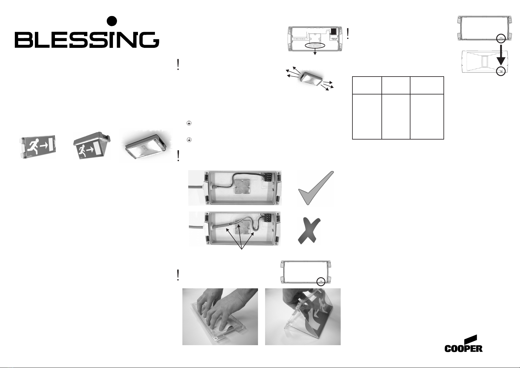
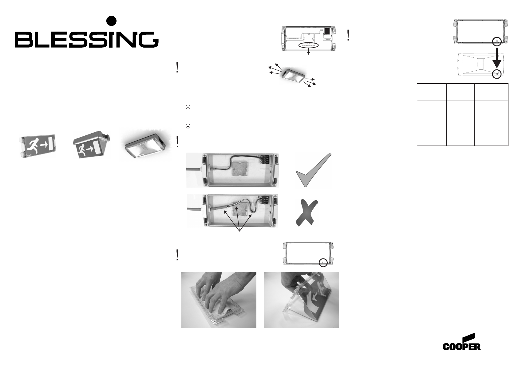
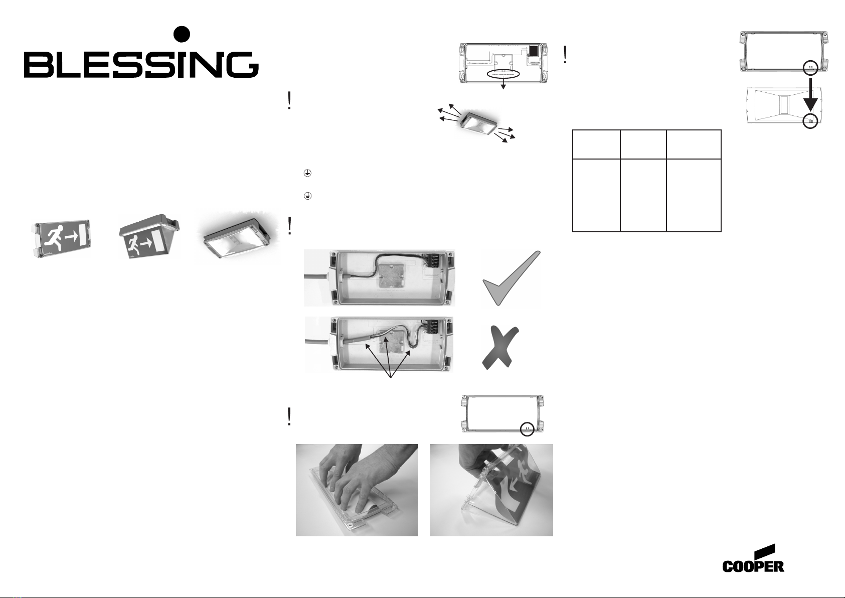
Bitte beachten Sie, dass sich der Hauptlicht-
austritt der Atlantic R im Gegensatz zu
konventionellen Leuchtstofflampen-
Leuchten an den kurzen Seiten befindet.
Schließen Sie die Leuchte nun an:
Atlantic LED Einzelbatterieversionen (AT):
N : Neutralleiter
L1 : ungeschaltete Phase
L2 : geschaltete Phase
: Schutzleiter (Erde)
Atlantic LED Zentralbatterieversion (230-CG):
N : Neutralleiter
L1 : Phase
: Schutzleiter (Erde)
Die Leitungen sind kurz hinter der Einführung abzumanteln. und so kurz
wie möglich zu halten . Sie dürfen nur innerhalb der gekennzeichneten
Bereiche verlegt werden. Die quadratische Fläche in der Leuchtenmitte
freihalten.
Atlantic LED S und D Varianten: Befestigen Sie ein (S) oder zwei (D)
Piktogramme in der Abdeckung.
Atlantic LED S: Beim Einsetzen des Pikto-
grammes auf oben und unten der Abdeckung
achten.
Bringen Sie die Piktogramme vorsichtig in die richtige Lage und
überprüfen Sie den richtigen Sitz an allen Befestigungspunkten.
Als nächstes kann der Reflektor in die
Abdeckung geschnappt werden.
Auf die richtige Positionierung des Reflektors
achten.
Atlantic LED Einzelbatterieleuchten (AT):
Verbinden Sie die Batterie mit der Leiterkarte
und notieren Sie das Datum der Inbetriebnahme
Atlantic LED Zentralbatterieleuchte (230-CG):
In Verbindung mit CEAG ZB-S Anlagen:
Stellen Sie die Leuchtenadresse 1-20 ein
(siehe Tabelle rechts):
Leuchtentest Einzelbatterieleuchten (Atlantic LED AT und AT-3):
Sobald die Netzspannung anliegt, überprüfen, ob die grüne LED
leuchtet. Der Zeitpunkt des wöchentlichen Tests wird durch den
Zeitpunkt der ersten Verbindung der Batterie mit der Leiterkarte
festgelegt. Genau eine Woche nach diesem Zeitpunkt wird der erste
wöchentliche Test (2 Minuten) durchgeführt. In der 13ten Woche wird
ein vollständiger Betriebsdauertest durchgeführt. Es wird daher
empfohlen, einen Zeitpunkt außerhalb der normalen Betriebszeiten zu
wählen. Soll der Zeitpunkt korrigiert werden, muss die Batterie für 5
Sekunden abgeklemmt werden.
Exakt nach 24 h nach dem Netzanschluss wird ein erster
Betriebsdauertest ausgeführt. Wenn erforderlich, findet anschließend
eine Starkladung der Batterie statt. Eine völlig entladene Batterie wird
innerhalb max. 16 h wieder aufgeladen sein. Sollte es innerhalb 24 h
vor einem geplanten Test zu einem Netzausfall kommen, wird der Test
verschoben. Alle nachfolgenden Tests werden nicht verschoben.
Nach Netzrückkehr verbleibt die Leuchte weiter 2 min im Notbetrieb
(nachlaufendes Notlicht). Ist die Leuchte vollständig aufgeladen und
betriebsbereit kann durch Bewegen mit einem Magneten (Zubehör) im
Bereich der LED Anzeige ein Funktionstest gestartet werden.
Erläuterung der LED Anzeige:
- grün an, gelb aus: Standby, Leuchte wird geladen
- grün aus, gelb blinkt schnell Lichtquelle defekt
- grün aus, gelb blinkt langsam Nenn-Betriebsdauer wurde nicht
erreicht oder Ladestörung
Vor dem Austausch einer defekten Lichtquelle sollte die Batterie
abgeklemmt werden. Die Batterie muss ausgetauscht werden, sobald
die Nennbetriebsdauer nicht erreicht wird.
Dabei wird die Leuchte wieder in den Ausgangszustand versetzt (siehe
Testzeitpunkt oben).
Die Batterie sollte nur von Fachpersonal gewechselt werden.
Atlantic LED
Safety
Atlantic LED S
Einseitige
Rettungszeichen-
leuchte
Dauerlicht
Atlantic LED R,
Atlantic LED O
Fluchtwegleuchte
Antipanikleuchte
Bereitschaftslicht
(schaltbar)
Atlantic LED D
Doppelseitige
Rettungszeichen-
leuchte
Dauerlicht
oben
unten
Cooper Safety BV
P.O. Box 3397
4800 DJ Breda
Netherlands
Tel. +31 (0)76 750 53 00
Fax +31 (0)76 587 14 22
www.coopersafety.nl
Adress-
schalter 1
(0,1,2)
0
0
0
....
1
....
2
Leuchten-
adresse
Überwachung
aus
01
02
....
11
....
20
Adress-
schalter 2
(0...9)
0
1
2
....
1
....
0
Als nächstes die
Abdeckung mit Reflektor
auf die Leuchte aufsetzen.
Dabei auf die richtige Lage
des Steckverbinders am
Reflektor in Verbindung mit
der Anschlussklemme
achten.
Ziehen Sie die 4 Schrauben
gleichmäßig und vorsichtig
an.
Bei Wandmontage
diese Seite unten
230 V, -10 %, +6 %, 50 Hz
200 lm
0...+25 °C
AC: 230 V, -10 %, +15 %, 50 Hz
(6 W, 7 VA)
DC: 180 - 254 V
200 lm
0...+30 °C
AC: 230 V, -10 %, +15 %, 50 Hz
(6 W, 7 VA)
DC: 176 - 275 V
22 mA @ 220 VDC
200 lm
-20...+40 °C
Einzelbatterieleuchten Atlantic LED AT und AT-3:
- Anschlussspannung
- Nennlichtstrom
- Zul. Umgebungstemperatur
Zentralbatterieleuchten Atlantic LED 230-HF:
- Anschlussspannung
- Nennlichtstrom
- Zul. Umgebungstemperatur
Zentralbatterieleuchten Atlantic LED 230-CG:
- Anschlussspannung
- Stromaufnahme Batteriebetrieb
- Nennlichtstrom
- Zul. Umgebungstemperatur
3/4
712.000.004
110316

Mounting and connection:
This luminaire is intended only for fixed mounting and permanent direct
connection to the mains supply.
Prepare the required cable entry and fit
a cable gland. Fix the gallery to the ceiling
or wall using the stainless steel screws.
(included)
Please note that Atlantic LED R escape
route lighting mainly emits light from the
short sides, contrary to conventional
fluorescent lighting.
Next make the electrical connections:
Atlantic LED self contained emergency lighting (AT):
N : neutral
L1 : unswitched live
L2 : switched live
: protective earth
Atlantic LED slave emergency lighting (230-CG):
N + L1: 230 V AC/DC
: protective earth
The cable jacket must be removed just behind the gland.
Because of the limited space, the wires must be kept as short as
possible and should only be placed within the indicated space. The
increased square area in the middle of the gallery must also be kept
free of wiring.
Atlantic LED S and D versions: Fix one (S) or two (D) pictograms in the
diffuser.
Atlantic LED S: When applying a pictogram
please note the difference between top and
bottom side of the diffuser.
Put the pictogram(s) carefully in place and verify if they are locked
behind the right edges.
Next, the diffuser and the reflector unit can
be snapped together.
Please note the diffuser fits only one way to
reflector unit.
Atlantic LED self contained emergency
lighting (AT):
Connect the battery cable to the circuit board.
Atlantic LED slave emergency lighting (230-CG):
Adjust the address switches on the ballast
module:
Testing Atlantic LED self contained emergency lighting (AT):
As soon as the mains voltage has been connected, check that the
green LED is on. Connecting the battery connector to the PCB during
installation defines the start time of the weekly tests. Exactly one week
after the battery is connected, the first weekly test takes place with a
duration of two minutes. In the thirteenth week a complete emergency
duration test will take place. It is recommended, if possible, to select the
test time at the beginning of a period in which the area is likely to be
unoccupied. This moment can be changed by disconnecting the battery
for 5 seconds. Exactly 24 hours after connection of the mains a first
duration test will be carried out. If neccessary the NiMH battery will be
fast charged. A completely discharged battery will be fully recharged
within a maximum of 16 hours. If a mains failure occurs during the 24
hours before a scheduled test, this test will be delayed. The test timing
for all subsequent tests remains unchanged.
When the luminaire is stand-by and
fully recharged, an additional function test of 2 minutes can be initiated
by moving the test magnet (accessory) along the LED indicator.
Explanation of the LED indication:
- green on, yellow off: stand-by
- green off, yellow blinking fast: light source defective
- green off, yellow blinking slow: emergency duration not sufficient or
charge current incorrect
Before replacement of a defective light source the battery should be
disconnected from the circuit board.
The battery should be replaced if the emergency duration is not
sufficient. By doing this the luminaire will be reset. Battery replacement
should be performed by a competent person.
In the event of a mains
failure, the luminaire will remain in emergency mode for an additional
two minutes after mains is restored.
230 V, -10 %, +6 %, 50 Hz
200 lm
0...+25 °C
AC: 230 V, -10 %, +15 %, 50 Hz
(6 W, 7 VA)
DC: 176 - 275 V
(22 mA @ 220 VDC)
200 lm
-20...+40 °C
AC: 230 V, -10 %, +15 %, 50 Hz
(6 W, 7 VA)
DC: 180 - 254 V
200 lm
0...+30 °C
Safety
Atlantic LED S
single sided
safety sign
maintained
(switchable)
Atlantic LED R,
Atlantic LED O
escape route lighting,
open area lighting
(non) maintained
(switchable)
Atlantic LED D
double sided
safety sign
maintained
(switchable)
Self contained emergency lighting Atlantic LED AT and AT-3:
- voltage
- rated lumen output
- ambient temperature
- voltage
Slave emergency lighting Atlantic LED 230-CG:
- voltage
- rated lumen output
- ambient temperature
Slave emergency lighting Atlantic LED 230-HF:
- rated lumen output
- ambient temperature
top
bottom
Cooper Safety BV
P.O. Box 3397
4800 DJ Breda
Netherlands
Tel. +31 (0)76 750 53 00
Fax +31 (0)76 587 14 22
www.coopersafety.nl
st
1 address-
switch
(0,1,2)
0
0
0
....
1
....
2
luminaire
address:
monitoring
off
01
02
....
11
....
20
nd
2 address-
switch
(0...9)
0
1
2
....
1
....
0
Next, the combined diffuser
and reflector unit can be
placed in the gallery.
Check beforehand whether
the position of the
connectors on the reflector
unit and the gallery
correspond and then insert
the unit in the gallery.
Tighten the 4 bolts carefully
and securely.
For wall fixing
this side down
4/4
712.000.004
110316
Atlantic LED
This manual suits for next models
4
Table of contents
Languages:
Other Cooper safety Lighting Equipment manuals