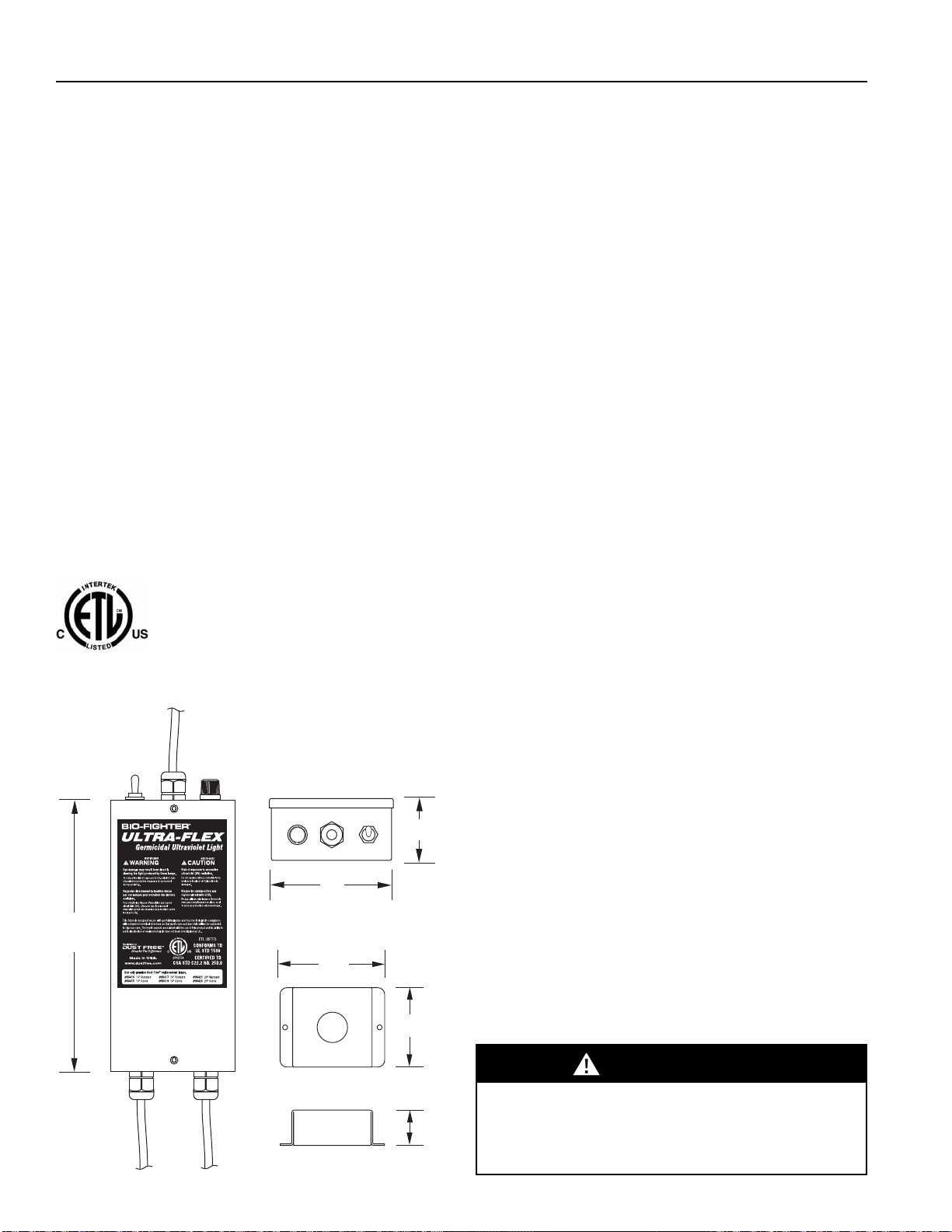
BIO-FIGHTER® ULTRA-FLEX INSTALLATION & OPERATION MANUAL
6
UV-C Light Hazard.
UV-C light can cause temporary or permanent loss of
vision, and sunburn. Take precautions to protect eyes
and skin from direct exposure.
WARNING
LAMP REPLACEMENT(Annually)
The lamp should be replaced annually even if
it appears to be operating normally. UV-C
energy production diminishes over time.
1. Obtain the correct replacement lamp for
your model.
2. Disconnect power to the equipment. Allow
lamp to cool 10 minutes before touching.
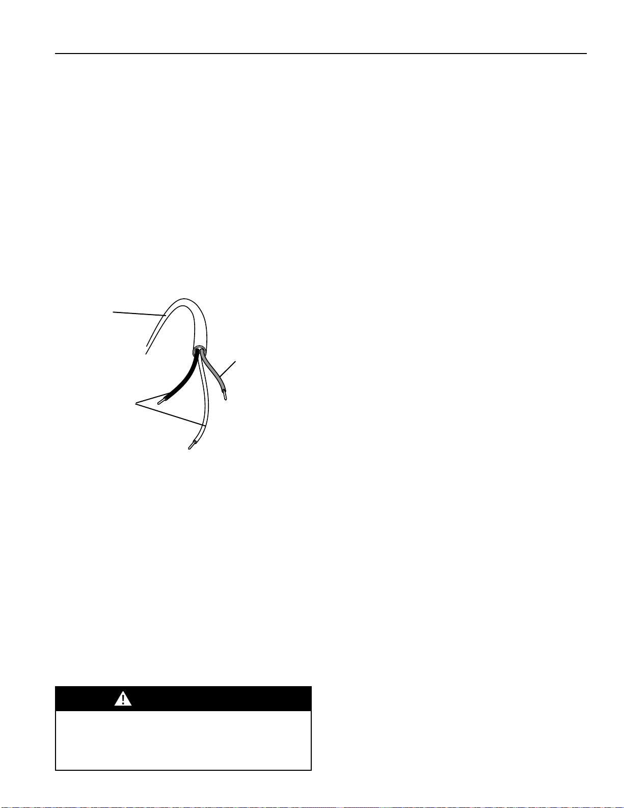
4. Disconnect the lamp harness.
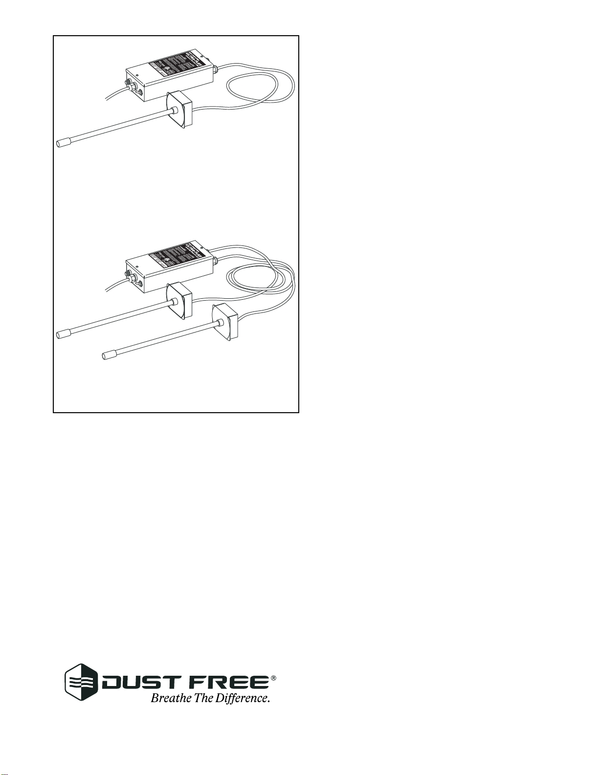
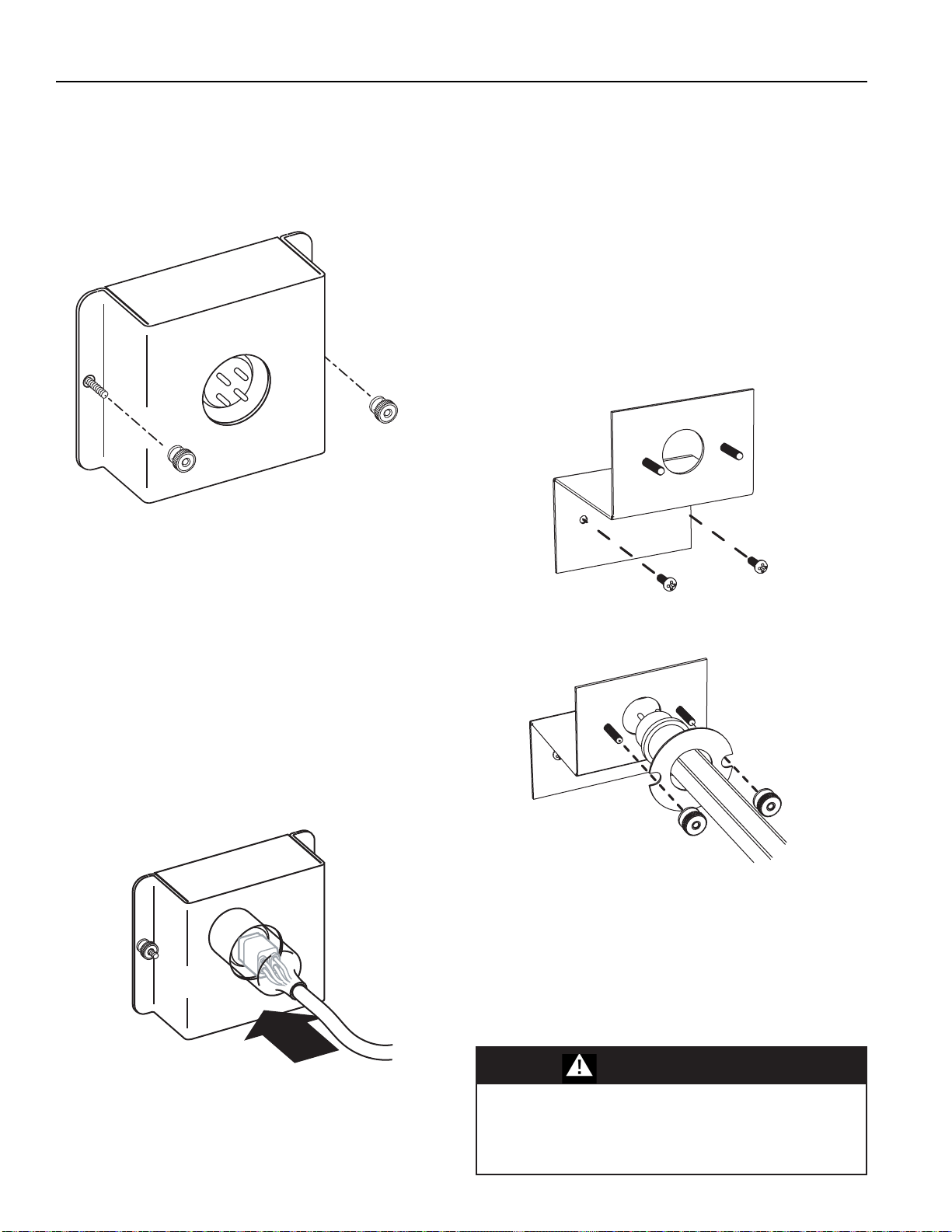
5. Remove the remote lamp housing. (Not
required for internal lamp mount option.)
6. Unscrew the two knurled nuts of the lamp
retaining bracket and slide the bracket
away from the lamp retaining lip. For inter-
nal lamp mount option, remove the two
knurled nuts and lamp retaining washer.
7. Carefully remove the UV-C lamp and
replace it with the new lamp. Be sure to
clean the lamp of dust and fingerprints
prior to installation.
8. Slide the retaining bracket back in place
and tighten knurled nuts. For internal lamp
mount option, secure the lamp with the
lamp retaining washer and fasten with
knurled nuts.
9. Reattach the remote lamp housing. The
remote lamp housing must be in place
prior to attaching the lamp harness. (Not
required for internal lamp mount option.)
10. Reconnect lamp harness.
11. Reconnect power.
12. Verify operation using viewport.
Burn Hazard.
During replacement, allow lamps to cool 10 minutes
before removing them. Personal injury may result.
WARNING
Mercury Hazard. Do Not Break.
Each UV-C lamp contains a small amount of Mercury.
May cause redness or irritation. Use proper disposal
techniques in case of breakage.
WARNING
LAMP DISPOSAL
Dispose of your spent UV-C lamps at your
local recycling center. You may also send your
spent lamps in the same container you
received your replacement lamps to:
Dust Free® Lamp Reclamation
1112 Industrial Drive
Royse City, TX 75189
PROPER CLEAN-UP TECHNIQUE IN CASE OF
LAMP BREAKAGE
GWear protective gloves, eyewear and mask.
GSweep the broken glass and debris into a plastic
bag, seal the bag, and dispose of properly.
Contact your local waste management office for
proper disposal.
GDo not use a vacuum cleaner. Do not
incinerate.
Replacement Parts Part No.
UVC Lamp - 14" 06413
UVC Lamp - 16" 06417
UVC Lamp - 20" 06421
UVC-O3 Lamp - 14" 06415
UVC-03 Lamp - 16" 06419
UVC-O3 Lamp - 20" 06423
Ballast - Multi-Voltage 06426
Power Cord - Whip-Type 06303
On/Off Switch 06617
Slide Bracket Springs (2) 210-0005-001
Slide Bracket 210929-00
Knurled Nuts (2) 210226-00
Fuseholder 212225-00
Fuse 750-0108-001
For information on the dealer in your area call: 1-972-635-9564.
Visit us at http://www.dustfree.com