Cooper Security 714r User manual

1
714r EN
NL
Fr
It
Dk
N
Sv
De
Es
Pt

2
Part No. 497358 Issue 1
This product complies with the requirements of European Directive: 1995/5/EC (Radio
&Telecommunications Terminal Equipment Directive).

3
2.4m
(max) 15m
Look down zone
Kruipzone
Zone basse
Melderzone nach unten
Zone Antistrisciamento
Zona de visión hacia abajo
Zona de vigilância
Se ned zone
Se ned sone
Fig. 1

4
Pet Alley mirror raised
Spiegel kruipzone omhoog
Lentille orientée vers le haut
Angehobener Haustiergassenspiegel
Copertura sollevata
Espejo del callejón de mascotas elevado
Espelho da passagem de animais de estimação levantado
Husdyrspejlet slået op
Husdjurspassage spegel hävd
Husdyrspeil slått opp
Pet Alley mirror lowered
Spiegel kruipzone omlaag
Lentille orientée vers le bas
Gesenkter Haustiergassenspiegel
Copertura abbassata
Espejo del callejón de mascotas bajado
Espelho da passagem de animais de estimação descido
Husdyrspejlet slået ned
Husdjurspassage spegel sänkt
Husdyrspeil slått ned
Fig. 2

5
Vertical corner mount
Hoekmontage
Montage en angle droit
Flache Wandmontage
Montaje plano en pared
Montagem em canto vertical
Lodret hjønemontering
Vertikal vägghörn montage
Loddrett hjørnemontering
Flat wall mount
Vlakkewandmontage
Montage en saillie
Vertikale Eckmontage
Montaje vertical en esquina
Montering fladt på væggen
Platt väggmontage
Montering flatt på veggen
Fig. 3

6
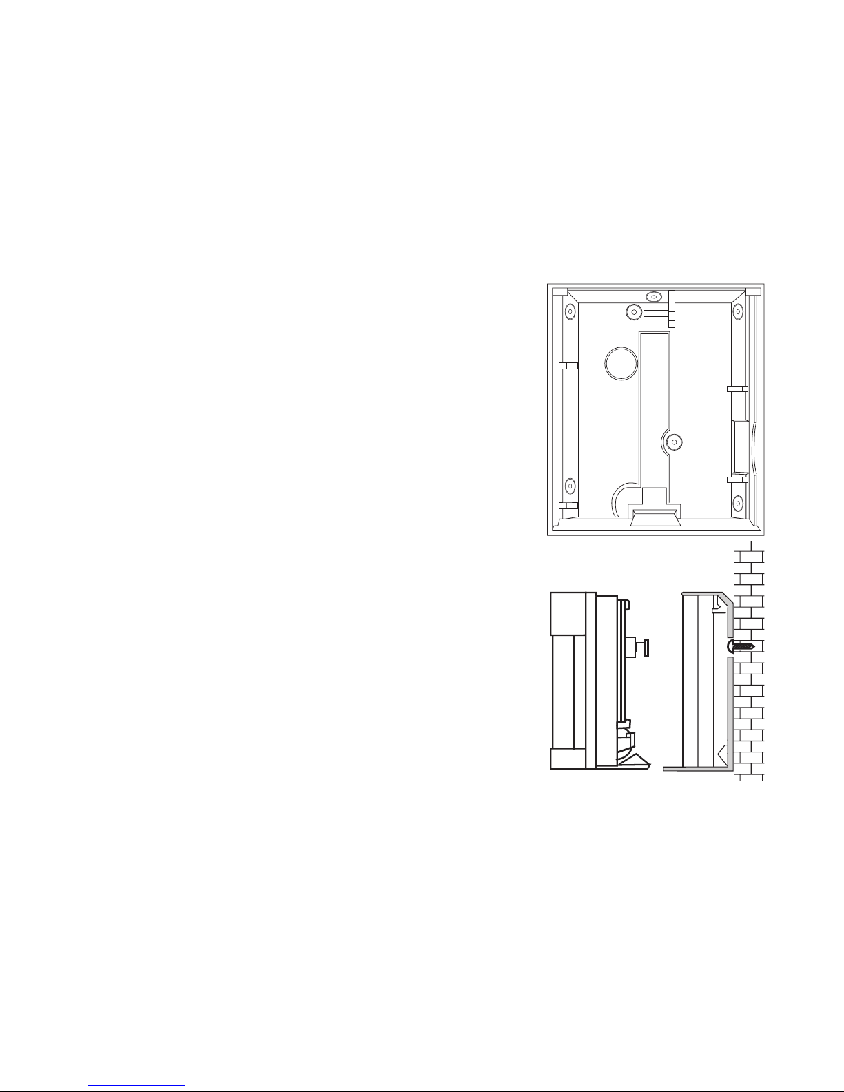
Wall tamper knock out
Gat tbv wandsabotage
Prédécoupe destinée à un contact d’autoprotection à l’arrachement
Entfernbares Stanzteil für Wand-manipulationsschutz
Foro per Tamper a Parete
Pieza desprendible de interruptor de pared.
Montagem direita na parede
Udstansning til montering af sabotageovervågning på vægen
Våggsabotage utslag
Utstansing for montering av sabotasjeovervåking på veggen
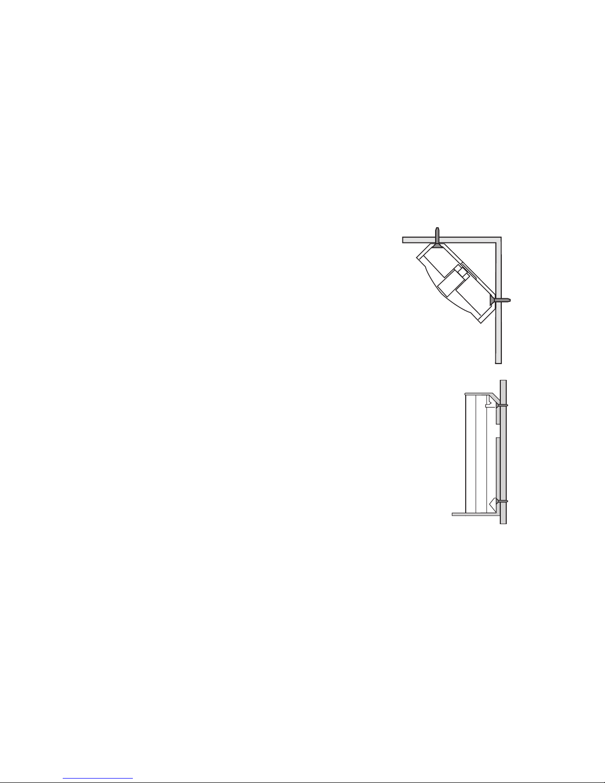
M3 (No4) screw no more than 2.5 mm proud from wall
M3 (No4) schroef niet meer dan 2,5mm uit de muur
Vis M3 (N° 4) ne devant pas dépasser de plus de 2,5 mm du mur
M3-Schraube (Nr. 4); darf nicht mehr als 2,5 mm aus Wand ragen
Vite M3 (No4) non sporgente più di 2.5 mm dalla parete
Tornillo M3 No. 4), sin sobresalir más de 2,5 mm. de la pared.
M3 (Nr. 4) skrue ikke mere end 2,5 mm fra væggenl
M3 (Nr 4) skriva ej längre ur väggen än 2,5 mm
M3 (nr 4) skrue ikke mer enn 2.5 mm fra veggen
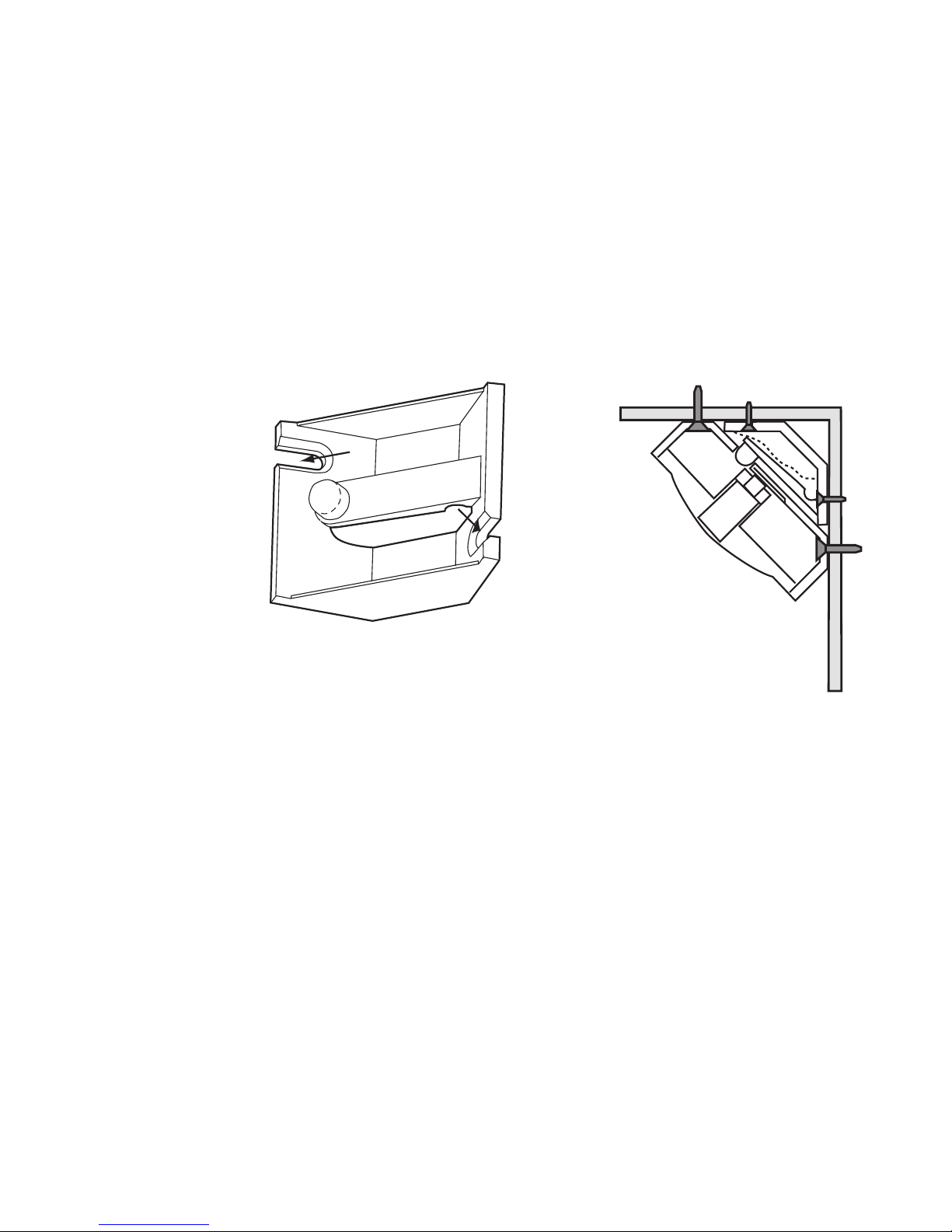
Fig. 4

7
Fig. 5

8

9
EN
Introduction
The 714r Passive Infra Red (PIR) is an indoor detector designed to work with Scantronic
868MHz receivers. The PIR detects movement of body heat. The detector has a fan
shaped sensitive area approximately 15 metres in radius. The case is protected by an in-
ternal tamper switch. The back of the case can be modified by removing a cutout to provide
a wall tamper.
Specification
Part No. 714rEUR-00
Power Supply 1 x AA 3.6V Lithium cell
Battery Life Approximately 14 months
Operating temp: -10 to +55 °C
Environmental Class I (tested -10 to +55°C)
Low voltage alarm: 2.4V nominal
Lens: Standard 15m x 90 deg.
White light filter: greater than 2000 Lux
RF Immunity: 10V/m
Dimensions: 82mm x 71mm x 47mm x (HxWxD)
Operating Frequency: 868,6625 MHz
Security Grade II
INCERT C0160202
Specification subject to change without notice.

10
Siting
You can mount the unit either flat against the wall, or in a corner. The area covered by the
detector is shown in Figure 1.
DO mount the unit between 1.8 and 2.4 metres high for the best general coverage in an
average room.
Do NOT mount the unit:
Facing a fire, boiler or window.
Over a radiator.
Near the floor.
Close to or on large metal structures.
Closer than one metre to mains wiring and metal water or gas pipes.
Inside steel enclosures.
Next to electronic equipment, particularly computers, photocopiers or other radio
equipment.
Closer than 30mm to a ceiling (to allow space for dismounting the unit in the future).
Installation
Open the detector by lifting the flap at the top of the case and removing the screw con-
cealed underneath.
Install one ‘AA’ size 3.6V lithium battery (supplied).
Note: If the transmitter shows a continuously pulsing glow from the activity LED then a fault
has occurred or the battery is totally exhausted. Replace the battery and check that the
activity LED is working normally.

11
EN
Pet Alley
1. Remove the PCB from the sensor funnel.
2. Swing down the pet alley mirror (see Figure 2). This deletes all but the top row of the
detector zones.
Note: When using the pet alley mirror mount the detector at 1.6m height in order to main-
tain correct coverage with the upper detector zones. Pet immunity extends for 10m. Do not
use this facility in larger areas.
3. Refit the pcb to the sensor funnel .
Mount the back
The 714r is designed for mounting by any of the methods shown in Figure 3. The case
back contains a number of possible fixing holes, marked by mouldings in the plastic. Chose
two to suit the location you have selected, and drill them out carefull.
1. Hold the back in location and mark and drill 5mm fixing holes in the wall.
2. Secure the back to the wall with 16mm countersunk head screws and wall plugs.
3. Clip the body of the detector to the back.
Fitting a Wall Tamper
If you wish to fit a wall tamper:
1. Cut out the large circle indicated in the back of the case (see Figure 4).
Make sure that you remove enough material so that the head of the tamper switch can
pass freely through the back of the case.
2. Mark the position of this circle on the wall at the place where the case back will be fit-
ted.

12
3. Drill and plug a hole in the wall at the marked position, and insert a M3 (No 4) screw.
Make sure the head of the screw is no more than 2.5 mm from the wall.
Caution: Do not allow the head of the screw to protrude more than 2.5mm from the
wall or you may damage the PIR.
4. Mount the case back so that the head of the screw protrudes through the cut out and
engages the tamper switch when the body of the detector is fitted (see Figure belo).
You may have to adjust the height of the screw until it operates the tamper switch. The
body of the PIR should fit easily into the case back without force.
Fitting a Corner Wall Tamper
If you want to fit the 714r in a corner and also fit a wall tamper then you should use the
Scantronic Corner Wall Tamper Bracket (Part No. 235385), see Figure 5.
To fit a wall tamper in a corner mounting:
1. Fit the bracket into the corner. Make sure that it is the correct way up. The stud on the
end of the arm should be at the left.
2. Cut out the large circle indicated in the back of the PIR case. Make sure that you
remove enough material so that the stud of the Wall Tamper Bracket can pass freely
through the back of the case.
3. Fit the PIR case back into the corner on top of the Corner Wall Tamper Bracket. Make
sure the stud on the bracket passes through the hole in the back of the PIR case (see
Figure 5).
4. Fit the body of the PIR to the case back. The body of the PIR should fit easily into the
case back without force.

13
EN
Learning
Consult the relevant section in the receiver’s Installation and Programming Guide.
Testing.
1. Put the control unit into walk test.
2. Hold the detector in place.
3. Trigger the detector.
4. Make sure the panel receives the alarm.
5. Chose another site for the detector if the panel does not receive the signal.
6. Stop the walk test at the control unit.
PIR Testing and Lockout
In normal use the 714r uses a lockout timer in order to extend battery life. The lockout timer
works like this:
a) The unit detects movement, signals the panel, and starts the lockout timer.
b) When the lockout timer expires the unit signals the panel the next time it detects move-
ment.
Cooper Security Ltd set the lockout timer to three minutes when the 714r leaves the fac-
tory. If you wish to change the lockout timer to one minute then remove the jumper link
on the back of the PCB. (Replace the link to restore the lockout timer to three minutes.)
Cooper Security Ltd recommends that you leave the jumper fitted. Removing the jumper
for long periods will reduce the life of the battery.
If you want to test a 714r in normal use you should leave the protected area and wait at
least four minutes between activations (two minutes if you have removed the link). To make

14
testing easier the detector changes the lockout period to 10 seconds for the first half hour
after you put the battery in, or after you trigger its tamper.
Note: Make sure the control unit is in programming mode before you open or move any
of the detectors. This will avoid setting the tamper alarm off.
When you have fitted and adjusted the 714r test the operation of the complete detector as
follows:
1. Put the control unit into walk test.
2. Clear the protected area and make four random direction walk tests. Using an adult hu-
man, walk at a rate of one normal step per second within the detection pattern. The unit
should alarm within three out of the four walk tests.
3. Stand outside the protected pattern and operate any potential cause of false alarm,
e.g., operate lights, open doors, etc. If the unit detects the deliberate cause of false
alarm, try readjusting the detector pattern.
4. Stand outside the detection pattern and observe the detector operation for three to five
minutes without doing anything. The detector should not alarm. If the detector does
alarm, locate the cause and correct it.
Note: When walk testing, cross the sensitive zones at right angles in an upright position.
The LED remains off if the battery has been in for longer than 30 minutes, or if you have
not triggered the detector tamper within the last 30 minutes.

15
EN
Maintenance
Inspect the 714r one or more times a year. The inspection should consist of , but be not
limited to, the mounting, the battery, cleaning dust from the lens with a soft cloth, walk test-
ing and unit operation.
Service
If the transmitter shows a continuously pulsing glow from the activity LED then a fault has
occurred or the battery is totally exhausted. Replace the battery and check that the activity
LED is working normally.
If the activity LED still gives a pulsing glow after inserting a good battery then the unit has
a fault. Return the unit to your supplier.

16
© Cooper Security Limited 2005
Every effort has been made to ensure that the contents of this leaflet are correct . How-
ever, neither the authors nor Cooper Security Limited accept any liability for loss or dam-
age caused or alleged to be caused directly or indirectly by this leaflet. The contents of this
leaflet are subject to change without notice.
Printed and published in the U.K.

17
NL
Introductie
De draadloze passief infrarood (PIR) detector 714r voor binnenshuis, is ontwikkeld voor
toepassing met 868 MHz ontvangers van Scantronic. De PIR detecteert bewegingen van
lichaamswarmte. De detector heeft een waaiervormig detectiegebied met een radius van
circa 15 meter. De behuizing wordt beveiligd door een sabotageschakelaar. Aan de achter-
kant kan nog een muursabotageschakelaar worden aangebracht.
Specificaties
Artikelnr.: 714rEUR-00
Voeding: Lithium batterij; AA; 3,6VDC
Temperatuurbereik: -10 tot +55 °C
Batterij-laag melding: 2,4V nominaal
Lens: Standaard 15m x 90 graden
Wit licht fileter: meer dan 2.000 Lux
RF Immuniteit: 10V/m
Afmetingen: 82mm x 71mm x 47mm x (HxBxD)
Frequentie: 868,6625 MHz
Milieuklasse I (Getest op -10 tot +55 °C)
Beveiligingsklasse II
INCERT C0160202

18
Projectie
U kunt de detector zowel vlak op een muur als in een hoek plaatsen. Hieronder ziet u het
bereik.
Voor het beste resultaat in een gemiddelde ruimte plaatst u de detector op een hoogte van
1,8 tot 2,4 meter.
Plaats de detector NIET:
Gericht op een vuurhaard, boiler, geiser, cv-installatie of raam;
Boven een radiator;
Vlak boven de grond;
Vlak bij grote metalen constructies;
Binnen 1 meter van elektrische leidingen en metalen water- en gasleidingen;
In een stalen omhulsel of kooiconstructie;
Vlak bij elektronische apparatuur zoals computers, faxen en kopieerapparaten;
Minder dan 30 cm van het plafond (U heeft die ruimte minimaal nodig voor
(de)montage).
Installatie
Til de klep aan de bovenkant van de behuizing op en draai de schroef daaronder los. Open
de detector.
Plaats de bijgeleverde Lithium batterij (AA 3,6VDC).
Opm.: Als de LED van de detector regelmatig pulseert wijst dit op een elektronisch manke-
ment of de batterij levert onvoldoende spanning. Vervang de batterij en controleer de LED.

19
NL
Kruipzone
1. Neem de PCB uit de houder.
2. Klap de spiegel voor de kruipzone naar beneden. Hierdoor blokkeert u alle detecti-
ezones behalve de bovenste rij.
Opm.: Als u de kruipzone gebruikt plaatst u de detector op een hoogte van 1,6 meter. Zo
houdt u een juist bereik van de bovenste detectiezones. In deze positie heeft de detector
een bereik van 10 meter. Gebruik deze mogelijkheid niet in grote ruimtes.
3. Plaats de PCB terug in de houder.
Wandmontage
De 714r kan op elk van de onderstaande manieren worden gemonteerd. De achterkant
van de behuizing bevat een aantal voorbewerkte montagegaten. Kies hiervan twee gaten
voor uw lokatie en boor ze voorzichtig uit.
1. Houdt de wandplaat op de gewenste plaats. Markeer en boor 5mm gaten in de muur.
2. Monteer de wandplaat tegen de muur met pluggen en 16mm schroeven.
3. Klik de behuizing van de detector op de wandplaat.
Wandsabotage
Als u een wandsabotageschakelaar wilt aanbrengen:
1. Snij de grote cirkel uit de achterkant van de behuizing (zie hieronder).
Let op dat u voldoende materiaal wegsnijdt, zodat de kop van de sabotageschakelaar
en vrij doorheen kan.
2. Markeer de plaats van de cirkel op de muur.

20
3. Boor een gat op de aangegeven plaats en schroef een M3 (nr.4) schroef in een plug.
Let op dat de schroef niet meer dan 2,5mm uit de muur steekt.
Waarschuwing: Als de schroef meer dan 2,5 mm uit de muur steekt beschadigt de
detector.
4. Monteer de behuizing zodanig dat de kop van de schroef door het gat steekt en de
sabotageschakelaar raakt als de behuizing van de detector op de wandplaat is vastgek-
likt (zie hieronder).
Stel zonodig de afstand van de schroefkop op de juiste lengte in. De detector moet zonder
extra kracht op de wandplaat geklikt kunnen worden.
Hoeksabotage
Als u de 714r in een hoek wilt plaatsen en bovendien een wandsabotageschakelaar wilt
aanbrengen dient u montagebeugel 235385 van Scantronic te gebruiken (zie hieronder).
Als u een wandsabotageschakelaar in de hoek wilt plaatsten:
1. Monteer de montagebeugel in de hoek. Let er op dat de goede kant boven is. De
aanslag op het eind van de arm moet rechts zijn.
2. Snij de grote cirkel uit de achterkant van de behuizing. Let op dat u voldoende materiaal
wegsnijdt, zodat de kop van de sabotageschakelaar en vrij doorheen kan.
3. Monteer de wandplaat van de PIR op de montagebeugel. Controleer of de aanslag van
de montagebeugel door het gat van de wandplaat gaat (zie hierboven).
4. Plaats de PIR op de wandplaat. De detector moet zonder extra kracht op de wandplaat
geklikt kunnen worden.
Table of contents
Languages:
Other Cooper Security Accessories manuals
Popular Accessories manuals by other brands

MG International
MG International SENSOR SOLAR Use and installation manual

STEINEL
STEINEL STUDIOLINE IS 2180-5 operating instructions

Wenglor
Wenglor OCP801P0150P operating instructions

General Monitors
General Monitors 610 Calibration information

Philio
Philio PAT15 quick start guide

Sport-thieme
Sport-thieme 115 9501 Assembly instructions

Ontech
Ontech Relay 9015 quick start guide

IDEAL
IDEAL Audacy VSC1303 product manual

Batco
Batco 1565 SA Operator's manual

JANE
JANE KIDS ZONE 80273 manual

Safety Technology International
Safety Technology International STI-WS103 Installation and operating instructions

Parkside
Parkside PBKZ 1 A1 operating instructions