Safety
10
2
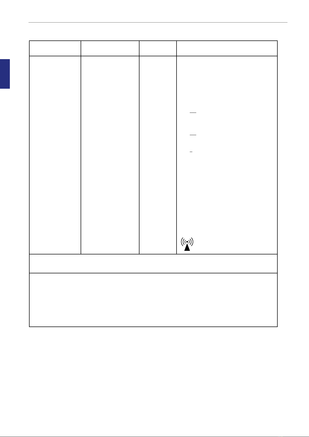
IMMUNITY Test IEC 61326-1
Test level
Compliance
level
Electromagnetic environment -
guidance
Conducted RF
IEC 61000-4-6
Radiated RF
IEC 61000-4-3
Not applicable
3 V/m
80 MHz to 1000 MHz
3V/m
1400 MHz to 2000 MHz
1V/m
2000 MHz to 2700 MHz
Not applicable
3 V/m
3V/m
1V/m
Portable and mobile RF communications
equipment should be used no closer to any
part of the G210, including cables, than the
recommended separation distance calculated
from the equation applicable to the frequency
of the transmitter
Recommended separation distance
d = [ 3,5 ] √P
3
d = [ 3,5 ] √P 80 MHz to 800 MHz
3
d = [ 7 ] √P 800 MHz to 2,5 GHz
3
Where P is the maximum output power rating
of the transmitter in watts (W) according to
the transmitter manufacturer and d is the
recommended separation distance in metres
(m).
Field strengths from fixed RF transmitters,
as determined by an electromagnetic site
survey,a should be less than the compliance
level in each frequency range. b
Interference may occur in the vicinity of
equipment marked with the following symbol:
NOTE 1 At 80 MHz and 800 MHz, the higher frequency range applies.
NOTE 2 These guidelines may not apply in all situations. Electromagnetic propagation is affected by absorption
and reflection from structures, objects and people.
a Field strengths from fixed transmitters, such as base stations for radio (cellular/cordless) telephones and land
mobile radios, amateur radio, AM and FM radio broadcast and TV broadcast cannot be predicted theoretically
with accuracy. To assess the electromagnetic environment due to fixed RF transmitters, an electromagnetic site
survey should be considered. If the measured field strength in the location in which the G210 is used exceeds
the applicable RF compliance level above, the G210 should be observed to verify normal operation. If abnormal
performance is observed, additional measures may be necessary, such as re-orienting or relocating the [System
Name here].
b Over the frequency range 150 kHz to 80 MHz, field strengths should be less than 3 V/m.