Cooper UTY User manual

UTY
BIKE
QUICK
START
GUIDE
UTY
BIKE
KURZ –
ANLEITUNG
// for more detailed instructions please refer to your UTY Bike manual
// detaillierte Anweisungen finden Sie in Ihrer UTY Bike-Bedienungsanleitung
www.cooperbikes.com

Inhalt / Contents
>> ENG
What‘s in the box
Assembly
Geometry
1.
2.
3.
01
02 – 03
04
//
//
//
>> DE
1.
2.
3.
01
02 – 03
04
//
//
//
Lieferumfang
Montage
Geometrie
Herzlichen Glückwunsch, du bist nun
stolze*r Besitzer*in eines UTY E-Bikes.
Anstatt eine lange Anleitung zu lesen,
willst du bestimmt direkt losradeln und
die Straßen erobern.
Um schnell und vor allem sicher in Fahrt
zu kommen, haben wir die wichtigsten
Aufbauinformationen
kompakt zusammengefasst.
Auf die Plätze, fertig, los!
Congratulations, now you are the proud
owner of a UTY pedelec. Instead of rea-
ding a long manual, you definitely want to
go riding and conquer the streets.
To get you going as quickly and safely
as possible we have compiled the most
important assembling information here.
On your marks, get set, go!
>> DE >> ENG
2 3
UTY QUICK START GUIDE UTY QUICK START GUIDE

1. Lieferumfang 1. What‘s in the box
MONTAGEMATERIAL TOOLS
SONSTIGES OTHER
E-BIKE E-BIKE
ZUBEHÖR ACCESORIES
– Montagefett 2g
– Maulschlüssel
8+10 mm | 15 mm
– Grease 2g
– Spanner
8+10 mm | 15 mm
– Bedienungsanleitung
– E-Bike, teilweise demontiert
– Vorderrad mit Schraubbefestigung
– 1 Set Pedale (li + re)
– Schutzblech
– E-bike, partially dismantled
– Front wheel with fastening screws
– Set of pedals (l + r)
– Front-mudguard
– Akkuladegerät
– Quick Start Guide
– Charger
– Quick Start Guide
– Inbusschlüssel
4 mm | 5 mm
– Hex key
4 mm | 5 mm
– Manual
optional
>> DE
>> DE
>> ENG
>> ENG
TOOLS
Überprüfe die Vollständigkeit deines UTY
Bikes anhand der Abbildung:
Check the completeness of your UTY-Bike
based on the illustration:
4 5
UTY QUICK START GUIDEUTY QUICK START GUIDE

2. Montage
1. AUSPACKEN UND AUFSTELLEN
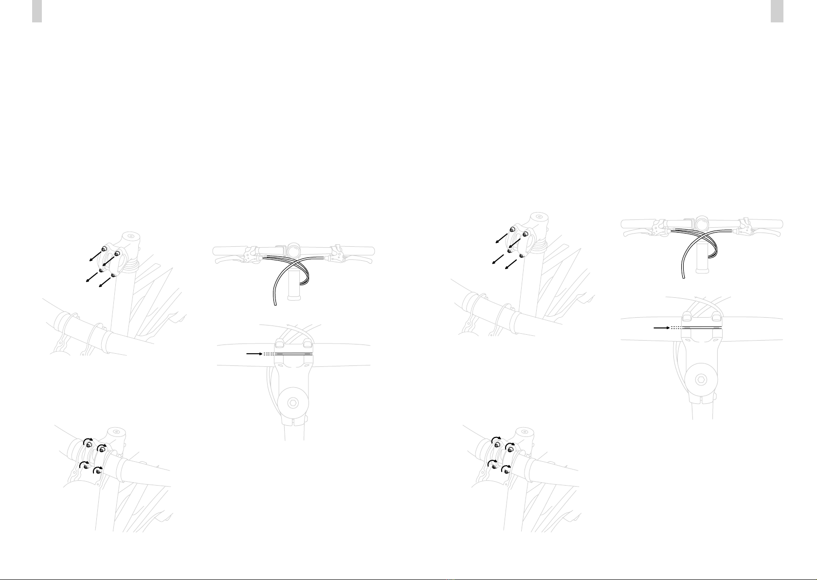
2. LENKER MONTIEREN
2. INSTALL HANDLEBARS
1. UNBOX AND SET UP
Montageunterlage bereitlegen (Karton oder
Stounterlage), Karton önen, Schutzkarto-
nage entnehmen und demontiertes Vorder-
rad vorsichtig herausnehmen. E-Bike aus
dem Karton entnehmen und mit der Gabel
auf der Montageunterlage stehend abstellen.
Transportschutz von Vorderrad und Gabel
entfernen.
Set up an assembly base (cardboard or fabric
base). Open the box and remove packaging,
take out the front wheel then remove the
e-bike from the box and rest it in an upright
position with the fork on the assembly base.
Entferne die 4 Schrauben der Lenkerklem-
mung am bereits vormontierten Vorbau.
Remove the 4 bolts from the handlebar clamp
on the pre-assembled stem.
Montiere den Lenker am Vorbau. Achte auf
eine mittige Position, eine korrekte Kabel-
führung* und eine ergonomisch angenehme
Positionierung der Bremsgrie, durch Drehen
des Lenkers im Vorbau.
Mount the fully pre-assembled handlebars on
the stem. Ensure a central position, correct ca-
ble routing* and an ergonomically comfortable
positioning of the brake levers by turning the
handlebars inside the stem.
Beachte eine kreuzweise Vorgehensweise
beim Anziehen der 4 Befestigungsschrauben
am Vorbau auf 5 Nm pro Schraube. Das
Spaltmaß zwischen Schelle und Vorbau läuft
nach dem korrekten Anziehen der Schrauben
parallel und ist auf der Ober- und Unterseite
gleich groß.
Kabel dürfen nicht verdreht sein und müssen
dem Bild entsprechend verlaufen. Der rechte
Bremshebel bedient die Hinterradbremse, der
linke Hebel die Vorderradbremse, im Vereinigten
Königreich Großbritannien und Nordirland ist dies
umgekehrt.
Crosswise tightening the 4 bolts on the stem
to 5 Nm per bolt. The gap between clamp
and stem runs parallel after correct tightening
of the bolts and is the same on the upper and
lower side.
Cables must not be twisted and routed according
to the picture. Right brake lever operates the rear
brake and the lef the front brake, in the United
Kingdom this is reversed.
*
*
2. Assembly
>> DE
>> DE ENG <<
>> ENG
Schalt- und Bremsseil korrekt verlegt
Shift and brake cable correctly routed
Spaltmaß gut
accurate Gap size and running parallel
3. VORDERRAD MONTIEREN 3. INSTALL FRONT WHEEL
Transportsicherung aus dem Bremssattel ent-
fernen. Vorderrad in die Gabel einsetzen. Den
Schnellspannverschluss handfest anziehen und
Spanner mit der geschlossenen Seite in Fahrt-
richtung zeigend nach hinten klappen. Der
Spanner „zieht“ ca. ab der Hälfte des Radius.
Remove the transport lock from the brake
calliper. Insert the front wheel into the fork.
Tighten the quick-release fastener hand-tight
then fold backward to fix the front wheel in
place. Light pressure should be used when
locking.
6 7
UTY QUICK START GUIDEUTY QUICK START GUIDE

4. SCHUTZBLECH MONTIEREN 4. INSTALL MUDGUARD
Mit der vormontierten Schraube, den Winkel
des Schutzblechs hinter dem Gabelkopf be-
festigen. Mit dem 5 mm Inbusschlüssel und
10 mm Maulschlüssel anziehen.
Using the pre-mounted bolt, fasten the angle
of the mudguard behind the fork crown.
Tighten with the 5 mm Allen key and
10 mm spanner.
Zur einfacheren Weiterbearbeitung kann nun
das Bike auf den vormontierten Seitenständer
gestellt werden.
To make further assembly easier, the bike can
now be placed on the pre-fitted bike stand.
ACHTUNG:
Die Vorderrad-Achse muss dabei vollständig in
der Gabel sitzen. (Die Beläge der vormontierten
Vorderrad-Bremse laufen schleirei an der Brems-
scheibe vorbei)
CAUTION:
The front wheel axle must be fully inserted in the
fork. (The pads of the pre-mounted front wheel
brake run past the brake disc without dragging).
Dann die Schutzblechstreben an den seitlichen
Gewindeösen der Gabel montieren und mit
einem 3 mm Inbusschlüssel festziehen.
Then mount the mudguard stays on the side
eyelets of the fork and tighten with a 3mm
Allan key.
TIPP:
Der Schnellspanner muss gegebenenfalls wieder
gelöst werden um das Schutzblech festschrauben
zu können.
TIP:
Perhaps you have to open the quick-release
before you mount the mudguard.
5. SATTEL MONTIEREN 5. INSTALL SADDLE
Sattelstütze im Einschubbereich leicht ein-
fetten und in das Sitzrohr einführen, auf die
gewünschte Sattelhöhe schieben, gerade
ausrichten und an der Klemmschelle fixieren.
Hierzu den beiliegenden 4 mm Inbusschlüssel
verwenden. Die an der Sattelstütze gekenn-
zeichnete Mindesttiefe des Einschubs ist un-
bedingt zu beachten!
Grease the seatpost before inserting into the
seat tube, slide it to the desired saddle height,
align it straight and fix in place by tightening
the clamp with the 4 mm Allen key. When
adjusting the saddle height, do not exceed the
maximum saddle height mark on the saddle
tube.
>> DE ENG <<
8 9
UTY QUICK START GUIDEUTY QUICK START GUIDE

HINWEIS:
Das rechte und linke Pedal unterscheiden sich
und dürfen nicht vertauscht werden. Das linke
Pedal ist mit Riefen gekennzeichnet (siehe
Abbildung:
NOTICE:
The right and left pedals are dierent and should
not be interchanged. The left pedal is marked
with grooves (see figure):
TIPP:
Der Sattel sollte so eingestellt sein, dass du bei
fast ausgestrecktem Bein das Pedal mit der Ferse
erreichst.
TIP:
The saddle should be adjusted so that you can
reach the pedal with your heel when your leg is
almost fully extended.
7. GEPÄCKTRÄGER MONTIEREN
(wenn als Zubehör gekauft)
7. INSTALL FRONTCARRIER
(If purchased as an accessory)
Zur Gepäckträger Montage werden die 4 be-
reits vormontierten Schrauben am Steuerrohr
demontiert.
For carrier assembly remove the 4 already
pre-installed bolts with a 4 mm allen key.
6. PEDALE MONTIEREN 6. INSTALL PEDALS
Das Pedalgewinde zuerst leicht einfetten.
Schraube zunächst das rechte Pedal auf der
rechten Fahrradseite in Fahrtrichtung handfest
an. Nutze zum abschließenden Festziehen den
15er Maulschlüssel und ziehe die Pedale mit
ca. 30 Nm fest. Wiederhole den Vorgang mit
dem linken Pedal - drehe diesmal gegen den
Uhrzeigersinn.
First grease the thread of the pedals, then
attach your pedal, screw each pedal onto its
corresponding thread with your hands at first
(from a riders persepective, turning clockwise
for the right pedal and counterclockwise for
the left). For final tightening, please repeat the
process using the 15 mm spanner and tighten
the pedals to approx. 30 Nm.
links leftrechts right
Anschließend die Bohrungen des Frontloaders
mit den Bohrungen am Steuerrohr ausrichten
und wieder mit dem 4 mm Inbusschlüssel
festziehen.
Then align the holes of the front loader with
those on the head tube and fasten again with
the 4 mm bolts.
>> DE ENG <<
10 11
UTY QUICK START GUIDEUTY QUICK START GUIDE

3. Abmessungen
WEITERE INFORMATIONEN
Bitte beachten: die technischen Daten des
E-Bikes können sich ändern.
Declarations in mmAngaben in mm
MORE INFORMATION
Please note: bike specification may be subject
to change.
3. Geometry
A– Radstand 1025,3
B– Sitzrohr 450
C– Sitzrohrwinkel 70°
D– Oberrohr hor. 590
E– Reach 370,3
F– Lenkwinkel 70°
G– Steuerrohr 330
H– Stack 603,7
I– Durchstiegshöhe 654,9
J– Tretlagerabsenkung +20
K– Gabel Vorlauf 20
L– Kettenstrebe eektiv 406,7
A– Wheelbase 1025.3
B– Seat tube 450
C– Seat tube angle 70°
D– Top tube hor. 590
E– Reach 370.3
F– Head tube angle 70°
G– Head tube 330
H– Stack 603.7
I– Standover height 654.9
J– BB drop +20
K– Fork oset 20
L– Chainstay eective 406.7
LOS GEHT´S! HAVE FUN!
Jetzt sind du und dein UTY E-Bike bereit die
Welt zu erkunden. Wir wünschen dir viele
tolle Fahrten mit deinem Bike und freuen uns
immer sehr darüber, wenn du deine Erlebnisse
mit uns teilst.
Vergiss deshalb nicht uns zu folgen:
Now you and your UTY e-bike are ready to
explore the world. We wish you many great
rides with your bike and are happy when you
share your experiences with us.
So don‘t forget to follow us:
>> DE ENG <<
A A
C C
G G
H H
I I
J J
K K
L L
F F
D D
E E
B B
ACHTUNG:
Akku vor der ersten Fahrt laden!
CAUTION:
Charge the battery before the first ride!
12 13
UTY QUICK START GUIDEUTY QUICK START GUIDE


Die TechniBike GmbH ist exklusiver Rechteinhaber für Entwicklung, Herstellung und weltweiten
Vertrieb von UTY by Cooper Bikes. Anteile der TechniBike GmbH gehören der LEPPER Stiftung.
www.uty.com
Other Cooper Bicycle manuals