LFB CT26-15 User manual

USER MANUAL
CT26-15
THIS MANUAL CONTAINS IMPORTANT INSTRUCTIONS FOR SAFETY AND
OPERATION.
At the end of this manual:
YOUR WARRANTY CERTIFICATE
«Model complies with safety requirements»

Manual CT26-15 - LFB
3
CONTENTS
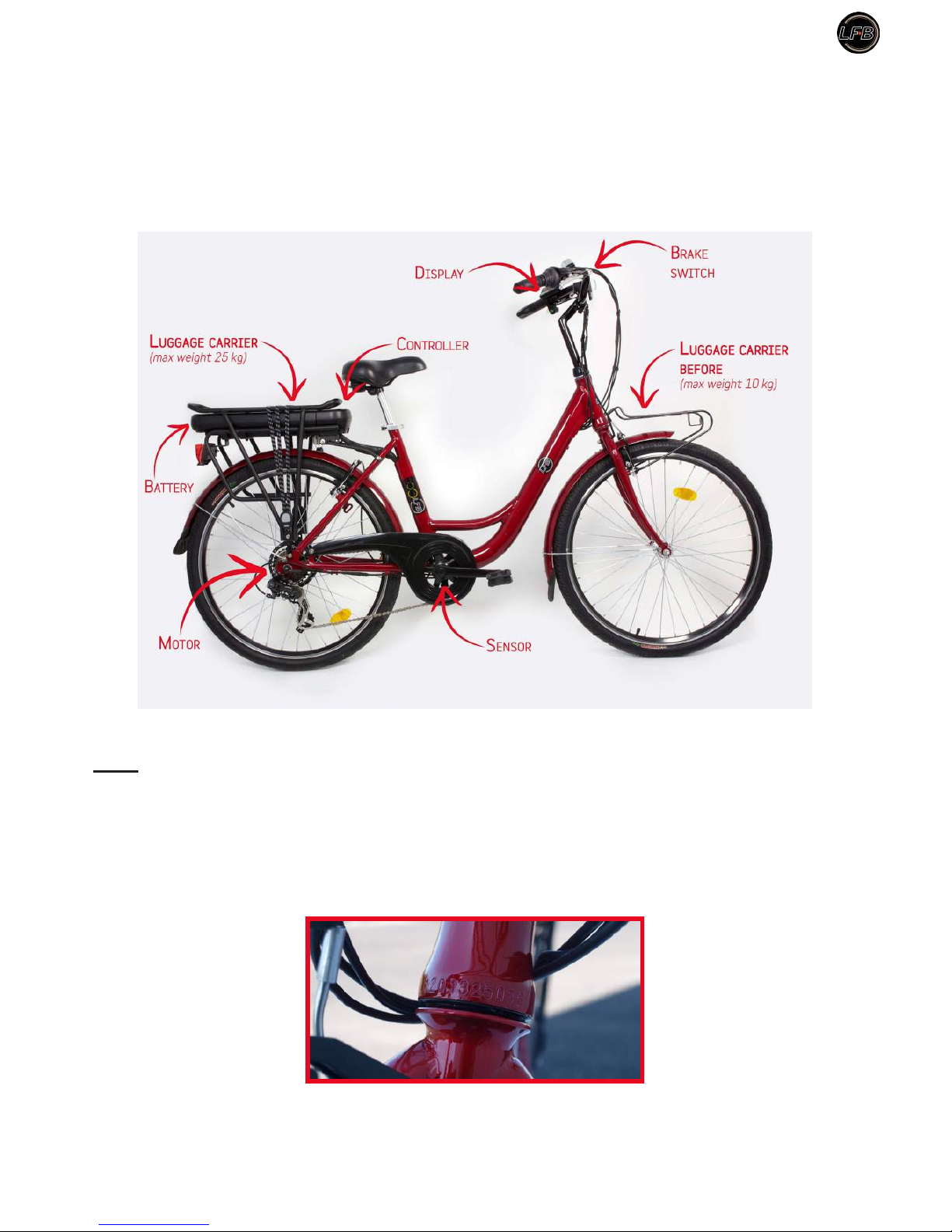
1. PRESENTATION........................................................................................................................................5
2. SETTINGS / INSTALLATION..................................................................................................................6
2.1 Saddle settings........................................................................................................................................6
2.1.1 Angle.............................................................................................................................................6
2.1.2 Height............................................................................................................................................6
2.2 Handlebar adjustement
(handlebars and stem)
.......................................................................................7
2.2.1 Height............................................................................................................................................7
2.3 Brake adjustment.....................................................................................................................................8
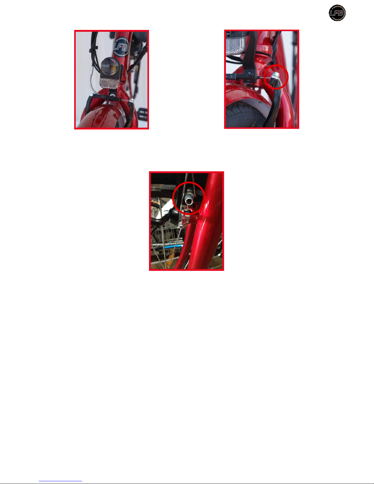
2.3.1 Front brake Type V-Brake..............................................................................................................8
2.3.2 Rear Brake Type V-Brake..............................................................................................................9
2.4 Luggage carrier......................................................................................................................................10
2.5Assembly and disassembly wheels
(rear wheel by specialist)
...............................................................11
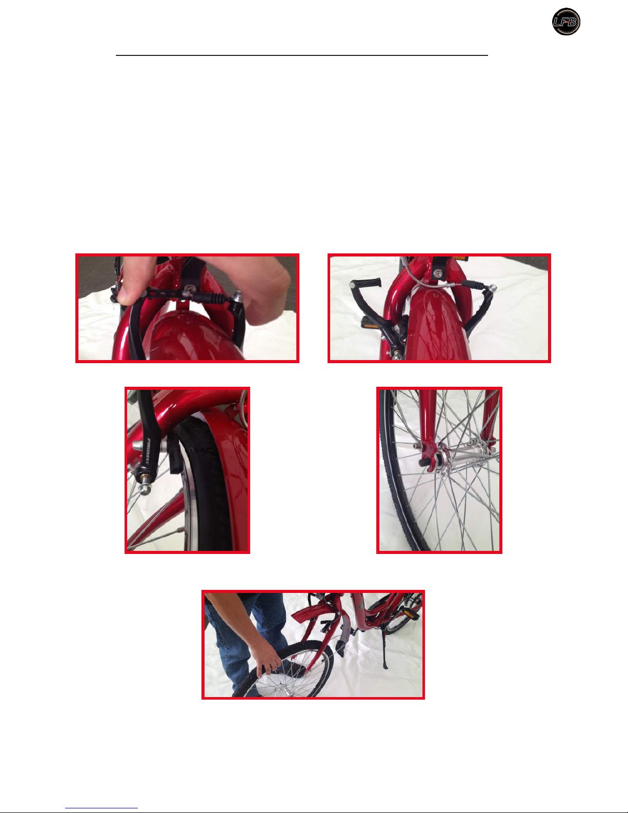
2.5.1 Front wheel..................................................................................................................................11
2.5.2 Rear wheel...................................................................................................................................12
2.6 Lighting.................................................................................................................................................15
3. USEOFANEBIKE....................................................................................................................................17
3.1 Change speeds indexed..........................................................................................................................17
3.2 Change speeds electronic......................................................................................................................17
3.3 The battery meter...................................................................................................................................18
3.4 The electric assistance...........................................................................................................................18
3.4.1 Operation.....................................................................................................................................18
3.4.2 Performances...............................................................................................................................19
3.4.3 Technical specications of the assistance system........................................................................19
3.4.4 Starting and the locking of the battery.........................................................................................19
3.5 The electric motor..................................................................................................................................20
4. BATTERYCHARGE.................................................................................................................................21
4.1 Charger..................................................................................................................................................21
4.1.1 Precautions
(safety instructions)
..................................................................................................22
4.1.2 Charger protection.......................................................................................................................22
4.2 The battery.............................................................................................................................................23
4.2.1 Safety recommendations with your battery..................................................................................24
5. TIPSFOR INCREASEDAUTONOMY...................................................................................................26
6. CT26-15 MAINTENANCE.......................................................................................................................27
6.1 Maintenance..........................................................................................................................................27
6.2 Lubrication............................................................................................................................................27
6.3 Maintenance..........................................................................................................................................27

Manual CT26-15 - LFB
4
7. SAFETY–RECOMMENDATIONS........................................................................................................28
8. TECHNICALDATA..................................................................................................................................29
9. EC CONFORMITY STATEMENT..........................................................................................................30
10. WARRANTY CONDITIONS............................................................................................................31
11. WARRANTYCERTIFICATE...........................................................................................................32
12. CONFORMITY CERTIFICATE......................................................................................................33

Manual CT26-15 - LFB
5
1. PRESENTATION
Thank you for choosing an ebike LFB.
Presentation of ebike
Note:
• The sign rindicates important tips and mandatory safety measures. Follow the various instructions.
• Some adjustments, assembly / disassembly tool and require a particular skill; will perform as if you are
experienced, otherwise consult your authorized dealer or specialist.
• The sign indicates the tools that will be needed for setting operations.
• Your electric bike has a serial number engraved on the frame just above the fork.
Serial number engraved on the frame just above the fork.
r
MaxiMuM load: 100 kg. For your saFety it is necessary to not put aload higher on the ebike when you are
riding it.

Manual CT26-15 - LFB
6
2. SETTINGS / INSTALLATION
r
adapt the bike to your size.
2.1 Saddle settings
Key 13 mm.
2.1.1Angle
Nut.
Loosen the nut under the saddle.
Adjust the angle of the saddle, in order to get the best for your comfort position. Tighten the nut (tightening
torque 25 Nm).
2.1.2Height
The ebike saddle enables a lower position than on a conventional bike. With the electric assistance you will
provide less effort and you can be sitted at a lower position for better safety. The required sizes of the user
(rider) for optimum use of the bicycle is between 1.50 and 1.90m. So, adjust your seating position seat height
according to the following indications:
Loosen the quick release of the saddle tube.
Quick release.
Sitting on the saddle with shoes suitable for cycling, place a pedal in the down position, place one heel on
the pedal, the leg must fall normally without being stiff. Raise or lower the saddle to get the correct height.

Manual CT26-15 - LFB
7
By pedaling backwards you should not wiggle.
To calculate the height, you can also the formula «saddle height» = 0.885 x «crotch». To measure the
crotch height put yourself barefoot and spaced beads ve centimeters. Place (without pressing too hard) a
stick against your perineum and then measure the height from the oor to the stick. You then get the value
«crotch».
Fasten the quick release.
r
the saddle tube should not coMe out beyond the etched saFety Mark (vertical bars).
Safety Mark.
The minimum height between the highest point of the saddle and the soil is 80 cm.
2.2 Handlebar adjustement (handlebars and stem)
Allen key 6 mm.
2.2.1 Height
To be comfortable, the position of your handlebars should be at least at the same height as your saddle, or
more depending on your comfort. Unscrew the Allen screw and set the desired height of your handlebars.
Screw height adjustment. Handlebar angle adjustment screws.
Do the same with the second screw to adjust the angle of your handlebars. After adjustment, vigorously
tighten screws, maximum tightening torque of 25 Nm.

Manual CT26-15 - LFB
8
r
the steM should not coMe out oF the head tube beyond the engraved Mark (vertical bars and inscription
«MINIMUM INSERTION»).
After adjustment, tighten the screw by turning clockwise direction (maximum tightening torque of 25 Nm).
2.3 Brake adjustment
Allen key 5 mm.
Screwdriver.
2.3.1 Front brake Type V-Brake
The front brake is maneuvered by the left handle on the handlebar.
Fully tighten the nut on the brake lever, this feature allows you to compensate later the natural release of
the brake cable.
Loosen the cable clamp and pull the cable until the brake pads touch the rim. Tighten the cable clamp (special
attention is to be made at each end of the sheath which is to enter without forcing into the housing of each
rigid tip, brake lever and V-Brake).

Manual CT26-15 - LFB
9
The pads are properly adjusted when they are equidistant from the rim. The nal adjustment is to tighten
the screws mounted on brake holders with a screwdriver (distance of approximately 0.1 to 0.5 mm from the
rim).
Controlling your setting is correct when the wheel freely rotates and stops smoothly.
2.3.2Rear Brake Type V-Brake
The rear brake is operated by the right handle to the handlebar.
As for the front brake (See: 2.3.1) fully tighten the nut on the brake lever, this feature allows you to
compensate later the natural release of the brake cable.
Loosen the cable clamp (See: photos of the front brake control) and pull the cable until the brake pads
touch the rim.
Tighten the cable clamp (special attention is to be made at each end of the sheath which is to enter without
forcing into the housing of each rigid tip, brake lever and V Brake.)
The pads are properly adjusted when they are equidistant from the rim. The nal adjustment is to tighten the
screws mounted on shoe holder with a screwdriver (distance of approximately 0.1 to 0.5 mm from the rim).
r
warning! when rainning or on wet surFaces, the stopping distance increases.

Manual CT26-15 - LFB
10
2.4 Luggage carrier
r
donot charge More than
10 KG
on the
FRONT CARRIER.
r
donot load your
REAR CARRIER
More than the value indicated:
25 KG.
All devices device or luggage installed by you on your carrier (child seat - other luggage, etc.) must be
compatible with the geometric characteristics and resistance of the bicycle.
r
you Must periodically control that the screws Fixing the carrier are tightened. this type oF carrier is
not designed to tow trailers.
Any changes made on the carrier by the user will engage its own responsibility.
When the carrier is loaded, cycling behavior changes are to be considered (wind stability, braking distances,
changing directions etc ...). For his safety, the user must be aware of these behavioral changes.
When installing a child seat or saddle bags, a security control is required (straps dangling, danger-taking in
the rays, fall to fear, seat xing child to check stability, risk pinch of the ngers of the child under the saddle,
etc.).
The reector and the rear trafc light should not be hidden by luggage or seat attached to the carrier.
The load on the luggage carrier shall be distributed on each side thereof in order to ensure stability during
movement on public roads.

Manual CT26-15 - LFB
11
2.5 Assembly and disassembly wheels
(rear wheel by specialist)
2.5.1 Front wheel
Wrench 15 mm.
Disassembly the front wheel :
You must rst loosen the cable clamp of the V-Brake to release the pads in order to remove the wheel. Loosen
the nuts on each side of the axis of the wheel and release the washers.
Lift the bike and lightly hit the top of the tire to clear the wheel.
Loosen the cable clamp brake V-Brake.
Released pads. Loosen the nuts on each side of the axis of
the wheel.
Lift the bike to remove the wheel.

Manual CT26-15 - LFB
12
Assembly the front wheel:
Position the washers on the wheel axle. Lift the bike and insert the wheel spindle in the bottom of the legs
of the fork.
Control the washers position as well as the centering of the wheel. Screw the wheel nuts. Alternately on each
side gradually tighten the wheel nuts (tightening 18-25 Nm).
If the wheel is not centered, loosen nuts and start again.
r
donot touch the sMall nuts oF the axle
,
you May daMage May daMage the bearings.
Adjust your brake again (See: 2.3).
2.5.2Rear wheel
r
this operation is to be perForMed by aproFessional, but in case you would like to do it,here is the
procedure to Follow.
Required tools: wrench of 19 mm.
Disassembly of the rear wheel:
Disconnect the motor (located right side of the connection ebike on the lower horizontal part of the frame).
Cut «Colson» link xing the motor cable to the frame. Remove nuts caches right and left. Loosen the nuts.
Remove the nuts and wheel axle washers. Loosen the brake cable V-Brake clamp to release the pads in order
to remove the wheel.
Release the chain sprocket wheel with special attention to the tilting of the chain.
Remove the wheel from the frame forward and remove the chain wheel axis.

Manual CT26-15 - LFB
13
Assembly of the rear wheel:
Take the wheel and put the chain on the smallest sprocket right side, then engage the wheel between the
brake pads.
r
warning ! the Motor shaFt has an axle with 2 Flat sides. itshould be positioned to allow it to pass in the
FraMe. todo this it is soMetiMes necessary to rotate the axle.
Flat sie of the axle Passage frame.
Returning to the back, insert the wheel axle in the housing right and left of the frame. Put washers and wheel
nuts. Tighten the nuts by hand at rst so they touch the frame.
r
warning ! oneach side there is awasher with Flat «pin». the pin should always be positioned in the
openings oF the FraMe to prevent the axle FroM turning on itselF.
Washer with at pin.
To prevent the motor rotates the axle and not
the wheel, ensure that the pin is locked in the
frame.
Center the wheel in the frame. Control the centering and positioning in line with the front wheel, and the
positioning of the chain.
Screw without tighten wheel nuts on each side. Recheck the positioning, centering and position of the chain.
Tighten alternately and gradually on each side of the wheel the nuts (tightening torque 40 Nm max). Replace
nuts caches.
Flat pin
Flat sie
of the
axle.
Flat sie
of the
axle.

Manual CT26-15 - LFB
14
Connect the motor cable and replace «Colson» xation (new one) on frame.
NB: The motor connector cable has keyed. Put the two arrows one in front of each other to properly
reconnect the motor.
Position the two arrows one in front of the other to reconnect the motor plug.
Adjust the brake pads (See: 2.3.2).

Manual CT26-15 - LFB
15
2.6 Lighting
Your bike is supplied with:
vFront light with dry battery (2 batteries type C32032 3V) that lights up by the switch under:
ON / OFF switch.
To change the batteries of the front lamp:
Unscrew the front of the lamp and pull it out toward you.

Manual CT26-15 - LFB
16
vA red rear lamp with dry battery (2 batteries AAA) that light by the switch on the left side:
ON / OFF switch.
To change the batteries of lamp:
Press the black plastic where it is written
«BASTA».
r
always keep your own lighting clean and in good condition.
r
a lighting equipMent is Mandatory at nightFall.

Manual CT26-15 - LFB
17
3. USE OF AN EBIKE
3.1 Change speeds indexed
Your ebike has 6 gears, with a derailleur (6 sprockets) and a gear lever.
v 1 sprocket of 14 teeth (great development) that allows you, in easy congurations (downhill, at, etc),
to increase your speed ;
v3 intermediates sprockets of 16, 18, 21 teeth to use in a normal situation ;
v2 sprockets « small development » to 24 et 28 teeth for tough hills and starts.
The twist grip gear lever is on the right of the handlebar, operate it to select one of 6 preset positions. Turn
down to «descend» the gears (6-1) and turn upward to «mount» the gears (1-6).
3.2 Change speeds electronic
Your bike is equipped with 4 electronic assists:
1) Assistance set at 6 km/h that lets you start effortlessly. We must hold down the button 6km/h and
this starts your ebike without pedaling up to the speed of 6km/h;
2) LOW (on the left) = economic position. In this position your ebike uses less power;
3) MED (centre) = average assistance position;
4) HIGH (on the right) = maximum assistance. In this position your ebike provides the greatest
assistance, but also consumes the most energy.
To select assistance (L, M, H), press the «Mode» button.
The assistance selector is located on the left side of the handlebar below the button «ON / OFF».
«MODE» button. Assistance set at 6 km/h.

Manual CT26-15 - LFB
18
3.3 The battery meter
This gauge is on the display with the assistance selector.
Load indicator.
When switched on the differents the lights of the display successively light for a reading test, and stabilized
thereafter. Located on the left side of the handlebar, all gauge / selector is in range of your view. Initially with
a charged battery, all LEDs of the gauge are red. You can control the remaining energy and adapt your pace
and your assistance mode.
3.4 The electric assistance
3.4.1 Operation
Your ebike is a bike with electric assistance: it is equipped with an electric motor in the rear wheel. This
engine starts automatically (if the display is on and the battery charged) when you pedal and only when you
pedal.
The assistance is provided by an electromagnetic sensor that cuts power to the motor when the pedal stops
rotating.
The motor also switches off when:
• You press one of the two brakes;
• You reach the speed limit of 25 km / h.
This principle allows the engine to give you full power when you need it and make «energy savings» when
you’re going downhill or pedaling on a at road.
This energy management allows to offer a greater autonomy. These functions and energy management are
performed by an electronic box or «controller».
r
weinForM you that when on or oFF the assistance May result in acceleration or deceleration in spurts.

Manual CT26-15 - LFB
19
3.4.2 Performances
The rate of assistance of your bike is limited to 25 km / h.
At this speed the motor switches off automatically.
The autonomy of your ebike depends on several parameters:
vThe carrying weight:
The performance of your bike are given for an average load of 75 kg.
vThe outside temperature:
Performance is given for an outer temperature of about 20 ° C. Below this temperature performance
decreases. However, this decline is really signicant below 5 ° C.
vThe wear of battery:
Your battery is designed to deliver you stable performances for 600 charge cycles (or an average use of 3
years). After these 600 cycles, it is still operational, but its performance and therefore your range, decrease
proportionately.
vBut above all the autonomy depends on the nature of your journey:
The theoretical range of 45-55 km is for a near-continuous sollicitation of the engine on a at surface or
slightly up hill (10-20% of slop). If your course is at and includes a percentage of down hill (even minor),
your range is enhanced and can go up to 65 km. If you mount slop of more than 5% (the engine «suffers»
above 8% slop), your autonomy may decrease proportionally.
3.4.3 Technical specications of the assistance system
Motor: Brushless type - 250 watts
Battery: Lithium Ion 37V - 10AH - Life cycle: 600 full charge / discharge cycles under normal load condition
Autonomy: 55 km for 10Ah battery
(For someone of 75Kg with the ECO assist level).
3.4.4 Starting and the locking of the battery
The starting and stopping of the battery are controlled using the button «ON / OFF» of the display on the
handlebar.

Manual CT26-15 - LFB
20
Your battery is locked by a locking key.
3.5 The electric motor
Located in the hub of the rear wheel, it is a brushless electric motor of 250 watts.
It requires no maintenance from your part and has a manufacturer’s warranty of 2 years. After 3 years or 25
000 km, we advise you to have it inspected by an authorized dealer or specialist.
Although it is designed to resist water, it must never be washed with high pressure water. You may damage
it. This moreover will void the warranty.
Motor.

Manual CT26-15 - LFB
21
4. BATTERY CHARGE
4.1 Charger
USER MANUAL
LITHIUM ION CHARGER 37 volts
BEFORE USING FOR YOUR COMFORT AND SAFETY
READ CAREFULLY
SPECIFICATION
Lithium Ion Charger 37 volts.
The charger that comes with your bike complies with CE manufacturing standards, and environmental
protection standards IEC / EN 60335-1. It has been designed to charge the battery of your electric bike. It
will recharge your battery fully in 4-8 hours according to room temperature and wear off the battery. This
charging time, said «slow», is voluntary in order to preserve the life of your battery.
37 volts model SSLC084V42X
Intelligent charger for Lithium Ion battery
Input voltage AC100 -240 V
Frequency 47-63 hz
Charge voltage 42 V
Output current 2.0 A
RED light on In charge
GREEN light on Battery fully charged
Efciency (at full load) 100 %
Temperature of working Between 0 ° C and 40 ° C.
Humidity <+ 90 %
Safety norm EN60335 –1- A2 –2006
Weight 446 g
Dimensions 165x73x47 mm
Table of contents