manuals.online logo
Brands
  1. Home
  2. •
  3. Brands
  4. •
  5. Cooper
  6. •
  7. Power Supply
  8. •
  9. Cooper Greengate DLVP User manual

Cooper Greengate DLVP User manual

Quick Start Guide Greengate
NOTICE: Designed for indoor installation and use only. Dry location rated.
IMPORTANT SAFEGUARDS
When using electrical equipment, basic safety precautions should always be followed including the following:
a) READ AND FOLLOW ALL SAFETY INSTRUCTIONS.
b) Do not use outdoors (this item may be omitted if the product is suitable for outdoor use).
c) Do not let power supply cords touch hot surfaces.
d) Do not mount near gas or electric heaters.
e) Use caution when servicing batteries. Battery acid can cause burns to skin and eyes. If acid is spilled on skin or in eyes, flush acid with
fresh water and contact a physician immediately.
f) Equipment should be mounted in locations and at heights where it will not readily be subjected to tampering by unauthorized personnel.
g) The use of accessory equipment not recommended by the manufacturer may cause an unsafe condition.
h) Caution: Halogen cycle lamp(s) are used in this equipment. To avoid shattering: Do not operate lamp in excess of rated voltage, protect
lamp against abrasion and scratches and against liquids when lamp is operating, dispose of lamp with care.
i) Halogen cycle lamps operate at high temperatures. Do not store or place flammable materials near lamp.
j) Do not use this equipment for other than intended use.
SAVE THESE INSTRUCTIONS
WARNING
Risk of Fire, Electrical Shock, Cuts or other Casualty Hazards- Installation and maintenance of this product must be
performed by a qualified electrician. This product must be installed in accordance with the applicable installation code
by a person familiar with the construction and operation of the product and hazards involved. For continued protection
against shock hazard replace all covers and guards after field wiring is completed.
Risk of Fire and Electric Shock- Before installing or performing any service, the power MUST be
turned OFF. All installations should be in compliance with the National Electric Code and all state
and local codes.
Risk of Burn- Disconnect power and allow fixture to cool before handling or servicing.
Risk of Personal Injury- Due to sharp edges, handle with care. Failure to comply with these instructions may result in
serious injury (including death) and property damage. Use caution when handling the wallstation while the faceplate is
removed.
DISCLAIMER OF LIABILITY: Cooper Lighting Solutions assumes no liability for damages or losses of any kind that may arise from
the improper, careless, or negligent installation, handling or use of this product.
IMPORTANT: Read carefully before installing fixture. Retain for future reference.
NOTICE: Fixture may become damaged and/or unstable if not installed properly.
Note: Specifications and dimensions subject to change without notice.
ATTENTION Receiving Department: Note actual fixture description of any shortage or noticeable damage on delivery receipt.
File claim for common carrier (LTL) directly with carrier. Claims for concealed damage must be filed within 15 days of delivery.
All damaged material, complete with original packing must be retained.
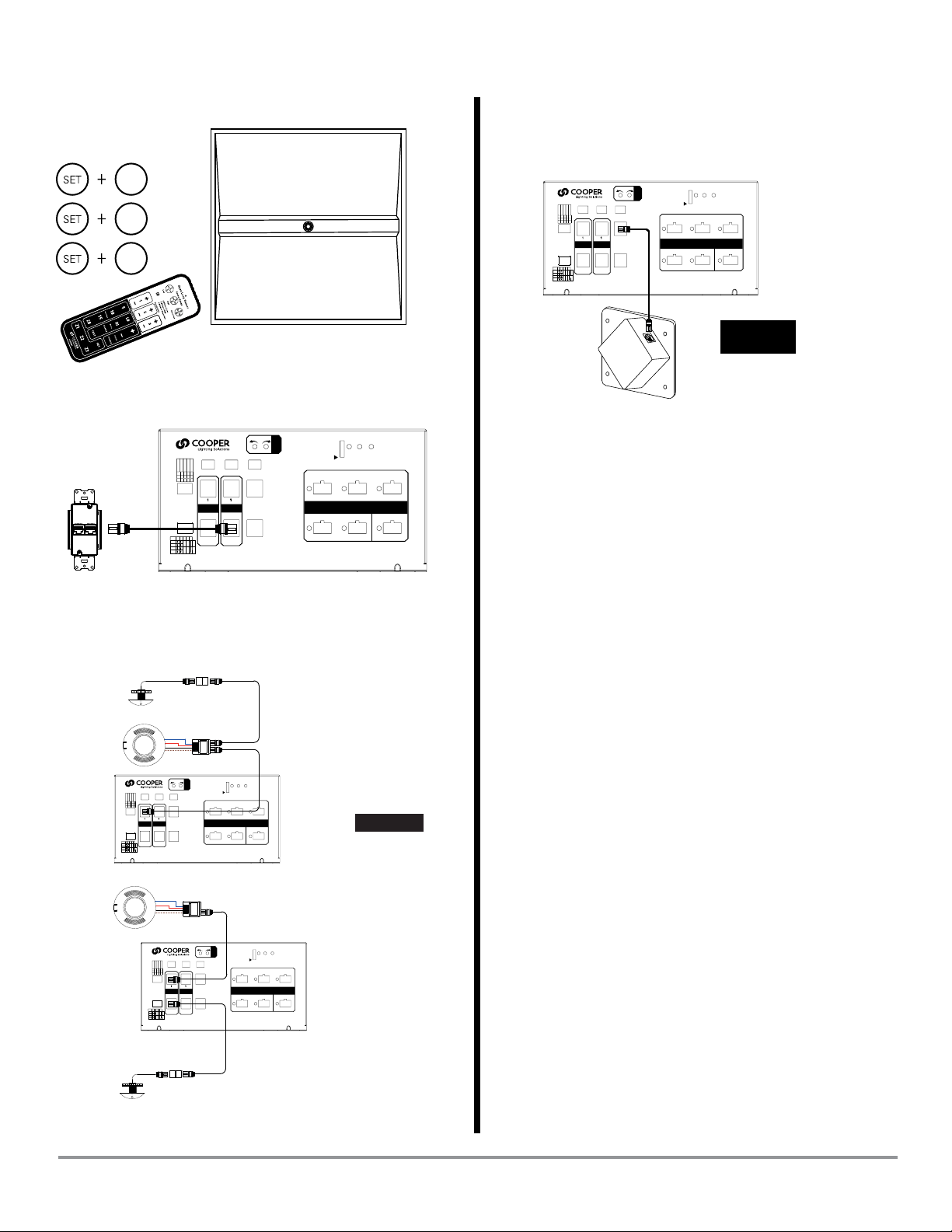
DLVP - Distributed Low Voltage Power System
IB503030EN page 2
June 2020
www.cooperlighting.com
Quick Start GuideGreengate - Distributed Low-Voltage Power System
1. Mount Low-Voltage Power Module
Min. 3”
(75mm)
Min. 24”
(600mm) Min. 12”
(300mm)
2. Provide Power
All new wiring must be fully verified before applying power.
emergency power
connection
remove divider and wire internally
when NOT using EM panel
Note: LVPM-03-100-03 and LVPM-06-100-03 do not have emergency inputs
normal power
connection
Normal Power Input EM Power Input
120VAC 277VAC 120VAC 277VAC
LVPM-03-100-03-1E 1.76 0.76 0.88 0.38
LVPM-06-100-03-1E 4.40 1.90 0.88 0.38
3. Congure Power Module
+ - + - + -
DEMAND CLOCK ALERT
LOW
HIGH
1 1 REC
BMS/OUT
2 2 SWITCH
PAC K
WALLSENSORS
12 3 4 5
V Y
ON
Occ / Vac
Partial On
Y
N
Y
N
Select Occ
Occ Share
F
S
Auto On
DEFAULT
10%
1
20%
30%
40%
2 3 4 5
DIAGNORM
DIP Switch Set A
Switch # / Mode Position Operation
1 / Occupancy VVacancy
OOccupancy
2 / Partial ON YPartial ON 50%
NScene 6
3 Selectable Occupancy YBy Zone
NBy Space
4 Occupancy Sharing YShare Sensor
NNo Sharing
5 Scheduled Level FFixed to Full / Off
DDefault Configured Scenes
4. Connect Fixtures
STATUS
TEST
RESET
4 5 6
1 2
EMERGENCY
3
LOW-VOLTAGE OUTPUTS
SUITABLE FOR CLASS 2WIRING
LL503018EN
57VDC 90W MAX (EACH OUTPUT)
CAUTION: DO NOT OVERLOAD
+ - + - + -
DEMAND CLOCK ALERT
LOW HIGH
TRIM
1 1 REC
BMS/OUT
2 2 SWITCH
PAC K
WALLSENSORS
12345
V Y
ON
Occ / Vac
PartialOn
Y
N
Y
N
Select Occ
Occ Share
F
S
Auto On
DEFAULT
10%
1
20%
30%
40%
2 3 4 5
DIAGNORM
90W MAX
per LV output
circuit
Low-voltage
lighting cable
5. Fixture Zone Assignment
1 2 3 4 5 6
Zone 3
O
N
1 2 3 4 5 6
Zone 2
O
N
1 2 3 4 5 6
Zone 1
O
N
ote:N Zone 1 is any DIP switch configuration that is not specifically
zone 2 or zone 3.
ote:N During normal operation, avoid setting all DIP switches to the
ON position.
IB503030EN page 3
June 2020
www.cooperlighting.com
Quick Start Guide Greengate - Distributed Low-Voltage Power System
OR:
Z1
Z2
Z3
= zone 1
= zone 2
= zone 3
6. Connect Wallstations (up to 12)
STATUS
TEST
RESET
4 5 6
1 2
EMERGENCY
3
LOW-VOLTAGE OUTPUTS
SUITABLE FOR CLASS 2 WIRING
LL503018EN
57VDC 90W MAX (EACH OUTPUT)
CAUTION: DO NOT OVERLOAD
+ - + - + -
DEMAND CLOCK ALERT
LOW HIGH
TRIM
1 1 REC
BMS/OUT
2 2 SWITCH
PAC K
WALLSENSORS
12 3 4 5
V Y
ON
Occ / Vac
Partial On
Y
N
Y
N
Select Occ
Occ Share
F
S
Auto On
DEFAULT
10%
1
20%
30%
40%
2 3 4 5
DIAGNORM
Pre-terminated
control cable
7. Connect Sensors
(2 Occupancy / 1 Daylight)
Pre-terminated
control cable
Pre-terminated
control cable
GGRC-COUPLER
(Daylight Sensor Coupler)
OCC-RJ45
(Input/Output Device)
OCC-RJ45
(Input/Output Device)
GGRC-COUPLER
(Daylight Sensor Coupler)
STATUS
TEST
RESET
4 5 6
1 2
EMERGENCY
3
LOW-VOLTAGEOUTPUTS
SUITABLE FOR CLASS2 WIRING
LL503018EN
57VDC 90W MAX (EACH OUTPUT)
CAUTION: DO NOT OVERLOAD
+ - + - + -
DEMAND CLOCK ALERT
LOW HIGH
TRIM
1 1 REC
BMS/OUT
2 2 SWITCH
PAC K
WALLSENSORS
12 3 4 5
V Y
ON
Occ/ Vac
PartialOn
Y
N
Y
N
SelectOcc
OccShare
F
S
AutoOn
DEFAULT
10%
1
20%
30%
40%
2 3 4 5
DIAGNORM
Model:OCC-RJ45
OccupancySensor Coupler
Brown
Black
Red
Blue
Model:OCC-RJ45
OccupancySensor Coupler
Brown
Black
Red
Blue
STATUS
TEST
RESET
4 5 6
1 2
EMERGENCY
3
LOW-VOLTAGEOUTPUTS
SUITABLE FOR CLASS2 WIRING
LL503018EN
57VDC 90W MAX (EACH OUTPUT)
CAUTION: DO NOT OVERLOAD
+ - + - + -
DEMAND CLOCK ALERT
LOW HIGH
TRIM
1 1 REC
BMS/OUT
2 2 SWITCH
PAC K
WALLSENSORS
12 3 4 5
V Y
ON
Occ/ Vac
PartialOn
Y
N
Y
N
SelectOcc
OccShare
F
S
AutoOn
DEFAULT
10%
1
20%
30%
40%
2 3 4 5
DIAGNORM
Model:OCC-RJ45
OccupancySensor Coupler
Brown
Black
Red
Blue
Model:OCC-RJ45
OccupancySensor Coupler
Brown
Black
Red
Blue
OR:
port
SENSOR
8. Connect Receptacle Switchpack
(up to 5)
STATUS
TEST
RESET
4 5 6
1 2
EMERGENCY
3
LOW-VOLTAGE OUTPUTS
SUITABLE FOR CLASS 2WIRING
LL503018EN
57VDC 90W MAX (EACH OUTPUT)
CAUTION: DO NOT OVERLOAD
+ - + - + -
DEMAND CLOCK ALERT
LOW HIGH
TRIM
1 1 REC
BMS/OUT
2 2 SWITCH
PAC K
WALLSENSORS
12 3 45
V Y
ON
Occ / Vac
Partial On
Y
N
Y
N
Select Occ
Occ Share
F
S
Auto On
DEFAULT
10%
1
20%
30%
40%
2 3 4 5
DIAGNORM
Pre-terminated
control cable
port
REC
BMS/OUT
See full instruction manual: cooperlighting.com
Installation videos: YouTube.com
IB503030EN page 4
June 2020
Cooper Lighting Solutions
1121 Highway 74 South
Peachtree City, GA 30269
P: 770-486-4800
www.cooperlighting.com
For service or technical assistance:
1-800-553-3879
Canada Sales
5925 McLaughlin Road
Mississauga, Ontario L5R 1B8
P: 905-501-3000
F: 905-501-3172
© 2020 Cooper Lighting Solutions
All Rights Reserved.
Product availability, specifications,
and compliances are subject to
change without notice.
Quick Start GuideGreengate - Distributed Low-Voltage Power System
Warranties and Limitation of Liability
Please refer to www.cooperlighting.com for our terms and conditions.
Garanties et limitation de responsabilité
Veuillez consulter le site www.cooperlighting.com pour obtenir les conditions générales.
Garantías y Limitación de Responsabilidad
Visite www.cooperlighting.com para conocer nuestros términos y condiciones.

Other Cooper Power Supply manuals

Cooper POWERPATH PS-6 User manual

Cooper

Cooper POWERPATH PS-6 User manual

Cooper DLVP User manual

Cooper

Cooper DLVP User manual

Cooper DVLP Series User manual

Cooper

Cooper DVLP Series User manual

Popular Power Supply manuals by other brands

Emerson Packaged Drives and Engineered Systems brochure

Emerson

Emerson Packaged Drives and Engineered Systems brochure

Scientech Technologies Scientech 4077A Product tutorial

Scientech Technologies

Scientech Technologies Scientech 4077A Product tutorial

Celestron POWER TANK 18774 instruction manual

Celestron

Celestron POWER TANK 18774 instruction manual

Vertiv NetSure 512NGBB user manual

Vertiv

Vertiv NetSure 512NGBB user manual

LITELINE LED-HWB-24V-100W quick start guide

LITELINE

LITELINE LED-HWB-24V-100W quick start guide

C-TEC BF562-1 installation instructions

C-TEC

C-TEC BF562-1 installation instructions

SFC Energy EFOY Pro Series Hints & Tips

SFC Energy

SFC Energy EFOY Pro Series Hints & Tips

Siemens 4AV2306-2EB00-0A operating instructions

Siemens

Siemens 4AV2306-2EB00-0A operating instructions

Altronix ALTV1224DC installation instructions

Altronix

Altronix ALTV1224DC installation instructions

Rohde & Schwarz HM7042-5 manual

Rohde & Schwarz

Rohde & Schwarz HM7042-5 manual

Nordson MPS610V product manual

Nordson

Nordson MPS610V product manual

EnerSys Alpha XRT-TPPL quick start guide

EnerSys

EnerSys Alpha XRT-TPPL quick start guide

Elgar Sorensen DCS Series instruction manual

Elgar

Elgar Sorensen DCS Series instruction manual

National Instruments NI PXI-1006 user guide

National Instruments

National Instruments NI PXI-1006 user guide

EKSMA OPTICS HV-200 manual

EKSMA OPTICS

EKSMA OPTICS HV-200 manual

GreenTech Capess user manual

GreenTech

GreenTech Capess user manual

Endress+Hauser RN 221N operating instructions

Endress+Hauser

Endress+Hauser RN 221N operating instructions

Velleman PS3005D user manual

Velleman

Velleman PS3005D user manual

manuals.online logo
manuals.online logoBrands
  • About & Mission
  • Contact us
  • Privacy Policy
  • Terms and Conditions

Copyright 2025 Manuals.Online. All Rights Reserved.