Safety Unit FSS Español
© CEDES | V 1.0 7
Descripción general
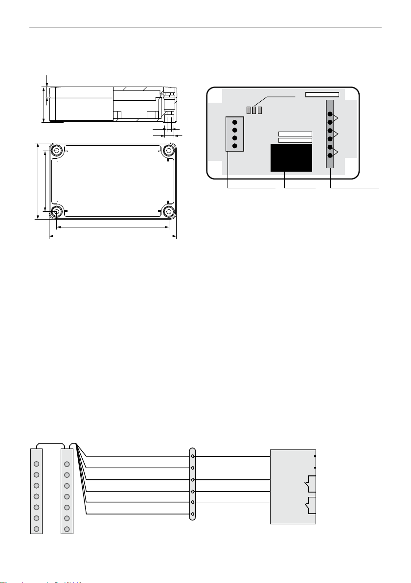
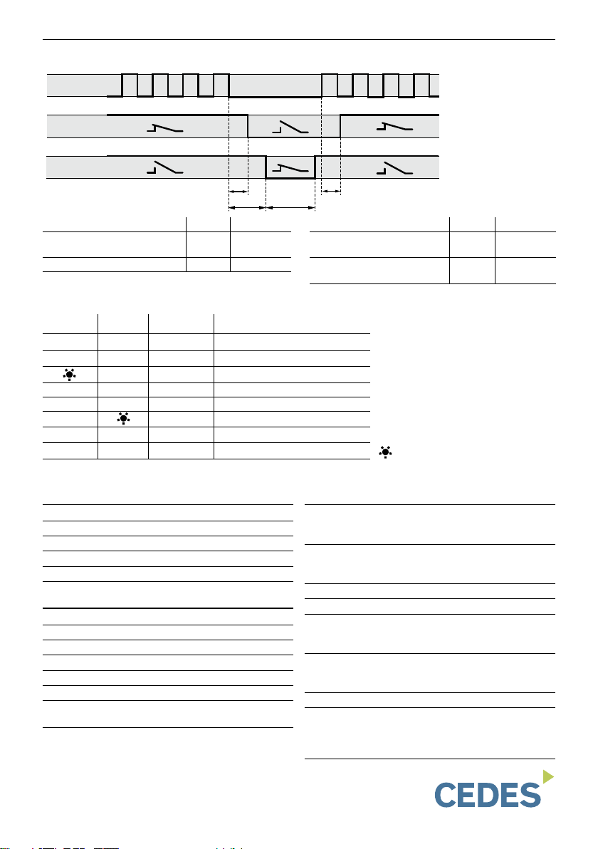
Conexión eléctrica (Ejemplo: GridScan/Mini)
Introducción
El dispositivo Safety Unit FSS ha sido desarrollado como
unidad de supervisión categoría 2, PL D, según EN 13849-
1, para cortinas fotoeléctricas con salida FSS. Junto con la
cortina, el conjunto se puede integrar en cualquier maniobra
de puerta sin entrada de test.
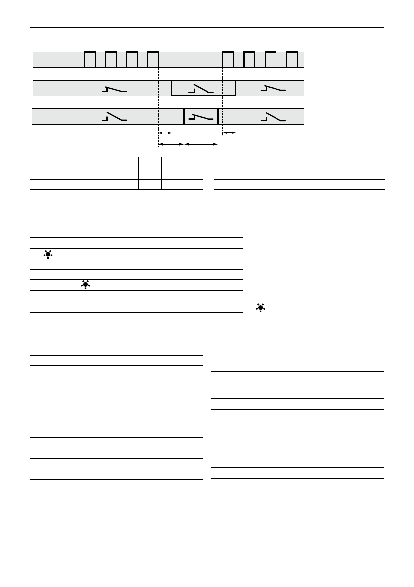
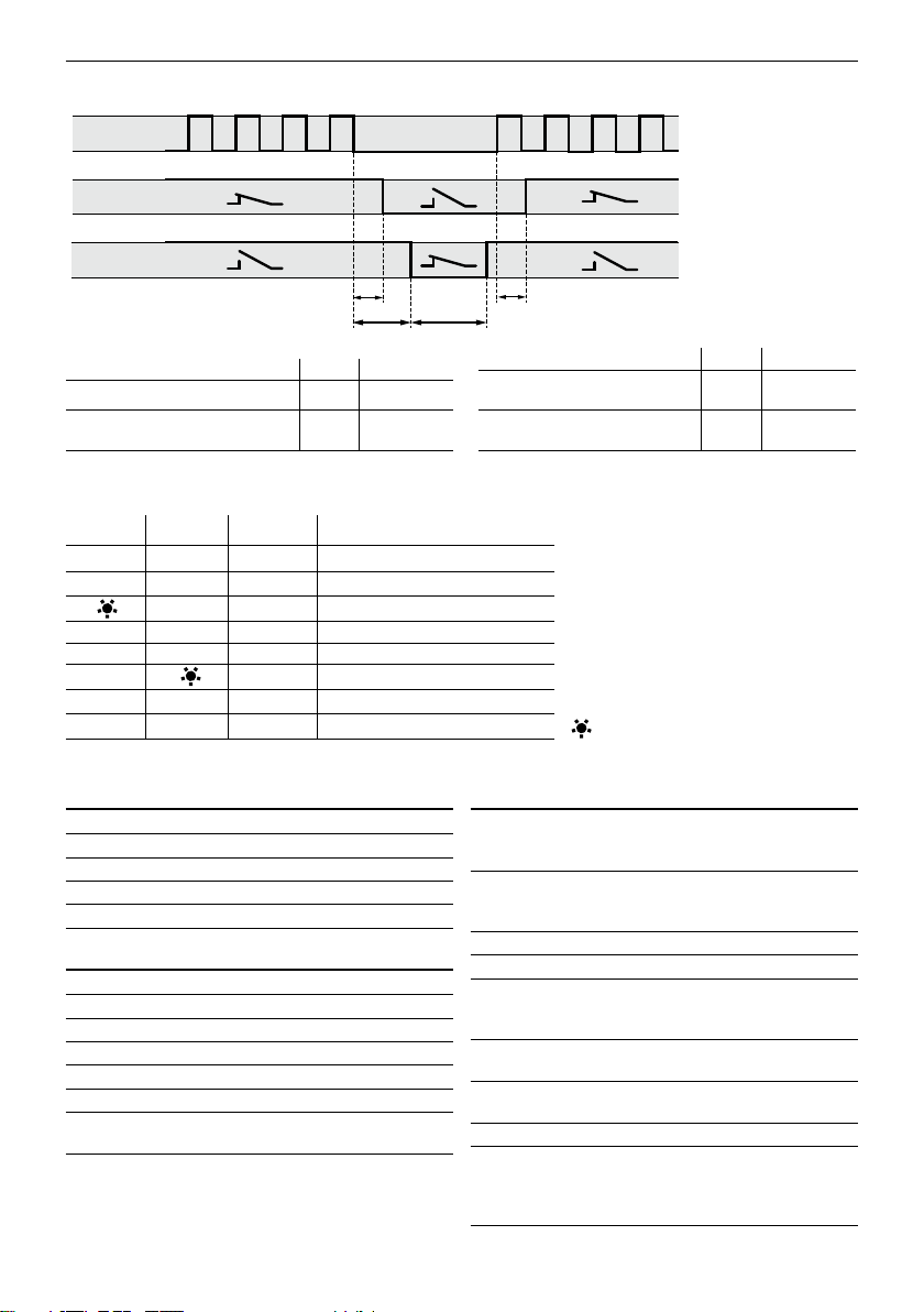
Esta unidad de control dispone de dos salidas; un circuito
de parada y un contacto de inversión. El circuito de parada
funciona como un contacto de seguridad. Este está cerrado
en el momento en el que el dispositivo Safety Unit FSS
reconoce una señal válida en su circuito de entrada. En el
momento en el que ésta señal desaparece o se detecta
cualquier fallo, el contacto de seguridad se abre.
El contacto de inversión se cierra durante 2 segundos en el
momento en el que desaparece la señal FSS en la entrada.
Después de ese tiempo el contacto vuelve a abrir.
Montaje
`Quitar tensión al controlador de la puerta y señalizar
claramente „Puerta fuera de Servicio“.
`Cablear la cortina fotoeléctrica según el esquema de
conexionado.
`Integrar el contacto de seguridad y, si es necesario, el
contacto de inversión en la maniobra.
`Conectar la tensión al regletero de 6 bornes.
`Poner la instalación en marcha.
`Probar el funcionamiento.
!
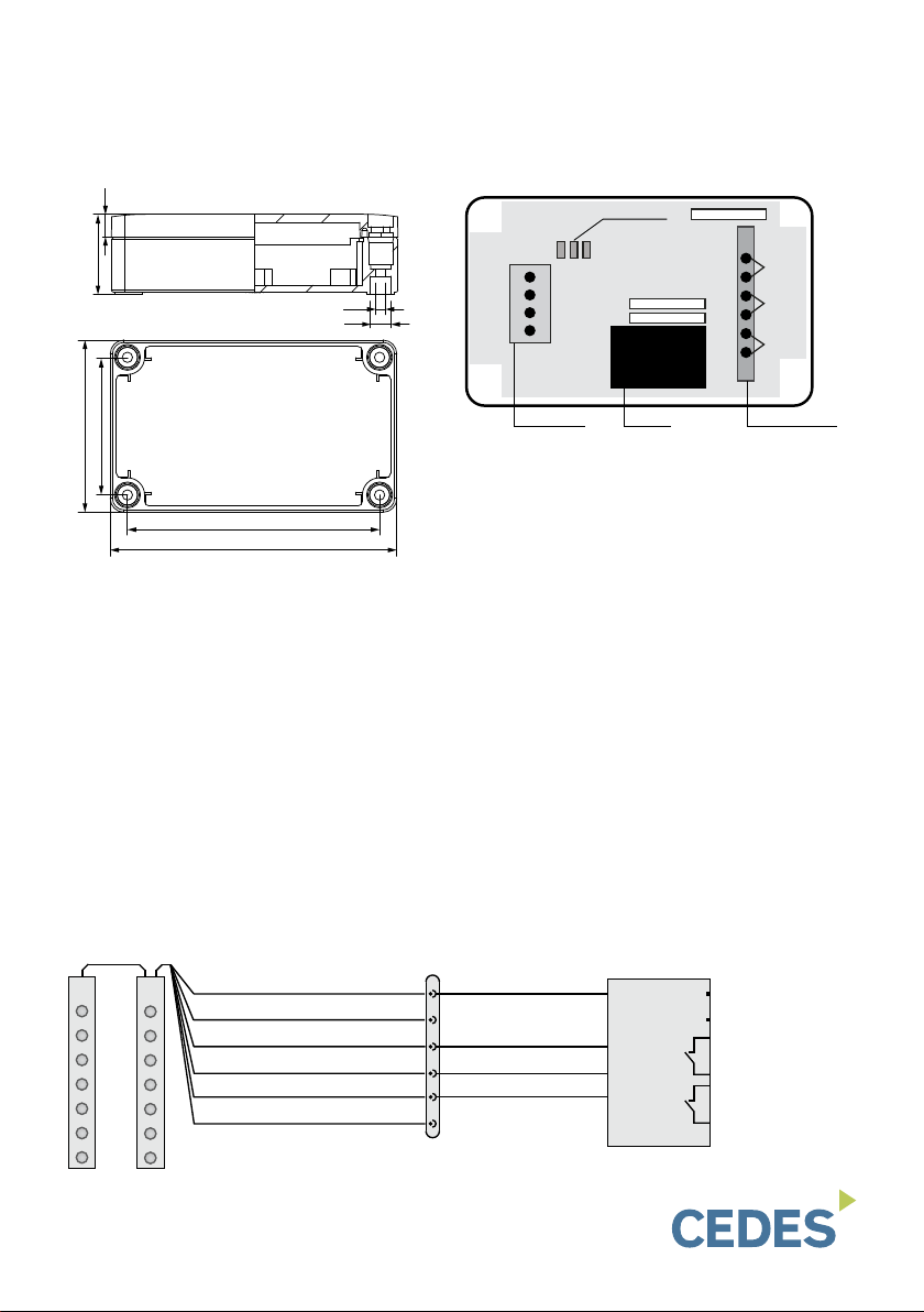
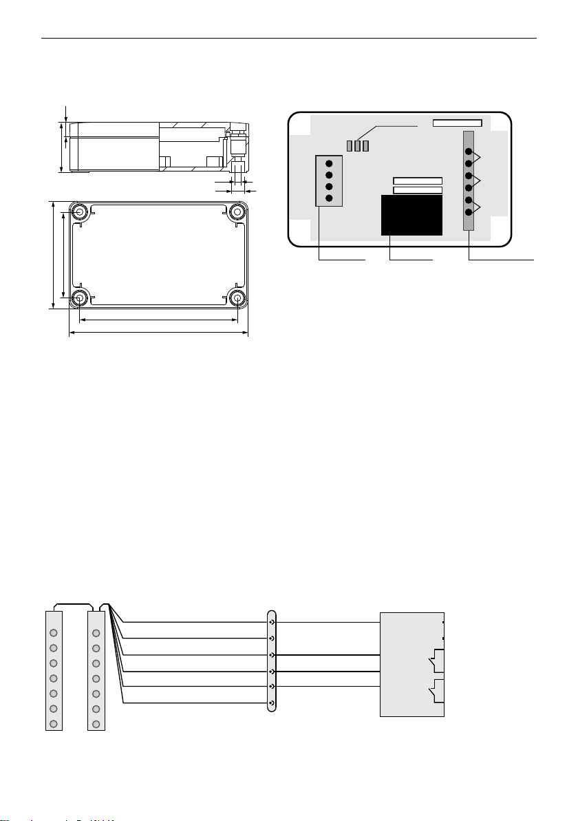
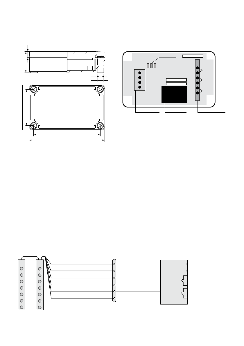
Status LED
Conexionado
cortina fotoeléctrica
Tensión de
alimentación
Regletero hacia
la unidad de control
marrón Rev.
negro
azul
blanco
STOP
Power
4.5
75
125
60
110
9
10
35
5
2
4
3
1
6
Tx Rx
M8, 6-pin Safety Unit FSS
marrón marrón
blanco
negro
azul
L1/+
N/-
gris
negro
blanco
Entrada de test
Sin función
Salida(FSS)
USP perfil
sincronización
GND (0 V)
Sin función
azul
verde
USP
STOP
Rev
Todas las medidas son en mm
La dimensiones no son a escala