PR 2220 User manual

Programmable displays with a wide se-
lection of inputs and outputs for display of temperature,
volume and weight, etc. Feature linearisation, scaling,
and difference measurement functions for programming
via PReset software.
Interfaces for analogue and digital
signals as well as HART®signals between sensors / I/P
converters / frequency signals and control systems in Ex
zone 0, 1 & 2 and for some modules in zone 20, 21 & 22.
Galvanic isolators for analogue and digital
signals as well as HART®signals. A wide product range
with both loop-powered and universal isolators featuring
linearisation, inversion, and scaling of output signals.
PC or front programmable modules with
universal options for input, output and supply. This range
offers a number of advanced features such as process
calibration, linearisation and auto-diagnosis.
A wide selection of transmitters for DIN
form B mounting and DIN rail modules with analogue
and digital bus communication ranging from application-
specific to universal transmitters.
Displays
Temperature
Isolation
Ex interfaces
Universal
DK
UK
FR
DE
Side 1
Page 11
Page 23
Seite 35
SIGNALS THE BEST
2220
Switchmode
Power Supply
No. 2220V102-IN (0942)
From ser. no. 970003001

SWITCHMODE SPÆNDINGSFORSYNING
Type 2220
INDHOLDSFORTEGNELSE
Advarsler . . . . . . . . . . . . . . . . . . . . . . . . . . . . . . . . . . . . . . 2
Sikkerhedsregler . . . . . . . . . . . . . . . . . . . . . . . . . . . . . . . . 3
Overensstemmelseserklæring. . . . . . . . . . . . . . . . . . . . . . 5
Adskillelse af SYSTEM 2200. . . . . . . . . . . . . . . . . . . . . . . 6
Anvendelse . . . . . . . . . . . . . . . . . . . . . . . . . . . . . . . . . . . . 7
Teknisk karakteristik . . . . . . . . . . . . . . . . . . . . . . . . . . . . . 7
Montering . . . . . . . . . . . . . . . . . . . . . . . . . . . . . . . . . . . . . 7
Indgang . . . . . . . . . . . . . . . . . . . . . . . . . . . . . . . . . . . . . . . 7
Udgang . . . . . . . . . . . . . . . . . . . . . . . . . . . . . . . . . . . . . . . 8
Elektriske specifikationer. . . . . . . . . . . . . . . . . . . . . . . . . . 8
Bestillingsskema . . . . . . . . . . . . . . . . . . . . . . . . . . . . . . . . 10
Blokdiagram . . . . . . . . . . . . . . . . . . . . . . . . . . . . . . . . . . . 10
1
SIKKERHEDSREGLER
DEFINITIONER:
Farlige spændinger er defineret som områderne: 75...1500 Volt DC og 50...1000
Volt AC.
Teknikere er kvalificerede personer, som er uddannet eller oplært til at kunne
udføre installation, betjening eller evt. fejlfinding både teknisk og sikkerheds-
mæssigt forsvarligt.
Operatører er personer, som under normal drift med produktet skal indstille og
betjene produktets trykknapper eller potentiometre, og som er gjort bekendt med
indholdet af denne manual.
MODTAGELSE OG UDPAKNING:
Udpak modulet uden at beskadige dette, og sørg for, at manualen altid følger
modulet og er tilgængelig. Indpakningen bør følge modulet, indtil dette er mon-
teret på blivende plads.
Kontrollér ved modtagelsen, at modultypen svarer til den bestilte.
MILJØFORHOLD:
Undgå direkte sollys, kraftigt støv eller varme, mekaniske rystelser og stød, og
udsæt ikke modulet for regn eller kraftig fugt. Om nødvendigt skal opvarmning,
udover de opgivne grænser for omgivelsestemperatur, forhindres ved hjælp af
ventilation.
Alle moduler hører til Installationskategori II, Forureningsgrad 1 og Isolations-
klasse II.
INSTALLATION:
Modulet må kun tilsluttes af teknikere, som er bekendte med de tekniske udtryk,
advarsler og instruktioner i manualen, og som vil følge disse.
Hvis der er tvivl om modulets rette håndtering, skal der rettes henvendelse til den
lokale forhandler eller alternativt direkte til:
PR electronics A/S, Lerbakken 10, DK-8410 Rønde tlf: +45 86 37 26 77.
Installation og tilslutning af modulet skal følge landets gældende regler for instal-
lation af elektrisk materiel bl. a. med hensyn til ledningstværsnit, for-sikring og
placering.
Beskrivelse af indgang / udgang og forsyningsforbindelser findes på blokdia-
grammet og sideskiltet.
For moduler, som er permanent tilsluttet farlig spænding, gælder:
For-sikringens maksimale størrelse er 10 A og skal sammen med en
afbryder placeres let tilgængelig og tæt ved modulet. Afbryderen skal
mærkes således, at der ikke er tvivl om, at den afbryder spændingen til
modulet.
32
ADVARSEL
Dette modul er beregnet for tilslutning til livsfarlige elektriske
spændinger. Hvis denne advarsel ignoreres, kan det føre til alvorlig
legemsbeskadigelse eller mekanisk ødelæggelse. For at undgå
faren for elektriske stød og brand skal manualens sikkerhedsregler
overholdes, og vejledningerne skal følges. De elektriske specifi-
kationer må ikke overskrides, og modulet må kun benyttes som
beskrevet i det følgende. Manualen skal studeres omhyggeligt,
før modulet tages i brug. Kun kvalificeret personale (teknikere) må
installere dette modul. Hvis modulet ikke benyttes som beskrevet i
denne manual, så forringes modulets beskyttelsesforanstaltninger.
ADVARSEL
Der må ikke tilsluttes farlig spænding til modulet, før dette er fast-
monteret, og følgende operationer på modulet bør kun udføres i
spændingsløs tilstand og under ESD-sikre forhold:
Adskillelse af modulet for indstilling af omskiftere og jumpere.
Installation, ledningsmontage og -demontage.
Fejlfinding på modulet.
Reparation af modulet og udskiftning af sikringer må kun
foretages af PR electronics A/S.
ADVARSEL
For at overholde sikkerhedsafstande må moduler med to indbyg-
gede relæer ikke tilsluttes både farlig og ikke-farlig spænding på
samme moduls relækontakter.
SYSTEM 2200 monteres i sokkel type S3B Releco (bestillings-
nummer 7023).
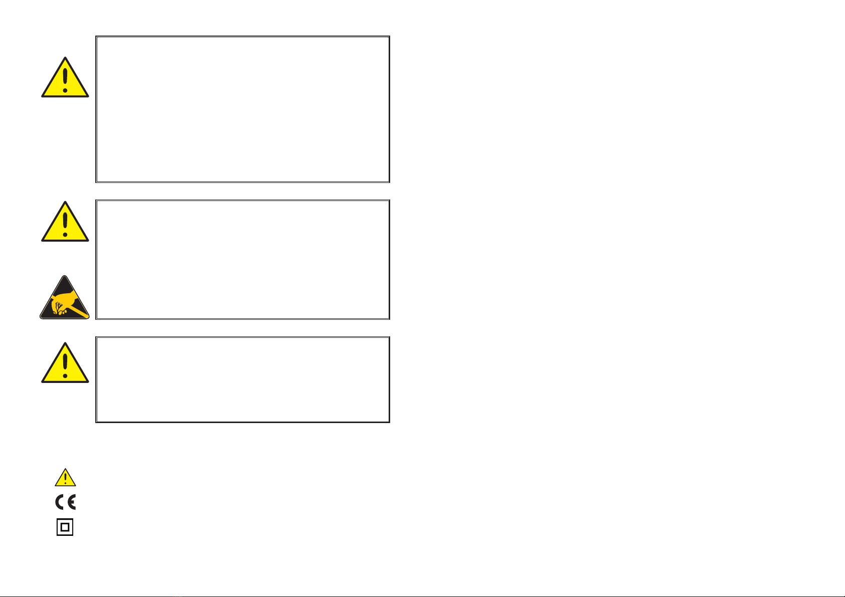
Trekant med udråbstegn: Advarsel / krav. Hændelser der kan
føre til livstruende situationer.
CE-mærket er det synlige tegn på modulets overensstemmelse
med direktivernes krav.
Dobbelt isolation er symbolet for, at modulet overholder ekstra
krav til isolation.
SIGNATURFORKLARING:
FARLIG
SPÆNDING
INSTAL-
LATION
GENERELT

OVERENSSTEMMELSESERKLÆRING
Som producent erklærer
PR electronics A/S
Lerbakken 10
DK-8410 Rønde
hermed at følgende produkt:
Type: 2220
Navn: Switchmode spændingsforsyning
er i overensstemmelse med følgende direktiver og standarder:
EMC-direktivet 2004/108/EF og senere tilføjelser
EN 61326-1
For specifikation af det acceptable EMC-niveau henvises til modulets
elektriske specifikationer.
Lavspændingsdirektivet 2006/95/EF og senere tilføjelser
EN 61010-1
CE-mærket for overensstemmelse med lavspændingsdirektivet blev tilføjet i
året: 1997
Rønde, 7. oktober 2009 Kim Rasmussen
Producentens underskrift
5
KALIBRERING OG JUSTERING:
Under kalibrering og justering skal måling og tilslutning af eksterne spændinger
udføres i henhold til denne manual, og teknikeren skal benytte sikkerheds-mæs-
sigt korrekte værktøjer og instrumenter.
BETJENING UNDER NORMAL DRIFT:
Operatører må kun indstille eller betjene modulerne, når disse er fast installeret
på forsvarlig måde i tavler el. lignende, så betjeningen ikke medfører fare for liv
eller materiel. Dvs., at der ikke er berøringsfare, og at modulet er placeret, så det
er let at betjene.
RENGØRING:
Modulet må, i spændingsløs tilstand, rengøres med en klud let fugtet med destil-
leret vand.
ANSVAR:
I det omfang, instruktionerne i denne manual ikke nøje er overholdt, vil kunden
ikke kunne rette noget krav, som ellers måtte eksistere i henhold til den indgåede
salgsaftale, mod PR electronics A/S.
4
SWITCHMODE SPÆNDINGSFORSYNING
2220
• Netspændingsindgang
• Isolation 3,75 kVAC
• Justerbar udgang 5...24 VDC, max. 7 W
• Kortslutningssikret
• Beskyttet mod termisk overbelastning
• Standard 11-polet relæsokkel
ANVENDELSE:
Generel forsyning af mindre målesystemer, som kræver stabiliseret DC spænding.
Udgangsspændingen kan indstilles i området 5 til 24 VDC.
2 enheder kan kobles i serie for plus / minus forsyning eller højere udgangs-
spænding.
TEKNISK KARAKTERISTIK:
Enheden er baseret på sekundær switchmode teknologi for at opnå justerbar
udgang med minimum effekttab. Isolationtestspænding mellem indgang og
udgang er 3,75 kVAC. Enheden er således velegnet i PELV/SELV strømkredse.
Den dobbelt-isolerende sikkerhedstransformator indeholder en 100°C bimetal-
sikring, som udkobler indgangskredsløbet, når den interne temperatur overstiger
100°C og genindkobler automatisk.
MONTERING:
2220 benytter en standard 11-polet sokkel og kan monteres i alle stillinger. For
bedste luftafkøling anbefales det at montere enheden i lodret stilling og holde en
mindre afstand (10 mm) til nabomoduler.
INDGANG:
Standard forsyningsspændinger i henhold til specifikationerne. Galvanisk isola-
tion sikres af den dobbelt-isolerende sikkerhedstransformator.
76
ADSKILLELSE AF SYSTEM 2200
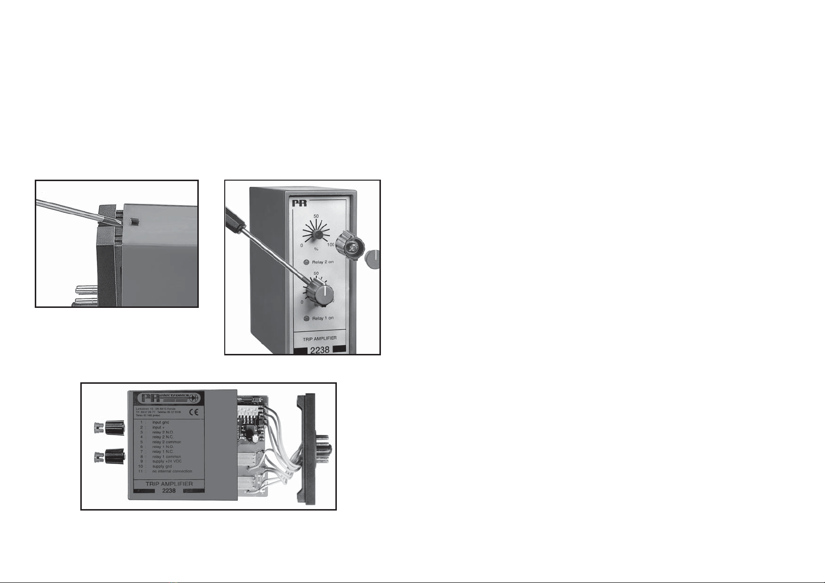
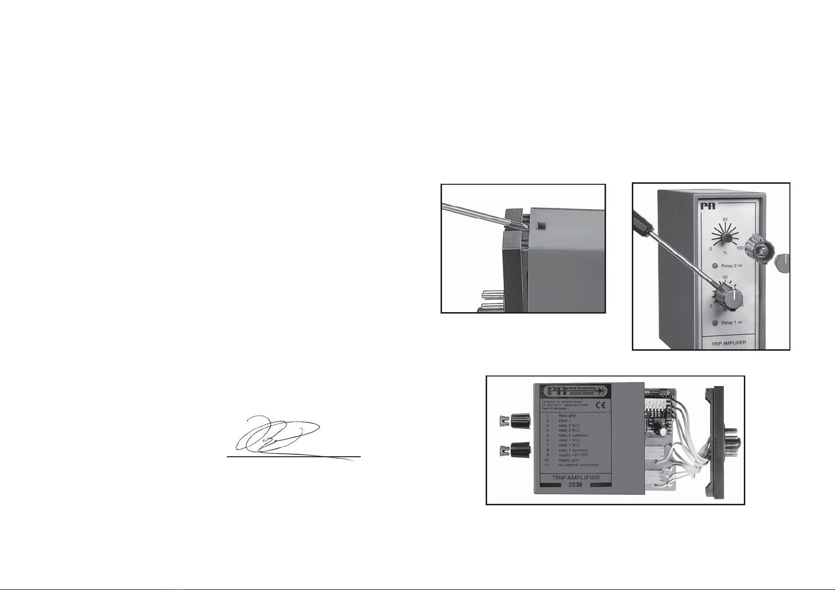
Modulets bagplade frigøres fra huset ved hjælp af en skruetrækker, som vist på
billede 1.
Inden printet kan udtages, kan det ved moduler med knapper være nødvendigt
at fjerne disse, se billede 2.
Derefter kan bagpladen udtrækkes sammen med printet, men vær opmærksom
på printets placering i huset, da det er muligt at isætte dette i flere positioner.
Træk ikke unødigt i ledningerne, men tag fat i printet, se billede 3.
Nu kan switche og jumpere ændres.
Det er vigtigt, at ingen ledninger kommer i klemme, når bagplade og huset
samles.
Billede 1: Adskillelse af bagplade og hus.
Billede 2: Afmontering af knapper.
Billede 3: Udtagelse af print for dipning og flytning af jumpere.

Belastningseffekt, (10%-max. belast) ........ < 1,5% / A
Strømbegrænsning (kortslutning)............... Typ. 2,2 A
Udgangsripple............................................ < 20 mVRMS
GOST R godkendelse:
VNIIM, Cert. No. ......................................... Se www.prelectronics.dk
Overholdte myndighedskrav: Standard:
EMC 2004/108/EF...................................... EN 61326-1
LVD 2006/95/EF ......................................... EN 61010-1
PELV/SELV.................................................. IEC 364-4-41 og EN 60742
9
UDGANG:
Udgangen er justerbar fra potentiometer i front i området 5...24 VDC. En grøn
lysdiode indikerer aktiv udgang. Kortslutningssikring begrænser strømmen til
typ. 2,2 Amp.
ELEKTRISKE SPECIFIKATIONER:
Specifikationsområde:
-20°C til +60°C
Fælles specifikationer:
Egetforbrug max......................................... 4 W
Isolation test / drift ..................................... 3,75 kVAC / 250 VAC
Transformator ............................................. EN 60742
Temperaturkoefficient................................. 0,05% / °C
Virkning af forsyningsspændings-
ændring (±10%).......................................... < ±30 mV
Transient stabilitet (10%-max. belast)........ < 250 mV
EMC-immunitetspåvirkning ....................... < ±0,5%
Relativ luftfugtighed ................................... < 95% RH (ikke kond.)
Mål (HxBxD) ............................................... 80,5 x 35,5 x 84,5 mm
Kapslingsklasse.......................................... IP50
Vægt........................................................... 425 g
Indgang:
Indgangsspænding..................................... 21,6...26,4 VAC
99...121 VAC
108...132 VAC
207...253 VAC
Frekvens..................................................... 50...60 Hz
Udgang:
Udgangsspænding..................................... 4,75...25,2 VDC
Udgangseffekt............................................ Max. 7 W
Udgangsstrøm............................................ 1 A / 5 VDC
0,55 A / 12 VDC
0,45 A / 15 VDC
0,3 A / 24 VDC
8

SWITCHMODE POWER SUPPLY
Type 2220
CONTENTS
Warnings . . . . . . . . . . . . . . . . . . . . . . . . . . . . . . . . . . . . . . 12
Safety instructions. . . . . . . . . . . . . . . . . . . . . . . . . . . . . . . 14
Declaration of Conformity . . . . . . . . . . . . . . . . . . . . . . . . . 16
How to dismantle SYSTEM 2200 . . . . . . . . . . . . . . . . . . . 17
Applications. . . . . . . . . . . . . . . . . . . . . . . . . . . . . . . . . . . . 18
Technical characteristics . . . . . . . . . . . . . . . . . . . . . . . . . . 18
Mounting . . . . . . . . . . . . . . . . . . . . . . . . . . . . . . . . . . . . . . 18
Input . . . . . . . . . . . . . . . . . . . . . . . . . . . . . . . . . . . . . . . . . 18
Output . . . . . . . . . . . . . . . . . . . . . . . . . . . . . . . . . . . . . . . . 19
Electrical specifications. . . . . . . . . . . . . . . . . . . . . . . . . . . 19
Order . . . . . . . . . . . . . . . . . . . . . . . . . . . . . . . . . . . . . . . . . 21
Block diagram . . . . . . . . . . . . . . . . . . . . . . . . . . . . . . . . . . 21
1110
BESTILLINGSSKEMA:
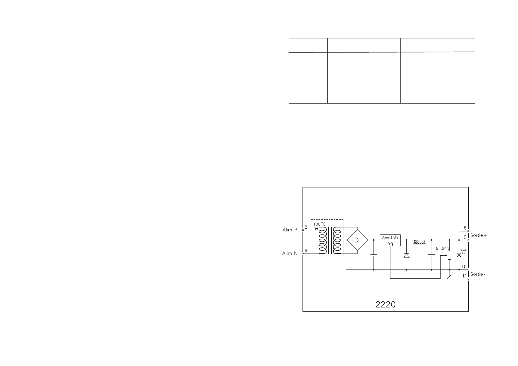
BLOKDIAGRAM:
Udgang
Type Version
2220 110 VAC : A
230 VAC : B
24 VAC : D
120 VAC : F
Speciel (5...24 V) : 0
24 VDC : 1
15 VDC : 2
12 VDC : 3
5 VDC : 4

1312
SYMBOL IDENTIFICATION
Triangle with an exclamation mark: Warning / demand.
Potentially lethal situations.
The CE mark proves the compliance of the module with
the requirements of the directives.
The double insulation symbol shows that the module is
protected by double or reinforced insulation.
WARNING!
This module is designed for connection to hazardous electric volt-
ages. Ignoring this warning can result in severe personal injury or
mechanical damage.
To avoid the risk of electric shock and fire, the safety instructions
of this manual must be observed and the guidelines followed.
The electrical specifications must not be exceeded, and the
module must only be applied as described in the following.
Prior to the commissioning of the module, this manual must be
examined carefully.
Only qualified personnel (technicians) should install this module.
If the equipment is used in a manner not specified by the
manufacturer, the protection provided by the equipment may
be impaired.
WARNING!
Until the module is fixed, do not connect hazardous voltages to
the module. The following operations should only be carried out
on a disconnected module and under ESD safe conditions:
Dismantlement of the module for setting of DIP-switches
and jumpers.
General mounting, connection and disconnection of wires.
Troubleshooting the module.
Repair of the module and replacement of circuit breakers
must be done by PR electronics A/S only.
WARNING!
To keep the safety distances, modules with two built-in relays
must not be connected to both hazardous and non-hazardous
voltages on the same module’s relay contacts.
SYSTEM 2200 must be mounted in socket type S3B Releco
(order no 7023).
GENERAL
HAZARD-
OUS
VOLTAGE
INSTAL-
LATION

The following apply to fixed hazardous voltages-connected modules:
The max. size of the protective fuse is 10 A and, together with a power switch, it
should be easily accessible and close to the module.
The power switch should be marked with a label telling it will switch off the
voltage to the module.
CALIBRATION AND ADJUSTMENT:
During calibration and adjustment, the measuring and connection of external
voltages must be carried out according to the specifications of this manual.
The technician must use tools and instruments that are safe to use.
NORMAL OPERATION:
Operators are only allowed to adjust and operate modules that are safely fixed in
panels, etc., thus avoiding the danger of personal injury and damage. This means
there is no electrical shock hazard, and the module is easily accessible.
CLEANING:
When disconnected, the module may be cleaned with a cloth moistened with
distilled water.
LIABILITY:
To the extent the instructions in this manual are not strictly observed, the
customer cannot advance a demand against PR electronics A/S that would
otherwise exist according to the concluded sales agreement.
1514
SAFETY INSTRUCTIONS
DEFINITIONS:
Hazardous voltages have been defined as the ranges: 75 to 1500 Volt DC, and
50 to 1000 Volt AC.
Technicians are qualified persons educated or trained to mount, operate, and
also troubleshoot technically correct and in accordance with safety regulations.
Operators, being familiar with the contents of this manual, adjust and operate the
knobs or potentiometers during normal operation.
RECEIPT AND UNPACKING:
Unpack the module without damaging it and make sure that the manual always
follows the module and is always available. The packing should always follow the
module until this has been permanently mounted.
Check at the receipt of the module whether the type corresponds to the one
ordered.
ENVIRONMENT:
Avoid direct sunlight, dust, high temperatures, mechanical vibrations and shock,
as well as rain and heavy moisture. If necessary, heating in excess of the stated
limits for ambient temperatures should be avoided by way of ventilation.
All modules fall under Installation Category II, Pollution Degree 1, and Insulation
Class II.
MOUNTING:
Only technicians who are familiar with the technical terms, warnings, and
instructions in the manual and who are able to follow these should connect the
module.
Should there be any doubt as to the correct handling of the module, please
contact your local distributor or, alternatively,
PR electronics A/S, Lerbakken 10, DK-8410 Rønde, Denmark,
tel: +45 86 37 26 77.
Mounting and connection of the module should comply with national legislation
for mounting of electric materials, i.a. wire cross section, protective fuse, and
location. Descriptions of Input / Output and supply connections are shown in the
block diagram and side label.
HOW TO DISMANTLE SYSTEM 2200
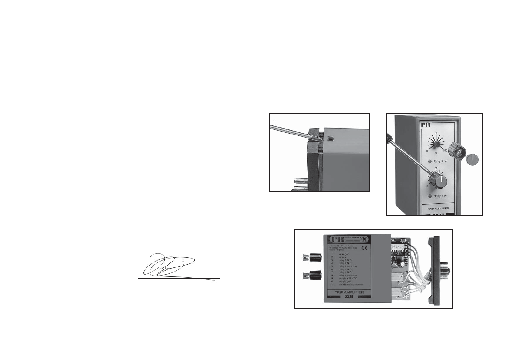
The back panel of the module is detached from the housing by way of a screw-
driver as shown in picture 1.
On a module with knobs, these may have to be removed before the PCB can be
taken out as shown in picture 2.
After this, the back panel can be pulled out together with the PCB, but please
notice the position of the PCB as there is a number of different positions in the
house. Do not pull the wires unnecessarily, instead pull the PCB, see picture 3.
Switches and jumpers can now be moved.
When assembling the back plate and housing, please make sure no wires are
stuck.
17
Picture 1: Dismantlement of back plate
and housing.
Picture 2: Removal of knobs.
Picture 3: Removal of PCBs for adjustment of DIP-switches
and replacement of jumpers.
DECLARATION OF CONFORMITY
As manufacturer
PR electronics A/S
Lerbakken 10
DK-8410 Rønde
hereby declares that the following product:
Type: 2220
Name: Switchmode power supply
is in conformity with the following directives and standards:
The EMC Directive 2004/108/EC and later amendments
EN 61326-1
For specification of the acceptable EMC performance level, refer to the
electrical specifications for the module.
The Low Voltage Directive 2006/95/EC and later amendments
EN 61010-1
The CE mark for compliance with the Low Voltage directive was affixed in the
year: 1997
Rønde, 7 October 2009 Kim Rasmussen
Manufacturer’s signature
16

OUTPUT:
The output is adjustable from front potentiometer in the range 5...24 VDC. A
green LED indicates active output. Short-circuit protection limits the current to
typ. 2.2 Amp. Output is isolated by 3.75 kVAC from input.
ELECTRICAL SPECIFICATIONS:
Specifications range:
-20°C to +60°C
Common specifications:
Internal consumption max.......................... 4 W
Isolation test / operation ............................ 3.75 kVAC / 250 VAC
Transformer ................................................ EN 60742
Temperature coefficient.............................. 0.05% / °C
Mains effect (±10%)................................... < ±30 mV
Transient stability (10%-max. load)............ < 250 mV
EMC immunity influence ............................ < ±0.5%
Relative air humidity................................... < 95% RH (non-cond.)
Dimensions (HxWxD).................................. 80.5 x 35.5 x 84.5 mm
Protection degree....................................... IP50
Weight ........................................................ 425 g
Input:
Input voltage............................................... 21.6...26.4 VAC
99...121 VAC
108...132 VAC
207...253 VAC
Frequency................................................... 50...60 Hz
Output:
Output voltage............................................ 4.75...25.2 VDC
Output power ............................................. Max. 7 W
Output current............................................ 1 A / 5 VDC
0.55 A / 12 VDC
0.45 A / 15 VDC
0.3 A / 24 VDC
19
SWITCHMODE
POWER SUPPLY
2220
• Mains voltage input
• Isolation 3.75 kVAC
• Adjustable output 5...24 VDC, max. 7 W
• Short-circuit protection
• Thermal overload protection
• Standard 11-pole relay socket
APPLICATIONS:
General power supply for smaller measurement systems requiring fixed stabilized
24 VDC, or supply for any other sensors, transmitters or as a general
variable power supply 5 to 24 VDC.
Two units may be connected in series for plus / minus or higher output voltage.
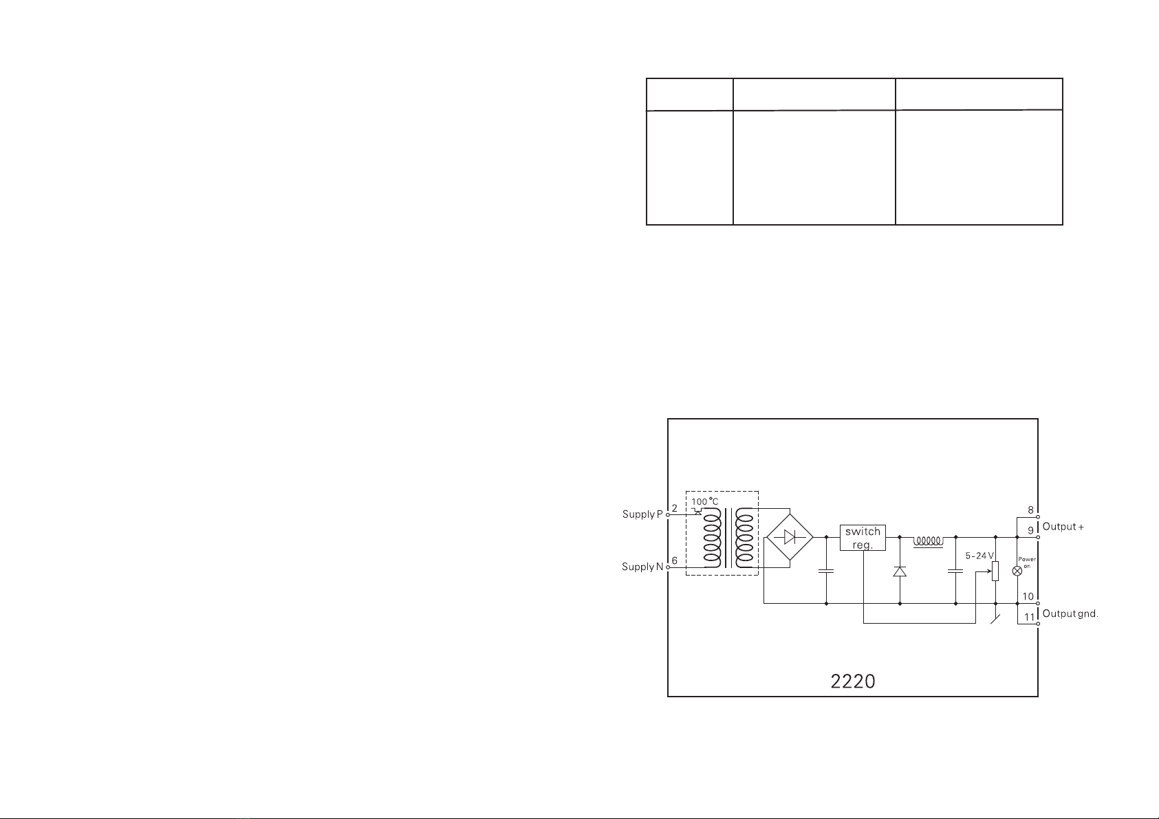
TECHNICAL CHARACTERISTICS:
The unit is based on secondary switchmode technology enabling an adjustable
output with a minimum loss of power. Isolation test voltage between input and
output is 3.75 kVAC. This makes the unit suitable for PELV/SELV applications. The
double-isolated safety transformer includes a 100°C thermal fuse which switches
off the input before the transformer is overheated. When the temperature returns
below 100°C the thermal fuse will automatically switch on the power supply.
MOUNTING:
The 2220 is for standard 11-pole socket mounting in all positions. To achieve
maximum cooling, vertical position and a small distance (10 mm) between
neighbouring units are recommended.
INPUT:
Standard supply voltages in accordance to the specifications. Galvanic isolation
is ensured by the double-isolated safety transformer.
18
21
Load effect, (10%-max. load) .................... < 1.5% / A
Current limit (short circuit).......................... Typ. 2.2 A
Output ripple .............................................. < 20 mVRMS
GOST R approval:
VNIIM, Cert. No. ......................................... See www.prelectronics.com
Observed authority requirements: Standard:
EMC 2004/108/EC ..................................... EN 61326-1
LVD 2006/95/EC......................................... EN 61010-1
PELV/SELV.................................................. IEC 364-4-41 and EN 60742
20
ORDER:
BLOCK DIAGRAM:
Output
Type Version
2220 110 VAC : A
230 VAC : B
24 VAC : D
120 VAC : F
Special (5...24 V) : 0
24 VDC : 1
15 VDC : 2
12 VDC : 3
5 VDC : 4

ALIMENTATION A DECOUPAGE
Type 2220
SOMMAIRE
Avertissements . . . . . . . . . . . . . . . . . . . . . . . . . . . . . . . . . 24
Consignes de sécurité. . . . . . . . . . . . . . . . . . . . . . . . . . . . 26
Déclaration de conformité. . . . . . . . . . . . . . . . . . . . . . . . . 28
Démontage du SYSTEME 2200 . . . . . . . . . . . . . . . . . . . . 29
Applications. . . . . . . . . . . . . . . . . . . . . . . . . . . . . . . . . . . . 30
Caractéristiques techniques . . . . . . . . . . . . . . . . . . . . . . . 30
Montage . . . . . . . . . . . . . . . . . . . . . . . . . . . . . . . . . . . . . . 30
Entrée . . . . . . . . . . . . . . . . . . . . . . . . . . . . . . . . . . . . . . . . 31
Sortie . . . . . . . . . . . . . . . . . . . . . . . . . . . . . . . . . . . . . . . . . 31
Spécifications électriques . . . . . . . . . . . . . . . . . . . . . . . . . 31
Référence de commande . . . . . . . . . . . . . . . . . . . . . . . . . 33
Schéma de principe . . . . . . . . . . . . . . . . . . . . . . . . . . . . . 33
2322
2524
SIGNIFICATION DES SYMBOLES
Triangle avec point d’exclamation : Attention ! Si vous ne
respectez pas les instructions, la situation pourrait être fatale.
Le signe CE indique que le module est conforme aux
exigences des directives.
Ce symbole indique que le module est protégé par une
isolation double ou renforcée.
AVERTISSEMENT !
Ce module est conçu pour supporter une connexion à des
tensions électriques dangereuses. Si vous ne tenez pas compte
de cet avertissement, cela peut causer des dommages corporels
ou des dégâts mécaniques.
Pour éviter les risques d’électrocution et d’incendie, conformez-
vous aux consignes de sécurité et suivez les instructions
mentionnées dans ce guide. Vous devez vous limiter aux
spécifications indiquées et respecter les instructions d’utilisation
de ce module, telles qu’elles sont décrites dans ce guide.
Il est nécessaire de lire ce guide attentivement avant de mettre
ce module en marche. L’installation de ce module est réservée à
un personnel qualifié (techniciens). Si la méthode d’utilisation de
l’équipement diffère de celle décrite par le fabricant, la protection
assurée par l’équipement risque d’être altérée.
AVERTISSEMENT !
Tant que le module n’est pas fixé, ne le mettez par sous tensions
dangereuses.
Les opérations suivantes doivent être effectuées avec le module
débranché et dans un environnement exempt de décharges
électrostatiques (ESD) : démontage du module pour régler
les commutateurs DIP et les cavaliers, montage général,
raccordement et débranchement de fils et recherche de pannes
sur le module.
Seule PR electronics SARL est autorisée à réparer le module
et à remplacer les disjoncteurs.
AVERTISSEMENT !
Afin de conserver les distances de sécurité, les modules à
deux relais intégrés ne doivent pas être mis sous tensions
dangereuses et non dangereuses sur les mêmes contacts du
relais du module.
Il convient de monter l’appareil SYSTEM 2200 sur un support du
type S3B Releco (numéro de référence 7023).
INFOR-
MATIONS
GENERALES
TENSION
DANGE-
REUSE
INSTAL-
LATION

Les connexions des alimentations et des entrées / sorties sont décrites dans le
schéma de principe et sur l’étiquette de la face latérale du module.
Les instructions suivantes s’appliquent aux modules fixes connectés en tensions
dangereuses :
Le fusible de protection doit être de 10 A au maximum. Ce dernier,
ainsi que l’interrupteur général, doivent être facilement accessibles et
à proximité du module. Il est recommandé de placer sur l’interupteur
général une étiquette indiquant que ce dernier mettra le module hors
tension.
ETALONNAGE ET REGLAGE
Lors des opérations d’étalonnage et de réglage, il convient d’effectuer les
mesures et les connexions des tensions externes en respectant les spécifications
mentionnées dans ce guide.
Les techniciens doivent utiliser des outils et des instruments pouvant être
manipulés en toute sécurité.
MANIPULATIONS ORDINAIRES
Les opérateurs sont uniquement autorisés à régler et faire fonctionner des
modules qui sont solidement fixés sur des platines des tableaux, ect., afin
d’écarter les risques de dommages corporels. Autrement dit, il ne doit exister
aucun danger d’électrocution et le module doit être facilement accessible.
MAINTENANCE ET ENTRETIEN
Une fois le module hors tension, prenez un chiffon humecté d’eau distillée pour
le nettoyer.
LIMITATION DE RESPONSABILITE
Dans la mesure où les instructions de ce guide ne sont pas strictement
respectées par le client, ce dernier n’est pas en droit de faire une réclamation
auprès de PR electronics SARL, même si cette dernière figure dans l’accord de
vente conclu.
27
CONSIGNES DE SECURITE
DEFINITIONS
Les gammes de tensions dangereuses sont les suivantes : de 75 à 1500 Vcc et de
50 à 1000 Vca. Les techniciens sont des personnes qualifiées qui sont capables
de monter et de faire fonctionner un appareil, et d’y rechercher les pannes, tout
en respectant les règles de sécurité. Les opérateurs, connaissant le contenu de
ce guide, règlent et actionnent les boutons ou les potentiomètres au cours des
manipulations ordinaires.
RECEPTION ET DEBALLAGE
Déballez le module sans l’endommager. Le guide doit toujours être disponible
et se trouver à proximité du module. De même, il est recommandé de conserver
l’emballage du module tant que ce dernier n’est pas définitivement monté. A la
réception du module, vérifiez que le type de module reçu correspond à celui que
vous avez commandé.
ENVIRONNEMENT
N’exposez pas votre module aux rayons directs du soleil et choisissez un endroit
à humidité modérée et à l’abri de la poussière, des températures élevées, des
chocs et des vibrations mécaniques et de la pluie. Le cas échéant, des systèmes
de ventilation permettent d’éviter qu’une pièce soit chauffée au-delà des limites
prescrites pour les températures ambiantes.
Tous les modules appartiennent à la catégorie d’installation Il, au degré de
pollution 1 et à la classe d’isolation Il.
MONTAGE
Il est conseillé de réserver le raccordement du module aux techniciens qui
connaissent les termes techniques, les avertissements et les instructions de ce
guide et qui sont capables d’appliquer ces dernières.
Si vous avez un doute quelconque quant à la manipulation du module, veuillez
contacter votre distributeur local. Vous pouvez également vous adresser à PR
electronics SARL, Zac du Chêne, Activillage, 4, allée des Sorbiers, F-69673
Bron Cedex (tél. : (0) 472 140 607) ou à PR electronics A/S, Lerbakken 10,
DK-8410 Rønde, Danemark (tél.:+45 86 37 26 77).
Le montage et le raccordement du module doivent être conformes à la
législation nationale en vigueur pour le montage de matériaux électriques, par
exemple, diamètres des fils, fusibles de protection et implantation des modules.
26
DEMONTAGE DU SYSTEME 2200
A l’aide d’un tournevis, dégagez la face arrière du module du boîtier (voir figure 1).
Sur un module équipé de boutons, il faut retirer ces derniers pour pouvoir extraire
la carte à circuits imprimés (voir figure 2).
Vous pouvez maintenant extraire la face arrière du module ainsi que la carte
à circuits imprimés. Veuillez repérer la position de cette carte car il existe de
nombreuses positions possibles dans le boîtier. Lorsque vous extrayez la carte à
circuits imprimés, tirez sur celle-ci et évitez de tirer sur les fils (voir figure 3).
Vous pouvez maintenant déplacer les commutateurs et les cavaliers. Lorsque
vous assemblez la face arrière du module et le boîtier, veuillez vérifier que les fils
ne sont pas coincés.
29
Figure 1 : Séparation de la face arrière
et du boîtier.
Figure 2 : Retrait des boutons.
Figure 3 : Extraction de la carte à circuits imprimès pour le
réglage des commutateurs et le remplacement des cavaliers.
DECLARATION DE CONFORMITE
En tant que fabricant
PR electronics A/S
Lerbakken 10
DK-8410 Rønde
déclare que le produit suivant :
Type : 2220
Nom : Alimentation à découpage
correspond aux directives et normes suivantes :
La directive CEM (EMC) 2004/108/CE et les modifications subséquentes
EN 61326-1
Pour une spécification du niveau de rendement acceptable CEM (EMC)
renvoyer aux spécifications électriques du module.
La directive basse tension 2006/95/CE et les modifications subséquentes
EN 61010-1
La marque CE pour conformité avec la directive basse tension a été apposée
en 1997
Rønde, le 7 october 2009 Kim Rasmussen
Signature du fabricant
28

SPECIFICATIONS ELECTRIQUES :
Plage des spécifications :
-20°C à +60°C
Spécifications communes :
Consommation interne............................... Max. 4 W
Tension d’isolation, test / opération........... 3,75 kVca / 250 Vca
Transformateur ........................................... EN 60742
Coefficient de température......................... 0,05% / °C
Effet d’une variation de la tension
d’alimentation (±10%) ................................ < ±30 mV
Stabilité transitoire (10% max.).................. < 250 mV
CEM (EMC) : Effet de l’immunité ............... < ±0,5%
Humidité relative......................................... < 95% HR (sans cond.)
Dimensions (HxLxP) ................................... 80,5 x 35,5 x 84,5 mm
Degré de protection ................................... IP50
Poids .......................................................... 425 g
Entrée :
Tension d’entrée ........................................ 21,6...26,4 Vca
99...121 Vca
108...132 Vca
207...253 Vca
Fréquence .................................................. 50...60 Hz
Sortie :
Tension de sortie ........................................ 4,75...25,2 Vcc
Puissance de sortie.................................... Max. 7 W
Courant de sortie ...................................... Max. 1 A / 5 Vcc
0,55 A / 12 Vcc
0,45 A / 15 Vcc
0,3 A / 24 Vcc
Effet de charge (10% max.) ....................... < 1,5% / A
Limite de courant (court-circuit)................. Typ. 2,2 A
Taux tension d’ondulation .......................... < 20 mVRMS
31
ALIMENTATION A DECOUPAGE 2220
• Entrée tension de réseau
• Isolation : 3,75 kVca
• Sortie réglable : de 5 à 24 Vcc, max. 7 W
• Protection contre les courts-circuits
• Protection thermique contre les surcharges
• Embase standard 11 pôles
APPLICATIONS :
Alimentation générale pour des systèmes de mesure simple fonctionnant avec
une tension stabilisée. La tension de sortie peut être réglée dans la gamme de
5 à 24 Vcc.
Le 2220 permet la connexion en série de 2 modules pour obtenir une alimentation
bipolaire ou pour obtenir une tension de sortie plus élevée.
CARACTERISTIQUES TECHNIQUES :
Le 2220 est basé sur la technologie du découpage secondaire assurant une
sortie réglable avec un rendement optimal.
La tension d’isolation de test entre l’entrée et la sortie est de 3,75 kVca. Ainsi, le
2220 est apte aux circuits PELV/SELV.
Le transformateur à double isolation assure une sécurité maximale et dispose
d’un fusible thermique qui protège le circuit d’entrée lorsque la température
interne dépasse 100°C. Le fusible est reactivé automatiquement.
MONTAGE :
Le 2220 utilise une embase standard 11 pôles et peut être monté dans toutes
les positions. Pour faciliter au mieux le refroidissement par convection naturelle,
la position verticale et un espace de 10 mm entre les modules avoisinants sont
recommandés.
ENTREE :
Alimentations standards selon les specifications. L’isolation galvanique est
assurée par le transformateur à double isolation.
SORTIE :
La sortie est réglable à l’aide d’un potentiomètre en face avant dans la gamme de
5...24 Vcc. Une LED verte indique que la sortie est active. Une protection contre
les court-circuits limite le courant à 2,2 A.
30
33
Approbation GOST R :
VNIIM, Cert. No. ......................................... Voir www.prelectronics.fr
Agréments et homologations : Standard :
CEM (EMC) 2004/108/CE .......................... EN 61326-1
DTB 2006/95/CE ........................................ EN 61010-1
PELV/SELV.................................................. IEC 364-4-41 et EN 60742
32
REFERENCE DE COMMANDE :
SCHEMA DE PRINCIPE :
Sortie
Type Version
2220 110 Vca : A
230 Vca : B
24 Vca : D
120 Vca : F
Spéciale (5...24 V) : 0
24 Vcc : 1
15 Vcc : 2
12 Vcc : 3
5 Vcc : 4

SCHALTMODUS
SPANNUNGSVERSORGUNG
TYP 2220
INHALTSVERZEICHNIS
Warnung . . . . . . . . . . . . . . . . . . . . . . . . . . . . . . . . . . . . . . 36
Sicherheitsregeln. . . . . . . . . . . . . . . . . . . . . . . . . . . . . . . . 38
Konformitätserklärung. . . . . . . . . . . . . . . . . . . . . . . . . . . . 40
Zerlegung des SYSTEMs 2200 . . . . . . . . . . . . . . . . . . . . . 31
Anwendung . . . . . . . . . . . . . . . . . . . . . . . . . . . . . . . . . . . . 42
Technische Merkmale . . . . . . . . . . . . . . . . . . . . . . . . . . . . 42
Montage . . . . . . . . . . . . . . . . . . . . . . . . . . . . . . . . . . . . . . 42
Eingang . . . . . . . . . . . . . . . . . . . . . . . . . . . . . . . . . . . . . . . 42
Ausgang . . . . . . . . . . . . . . . . . . . . . . . . . . . . . . . . . . . . . . 43
Elektrische Daten . . . . . . . . . . . . . . . . . . . . . . . . . . . . . . . 43
Bestellangaben . . . . . . . . . . . . . . . . . . . . . . . . . . . . . . . . . 45
Blockdiagramm . . . . . . . . . . . . . . . . . . . . . . . . . . . . . . . . . 45
3534
3736
ZEICHENERKLÄRUNGEN:
Dreieck mit Ausrufungszeichen: Warnung / Vorschrift.
Vorgänge, die zu lebensgefährlichen Situationen führen können.
Die CE-Marke ist das sichtbare Zeichen dafür, dass das
Modul die Vorschriften erfüllt.
Doppelte Isolierung ist das Symbol dafür, dass das Modul
besondere Anforderungen an die Isolierung erfüllt.
WARNUNG!
Dieses Modul ist für den Anschluss an lebensgefährliche elektri-
sche Spannungen gebaut. Missachtung dieser Warnung kann zu
schweren Verletzungen oder mechanischer Zerstörung führen.
Um eine Gefährdung durch Stromstöße oder Brand zu vermeiden
müssen die Sicherheitsregeln des Handbuches eingehalten, und
die Anweisungen befolgt werden.
Die Spezifikationswerte dürfen nicht überschritten werden, und
das Modul darf nur gemäß folgender Beschreibung benutzt wer-
den. Das Handbuch ist sorgfältig durchzulesen, ehe das Modul in
Gebrauch genommen wird. Nur qualifizierte Personen (Techniker)
dürfen dieses Modul installieren.
Wenn das Modul nicht wie in diesem Handbuch beschrieben
benutzt wird, werden die Schutzeinrichtungen des Moduls
beeinträchtigt.
WARNUNG!
Vor dem abgeschlossenen festen Einbau des Moduls darf
daran keine gefährliche Spannung angeschlossen werden, und
folgende Maßnahmen sollten nur in spannungslosem Zustand
des Moduls und unter ESD-sicheren Verhältnisse durchgeführt
werden:
Öffnen des Moduls zum Einstellen von Umschaltern und Über-
brückern.
Installation, Montage und Demontage von Leitungen.
Fehlersuche im Modul.
Reparaturen des Moduls und Austausch von Sicherungen
dürfen nur von PR electronics A/S vorgenommen werden.
WARNUNG!
Zur Einhaltung der Sicherheitsabstände dürfen Module mit zwei
eingebauten Relaiseinheiten nicht sowohl an gefährliche und
ungefährliche Spannung über die selben Relaiskontakte des
Moduls angeschlossen werden.
Das System 2200 wird in einen Sockel vom Typ S3B Releco
(Bestellnummer 7023) montiert.
ALLGE-
MEINES
GEFÄHR-
LICHE
SPANNUNG
INSTAL-
LATION
Other manuals for 2220
1
This manual suits for next models
1
Table of contents
Languages:
Other PR Power Supply manuals


Popular Power Supply manuals by other brands

patura
patura P 15 user manual

Delta Electronics
Delta Electronics DPS-300PB-1 Specifications

King Canada
King Canada Powerforce PX-500 instruction manual

WME
WME DPS404A user manual

Federal Signal Corporation
Federal Signal Corporation SelecTone PS250 Installation and maintenance instructions

Altronix
Altronix SMP7 installation instructions


