manuals.online logo
Brands
  1. Home
  2. •
  3. Brands
  4. •
  5. Cooper
  6. •
  7. Security Sensor
  8. •
  9. Cooper Scantronic 916 User manual

Cooper Scantronic 916 User manual

Lens Options
Creep Zone Wide Angle (standard)
Corridor Curtain Horizontal
Opening the Detector
1. Open screw covering, then loosen cover retaining screw
and release clip to remove cover.
The diagram shows the inside of the detector.
2. Remove the pcb range adjustment screw and remove pcb
assembly.
Description
The 916 Quad PIR is an indoor motion detector designed for
use in wired intruder alarm systems. White-light filters
minimise false alarms caused by intense white light (for
example car headlamps or direct sunlight). A fully sealed
pyro-chamber gives full protection against draughts and
insects. Interchangeable lenses make the 916 a highly
versatile detector.
The 916 also provides:
• Temperature Compensation
• Creep Zone
Specification
Voltage: 8 to 18VDC
Current: 5mA nominal (12mA walk test LED on),
25mA max.
Low voltage alarm: 7V nominal
Operating temp: -10 to +55 deg.C
Alarm period: 2 seconds
Control input: 12V
Lens: Standard 15m x 90 deg.
Additional Lens Kit - Part No. 301
Lens adjustment: 10 degrees vertical
White light filter: greater than 2000 Lux
RF Immunity: 20V/m
Specification subject to change without notice.
Quad Passive
Infra Red
Detector
Installation Guide
Manufactured in the UK by Scantronic Ltd.
Product Support (UK) - Tel: (0891) 616343 between 09:00 and 17:30,
Monday to Friday. (Calls charged at 50p per minute.) Product Support FAX
No. (01594) 544136
Pt. No. 496445 Issue b
Lens Kit Part No.301
25m
25m
25m
1.5m
2.4m
(max)
2.4m
(max)
2.4m
(max) 2.4m
(max)
Range at 4°
Range at 10°
Range at 10°
Range at 0°
Range at 0°
6m
15m
15m
15m
15m
12°
10°
Top Cable Entry Knockout
Mounting Screw Knockout
Alarm LED
Range Scale
Look Down Mirror/Pet Alley
Pyro
Terminals
Cable Restraint Tie Wrap
knockout
Main Cover Screw Boss
PCB Range adjustment screw
Insectproofgasket
Tamperswitch
Lower rear cable entry
knockout
Pushopenclips to release
lensretainingfunnel.
Removing Lens Assembly (Optional)
1. Press lens clamping clips to remove lens retaining frame
and remove lens.
2. Replace with new lens (observe orientation)
Scantronic
Leading the way in security
916
Walk and Control jumpers
Corniche mounting Corner mounting
Wall mounting
Positioning The Detector
When selecting a position for the PIR, observe the normal
precautions concerning the siting of Passive Infra-Red
detectors, for example:
Do not position the detector facing a window or direct
sunlight.
Do not site the detector immediately above or facing a
radiator or heat source.
Avoid strong air currents directly onto the detector.
If possible, avoid movement of animals in protected area.
To create a “Pet Alley”, swing down the mirror and set the
pcb range adjuster to 0º. Mount the detector at 1.6m high.
Mounting The Detector
1. Open the required cable and cable tie knockouts using a
small screw driver or pointed tool.
2. Mount the detector chassis in position.
3. Replace printed circuit board and fasten with the pcb
range adjustment screw.
IDIS Programming
You should program the detector before fitting it to the
chassis. Refer to “8136UK-50 Installation and Programming
Guide - IDIS Programming” for details.
When programming IDIS Detectors from an expander card
with three Prog pins then use the 3-way to 2-way Molex lead
and connect the flying red wire to the 12V terminator on the
Detector.
When programming IDIS detectors from an expander card
with two Prog pins then use a 2-way to 2-way Molex lead but
make sure you connect the 12V supply from the expander to
the 12V terminator on the detector.
Wiring
Walk Test Jumper
The Walk Test jumper at the bottom right hand corner of the
pcb controls the LED on the detector.
Remove the jumper to DISABLE the LED.
Put the jumper in the WLK position in order to use the LED for
walk tests or to use the Latch feature.
Replace the cover and carry on with testing.
Testing
Test the operation of the detector as follows:
1. Make sure the Walk jumper is in place.
2. Clear the protected area.
3. Either set the panel in ‘Day’mode OR
Set the panel in ‘Walk Test’ if you have connected the
walk test output to the detector.
4. Walk across the protected area from four random
directions. Walk at a rate of one normal step per second
within the detection pattern. The detector should alarm
within four steps in three out of four walk tests.
5. Stand outside the detection pattern and operate any
potential cause of false alarm (for example, switch lights
on and off, open and close doors). If the unit detects a
deliberate false alarm, try adjusting the detector pattern.
6. Stand outside the detection pattern and observe the
detector’s operation for three to five minutes. The detector
should not alarm. If so, locate and correct the cause.
Adjusting Coverage
1. Remove the cover.
2. Loosen pcb range adjustment screw and slide the pcb up
or down to give the required coverage. Note the range
scale on the edge of the pcb. “Lens Options” shows the
ranges obtainable at various settings on the range scale.
3. Tighten the pcb range adjustment screw to fix the pcb in
place, and replace the cover.
Masking
On some installations it may be impossible to position a
detector to avoid a problem area (for example , a pilot light in a
kitchen). In that case mask the lens segment covering the
problem area. Fit a piece of the masking material supplied on
the inside of the lens behind the affected segment
Maintenance
There are no user serviceable parts inside the detector. Every
six months remove dust from the detector lens by wiping
gently with a clean dry cloth.
Service
Return any unit malfunctioning or in need of repair, to the
place of purchase or national supplier. Include your company
name, address and a description of the problem.
3 12V
40V
5 Sig
IDIS Expander Card
12V
0V
Sig

Other Cooper Security Sensor manuals

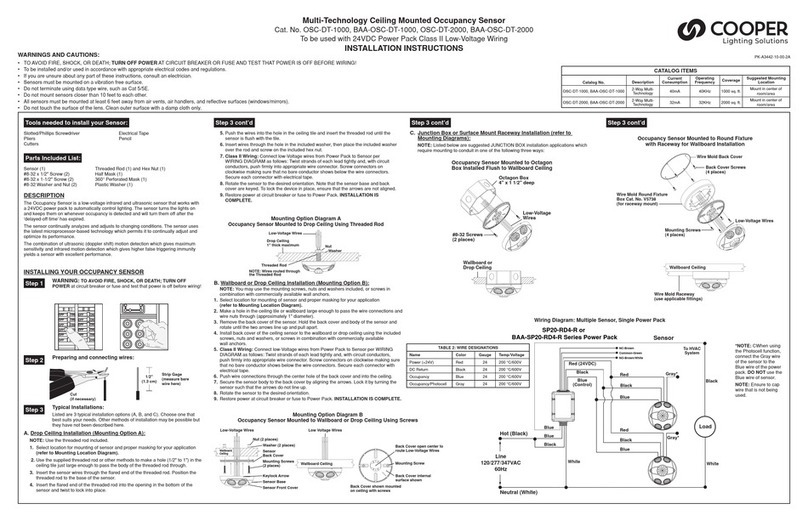
Cooper OSC-DT-1000 User manual

Cooper

Cooper OSC-DT-1000 User manual

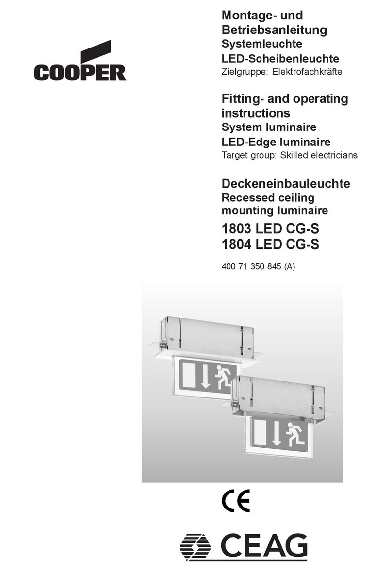
Cooper 1803 LED CG-S Manual

Cooper

Cooper 1803 LED CG-S Manual

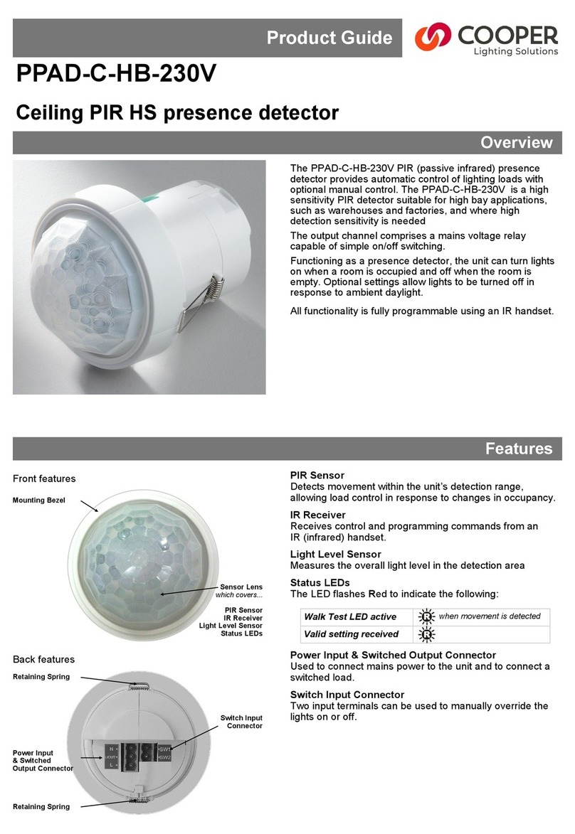
Cooper PPAD-C-HB-230V User manual

Cooper

Cooper PPAD-C-HB-230V User manual

Cooper 29021 LED CG-S Manual

Cooper

Cooper 29021 LED CG-S Manual

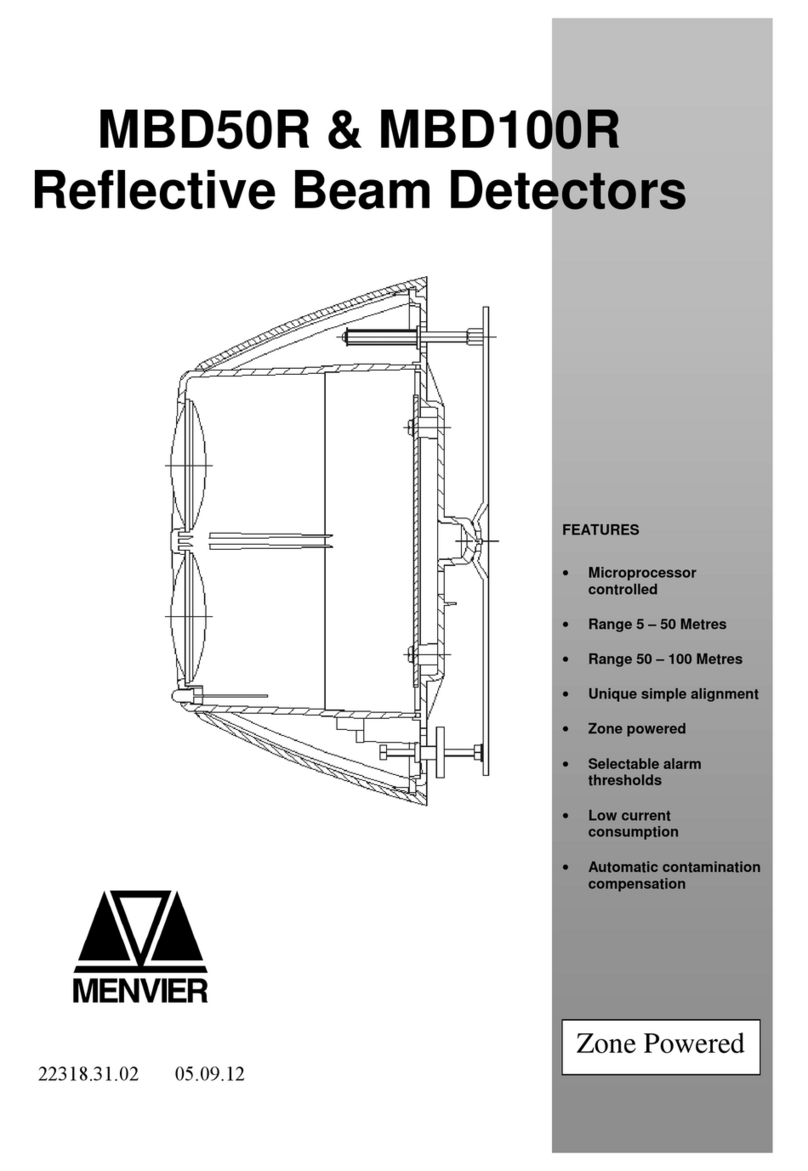
Cooper MBD50R User manual

Cooper

Cooper MBD50R User manual

Popular Security Sensor manuals by other brands

Vertiv GEIST RTAFHD3 Quick installation manual

Vertiv

Vertiv GEIST RTAFHD3 Quick installation manual

GE 868 GEN2 installation instructions

GE

GE 868 GEN2 installation instructions

Lechange WP1 Series quick start guide

Lechange

Lechange WP1 Series quick start guide

Satel AOCD-260 manual

Satel

Satel AOCD-260 manual

JOB detectomat HDv 300X TS Operation and installation manual

JOB

JOB detectomat HDv 300X TS Operation and installation manual

REED R9200 instruction manual

REED

REED R9200 instruction manual

Siemens OOH740-A9-Ex Technical manual

Siemens

Siemens OOH740-A9-Ex Technical manual

Bosch Security PC1A installation guide

Bosch Security

Bosch Security PC1A installation guide

Watts BLK01 RF installation manual

Watts

Watts BLK01 RF installation manual

DSC PG4914 installation instructions

DSC

DSC PG4914 installation instructions

CARLO GAVAZZI Guardian 2 Original user manual

CARLO GAVAZZI

CARLO GAVAZZI Guardian 2 Original user manual

LST B524IEFT-1 Specification sheet

LST

LST B524IEFT-1 Specification sheet

Enginko EGK-LW22CCM operating manual

Enginko

Enginko EGK-LW22CCM operating manual

SENTRONIC VS133-P user guide

SENTRONIC

SENTRONIC VS133-P user guide

Bosch AP1-P installation instructions

Bosch

Bosch AP1-P installation instructions

SGB VL 330 Installation advice

SGB

SGB VL 330 Installation advice

LEGRAND 675 29 quick start guide

LEGRAND

LEGRAND 675 29 quick start guide

ZUDSEC ZDD-285PIR installation guide

ZUDSEC

ZUDSEC ZDD-285PIR installation guide

manuals.online logo
manuals.online logoBrands
  • About & Mission
  • Contact us
  • Privacy Policy
  • Terms and Conditions

Copyright 2025 Manuals.Online. All Rights Reserved.