COP-USA AU40MZ User manual

1
Intelligent Control Keyboard
Manual Operation
Please read the operation manual carefully before using

2
SAFETY PRECAUTIONS
CAUTION
RI SK OF ELECTRI C
SHOCK. DO NOT OPEN!
CAUTION:
TO REDUCE THE RI SK OF ELECTRI CAL SHOCK, DO DOT
OPEN COVERS. NO USER SERVICEABLE PARTS INSI DE.
REFER SERVI CI NG TO QUALI FI ED SERVI CE PERSONNEL
The l i ght i ng f l ash wi t h a ar rowhead symbol, in an
equilateral triangle, is intended to alert the user.
There i s uni nsul ated “ dangerous vol tage” presence
near by the product ' s encl osure whi ch may be risk of
to persons .
The excl amation point within an equilateral
triangle is intended to alert the user to reference
of t he i mport ant operati ng and mai ntenance
(servicing) instructions .
THE PRODUCT CODE MARKED ON THE BOTTOM COVER. PLEASE
FILL THE CODE IN THE FOLLOWING BLANK. PLEASE SAVING
THIS SPECIFICATION CAREFULLY, SOTHAT CHECKING.
MODEL: ________________________
PRODUCT CODE:________________________
V2.1

3
Contents
Notes for Attention………………………………………………………………4
Ⅰ、The first chapter Panel and functions ……………………………………….6
1.1 Front Panel…………………………………………………………………...6
1.2 back Panel……………………………………………………………………7
1.3 Technical Parameter………………………………………………………….8
、The second chapter Operation Specification………………………………….9
2.1 Please keep all the packing documents……………………………………………9
2.2 Dimension……………………………………………………………………9
2.3 Exterior connecting introduction………………………………………………9
2.4 Display after power on………………………………………………………...10
2.5 Keyboard Operation …………………………………………………………10
2.6 The operation of keyboard menu……………………………………………….13
AppendixⅠ:Troubleshooting ………………………………………………..16
AppendixⅡ:Maintenance service terms ……………………………………..17

4
Notes for Attention:
This manual is to help you use the product correctly, before using for the first time,
make sure read the manual carefully, the safe information and other attentions in
terms mentioned will help you use this products well.
¾Electric safe
Observe all national and area electric safety standards in application. Adopt
DC12V/1.0A power supply, input rated voltage is marked in relative space, If the
power supply and voltage can’t be sure in installation place, please contact with
distributor or factory.
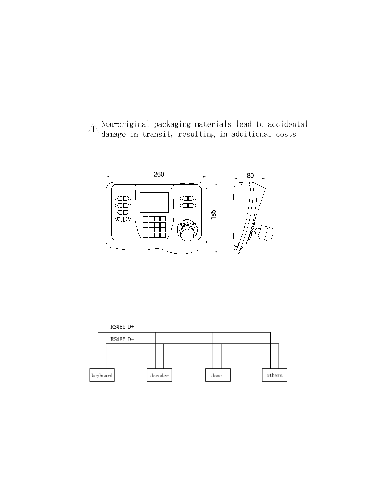
¾Transport carefully
Avoid incorrect operation methods such as heavy pressing, strong vibration, dip in,
etc. during the course of transportation, store and installation otherwise the product
could be damaged. There are sophisticated optical and electronic components inside
the product. Please do not dismount components inside the product to avoid
occurrence of trouble. Whether delivery or return for repair, if there is no part inside
the product, then needs repair by customer himself.
¾The competency requirement on maintenance person
The installation, maintenance about the device should be installed by the qualified
maintenance technologic person. When the device has problem, find the problem
according to spec first instead of maintaining it in a hurry, find the professional
maintenance person if can’t find the reason. About the maintenance, should be
carry out by the authorized maintenance person.
¾Installation request
zDon’t storage, install and use the product in inflammable, explosive dangerous
eare.
zDo not apply the product under the state exceeding limited temperature,
humidity or specifications of power supply.
zFor open or dismantle panel, maybe cause electric shock, don’t try to repair by
yourself, please contact us about all maintenance.
zPlease pull out the power supply, before clear such product. Do not use the
liquid or spray cleaner. Please don’t brush by wet cloth to avoid scratch and
corrosive liquid be into the machine which cause danger.
zContact us if followings appear:

5
a. Lines of power supply and control are broken
b. Using the wrong power supply type or voltage
c.fallorcoverisbroken
d. Capability in Products is abnormal
e. Doesn’t work if according to manual
The whole machine can be kept repair for 3 years
(Remark: LCD screen savers repair for one year)

6
Ⅰ、The first chapter Panel and functions
Such Keyboard is a product supporting with Intelligence Dome Camera,
decoder and other terminal receivers. It connects to the receiver by EIA/RS-485
electric interface. Without the bus driver, one keyboard at most to control 32 domes
or decoders, and the longest communication distance is 1.2Km. the intelligence
dome camera can be controlled and setup expediently by such control keyboard, and
it can also control the terminal decoder directly, achieve the control to the Pan/Tilt,
lens, light, wiper and other front equipments.
1.1 Front Panel
Smart appearance, LCD screen, key-press area, 3-Axis joystick compose the
front panel; Among, LCD Screen is used to display system state and operation
information;3-Axis is mainly used to up and down, left and right of P/T or Dome
control shift gears, far and near of focus lens.
②
③
①
Picture 1
①LCD Screen ②Joystick ③Function Area
Press-key:
Type Name Remark
①LCD screen Display system state and operation information
②Joystick
Assistant menu and key-press operation,
including control up and down, left and right of
P/T or Dome control shift gears, far and near of
focus lens.
③function key-press see keyboard key-press operation

7
1.2 Back Panel
Picture 2
①Power interface ②Brightness of LDC screen adjustable press
③Power、communication interface ④Video interface
S.N. Name Mark Remark
1 Power interface
POWER Connect to exterior steady power supply input
DC12V/1A DC voltage from the interface,
standard power adapter can be used directly.
2
Brightness
adjustment
button
Brightness adjustment button
3
Communication
interface
RS485+
RS485 Communication interface
RS485-
RS485+
RS485 Communication interface
RS485-
DC12V
Power supply DC12V/1A
GND
4 Video interface
VIDEO OUT one video output
VIDEO IN four video input

8
1.3 Technical Parameter
Communication Integrate 16 protocols ,band rate from 2400bps 、
4800bps、9600bps、19200 bps adjustable.
Control RS-485,can control many front end equipments such as
dome, decoder, intelligent P/T, etc. directly.
Joystick control 3-Axis shift joystick, control P/T, lens.
Menu function OSD menu function
Screen display LCD
Communication distance Max to 1200 meters
Power supply DC12V/1A
Dimension 260mm×185mm×80mm

9
、The second chapter Operation Specification
2.1 Please keep all the packing documents
Please keep the original packing documents after opening the packing in order
to packing the keyboards to send to the agent or factory to deal with if problems
have.
2.2 Dimensions
Picture 3
2.3 Exterior connecting introduction
When connecting with other equipments, can’t be connected crossed, must
connect with the corresponding pole.
Picture 4

10
2.4 Display after power on
When the keyboard is powered on, there will be displayed the address of current dome,
baud rate, protocol code and version code, such information will be displayed for 10
seconds. If the user has known the information, can operate the keyboard directly,
such information will be disappeared automatically. If there are displaying the
information as follows:
It means the current address is 001, the baud rate is 2400bps, the protocol code is
P003(the corresponding relations of the protocol code with the protocol will be listed
in Table 2),the version code is V1.0 After 10 seconds, it will be displayed to keyboard
operation interface, the content of input data buffer ,and the current address will be
displayed at the furthest bottom of the screen. As the following picture, the input data
is 0000, the current address is 001.
Please setup the address,protocol,baudrate as the same with
the dome;Otherwise it would cause the failure communication
to be out of control of the PTZ.
2.5 Keyboard operation
¾modify the dome camera address CAM
zpress number: “1-1024”
zpress key: CAM
After modify, the area of current address will display the address inputted
¾setup the preset position: PRESET
zpress number: “1-128”
zpress: PRESET
¾call preset position CALL

11
zpress number: “1-128”
zpress: CALL
¾Delete presets CLEAR
zpress clearandnumber
zpress PRESET
¾start up tracking
zpress number: “1-6”
zpress: SHOT
¾setup the left point of the line scanning
zpress: AUTO
zpress: ON
¾setup the right point of the line scanning
zpress: AUTO
zpress: OFF
¾running the line scanning
zPress Number
zPress AUTO
Explain: some protocols do not need to setup the line scanning, just run the line
scanning directly. After running, if the dome or Pan/Tilt is out of control,
probably the protocol adopted doses not support line scanning
¾Replay self-study
zPress: number
zPress: PATTERN
¾Record self-study
zPress PATTERNandNumber
zPress ON
¾Stop record self-study
zPress PATTERNandNumber
zPress OFF
¾Open keyboard menu
zPress MENU
¾Open dome or P/T menu
zPress for 2 seconds MENU
¾Video input select
zPress 1-4

12
zPress VIDEO
¾Lens Control
zFarzoom WIDE Nearzoom TELE
zFarfocus FAR Nearfocus NEAR
zBigiris OPEN Smalliris CLOSE
¾Assistant Function
zPress FUNC, key in number“0-10” Corresponding functions of different
numbers refer to table -1
zPress ON
Table 1(if the function is out of control, probably such protocol is not support
such operation)
NUM CONTROL OBJECT KEYBOARD OPERATION
FUNC+N+ON FUNC+N+OFF
1 Backlight Compensation On Off
2 Low LUX(D/N switch)Force On Auto switch
3 Menu/Screen On Off
4 Digital Magnification On Off
5 Reserve Reserve Reserve
6 FOCUS Auto Manual
7 IRIS Auto Manual
8
White Balance
Auto Manual
9 Indoor Mode Outdoor Mode
10 ATW Single lock
91-98 PELCO Assistant operation
AUX1—8 On Off
¾control of the dome / Pan/Tilt
Move the joystick until the camera reaches desired position. To reach the fastest
spin of camera, move the joystick utmost from center. Twist the joystick
clockwise to zoom in and counterclockwise to zoom out.
2.6 The operation of keyboard menu

13
Press MENU to enter menu press and again to exit menu. After enter the menu,
move the joystick up or down to move the cursor up or down; move
the joystick left or right to adjust the content of current menu.
2.6.1 MAIN MENU at “PROTOCOL SETTING” item, move the
joystick to right, display the submenu “PROTOCOL SETTING”.
Move the joystick up or down to choose the menu item, and move
the joystick right or left to setup the parameter.
¾PROTOCOL At such item, move the joystick right or left to
display:P000—P001—P002—P003—P004—P005—P006—P0
07—P008—P009—P010—P011—P012—P013—P014—P015
16 kinds of protocols. The corresponding of the protocol code
andprotocolnameasfollowing:
Table2
CODE NAME
P000 A01
P001 B01
P002 SANTACHI
P003 PELCO-D
P004 PELCO-P
P005 PANASONIC
P006 LONGCOMITY
P007 HD600
P008 LILIN
P009 VICON
P010 MOLYNX
P011 KALATE
P012 VCL
P013 RESERVED
P014 ALEC
P015 ULTRAK
¾BAUD RATE At such item, move the joystick right or left to choice the four
baud rates: 2400bps—4800bps—9600bps—19200bps
PROTOCOL SETTI NG
1. PROTOCOL
2.BAUDRATE 9600
3. BACK
P001
MAI N MENU
1. PROTOCOL SETTI NG
2.CAMERA SETTING
3.PROGROM
4.VIDEO CH
1
5.OSD ON
6.EXIT

14
¾BACK At such item, move the joystick right or left to display
the submenu (MAIN MENU)
2.6.2 CAMERA SETTUP At the main menu item “CAMERA
SETTUP”, move the joystick right to display the submenu
“CAMERA SETTUP”. Move the joystick up or down to choice the
menu item and move the joystick right or left to setup the parameter.
¾BACK LIGHT moves the joystick at such item right or left to
switch the back light ON/OFF.
¾ICR SHOT move the joystick at such item right or left to switch the ICR SHOT
ON-AUTO.
¾IRIS move the joystick at such item right or left to switch the IRIS
AUTO-MANUAL.
¾D-ZOOM move the joystick at such item right or left to switch the Digital
ZOOM ON-OFF.
¾FOCUS move the joystick at such item right or left to switch the FOCUS
AUTO-MANUAL
¾WB move the joystick at such item right or left to switch the WHITE BALANCE
SET among AUTO—MANUAL—OUTDOOR—INDOOR—ATW—ONEPUSH.
¾OSD OF CAM move the joystick at such item right or left to switch the menu
or screen ON/OFF.
¾BACK move the joystick at such item right or left to return MAIN MENU
2.6.3 PROGRAM At the main menu item “PROGRAM”, move the joystick right to
display the submenu “PROGRAM”. Move the joystick up or down to choice the
menu item, and move the joystick right or left to setup the parameter.
¾SET AP START POT move the joystick at such item right or
left to set the current position of Pan/Tilt or dome as the start
point of the line scanning.
¾SET AP END POT move the joystick at such item right or left
to set the current position of Pan/Tilt or dome as the start point of
the line scanning.
¾RUN AP move the joystick at such item right or left to run the
line scanning from the start point to the end point.
¾SET PATROL move the joystick at such item right or left to change the tracking
number among 01-06. To press OPEN to enter the submenus of tracking edit. At
CAMERA SETTING
1.BACK LIGHT
2.ICRSHOT
3. D- ZOOM
4. IRIS
5. FOCUS
6. WB
7. OSD OF CAM
8. BACK
PROGROM
1. SET AP START POT
2.SET AP END POT
3. RUN AP
4. SET PATROL
5. RUN PATROL
6. SET PATTERN
7. RUN PATTERN
8. BACK

15
such submenu, move the joystick right or left to move the active cursor right or
left, and move the joystick up or down to add or reduce the content of current
menu item. SEQ:XX(XX is the current editing tracking number), after edit the
tracking, press CLOSE to exit and save the current setup.
¾RUN PATROL move the joystick at such item right or left to change the tracking
number among 01- 06. And press OPEN to run the tracking.
¾SET PATTERN Set tracking self study。
¾RUN PATTERN move the joystick at such item right or left to run PATTERN.
¾BACK move the joystick at such item right or left to return the MAIN MENU.
2.6.4 VIDEO Picture channel selection.1-4 can be selected。
2.6.5 OSD character display ON-open/OFF-close。
2.6.6 EXIT Quit Menu。
AppendixⅠTroubleshooting

16
Problem REASONS
PROBABLY Possible Solution
No Video No power supply
1.Check the connection of power
line
2.If the power supply is DC12V
Can not control the
appoint dome or Pan/Tilt
1.Incorrect protocol
2.Incorrect baud rate
3.Incorrect address
1.The protocol is same between
keyboard and dome or Pan/Tilt?
2.The baud rate is the same between
keyboard and dome or Pan/Tilt?
NOTE: The above lists some common causes problems, as well as solutions for
reference purposes only. If you encounter other specific problems, you can consult
directly with dealers, the request for technical support.

17
AppendixⅡ: Maintenance service terms
1、Service range
In one year the cargo sold, the problem is approved caused by product material
or techniques defect, manufacturer will repair or replace for free;
Warranty period of all parts which have repaired or replaced is 90 days after
sending out cargoes;
Products can’t be repaired for free for manpower cannot dispute reason(such as
war, earthquake, lightning strike),improper use, deviant operation, revise, normal
fray or problem caused by accident;
Factory takes on no responsibility on p damage and loss caused by product
special use or application. The compensation on fell back, neglect or infringement
about products will not over products value. Manufacturer won’t take on any
responsibility on special, sudden or continued damage caused by any other
reason;
Trouble products over warranty period, we do repay maintenance service lifetime.
whole machine is repaired for free for 3 years( remark: camera module for 1 year)
2、Repair for free terms
Cargoes need repair during repair for free period, buyer connect manufacturer to get
RAN, and provide product information below along with cargoes;
Type and serial NO.;
Delivery date, order NO., sale order NO. or manufacturer invoice;
Detailed problem phenomenon
If having disputes on repair for free terms hereinbefore, please attach written
explanations when returning products.
3、Return
For returning cargoes quickly, please contact manufacturer to get RAN( repair NO.),
then arrange sending cargoes to manufacturer. All returned cargoes should mark RAN
clearly. Delivery way of returning cargoes is the same as way of delivery to
manufacturer. Manufacturer only undertake the single freight of manufacturer send
cargo to customer after repair.
Model and parameters are subject to change without notice.
Table of contents
Other COP-USA Keyboard manuals