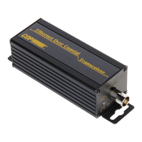
COP EA-EOU101K User manual

1
Ethernet Over UTP Master/Slave Transceiver
MODEL: EA-EOU101K
◆ Description:
EA-EOU101 is designed to extend IP Ethernet transmission and use UTP cable to IP cameras
or devices. EA-EOU101 transmission distance up to 1000m (3300ft), these transceivers are
extremely simple to use. Status LEDs indicate power and link connectivity/activity for RJ45 ports.
◆ Feature:
No PC required, plug & play and reducing the cables cost
Transmit IP camera or other 10/100 Base-T full duplex IP devices over CAT-5e cable
Up to 1000 meter transmission distance by CAT-5e cable
Built-in 6KV surge protection at BNC and 4KV at RJ45 ports
Multi EoU transceiver/IP cameras to one transceiver at NVR side transmission
◆ SPECIFICATIONS:
MODEL EA-EOU101
Extender Interface
Connector Type
1 x BNC with BNC to Terminal Block Adaptor [15-BT104]
Cable Type The Straight through cable Cat.5e/Cat.6
Max. Transmission Distance 1000m (3300ft.) for the Cat.5e cable
Ethernet Interface
Connector Type
1x RJ-45 with LEDs on Connector
Cable Type Straight through or cross-over Cat5 Cable, Auto MDI/MDIX
Rate IEEE 802.3x, Auto-Detection for 10/100Base-T and full/half
duplex
Control & Indicators
Color LED
UTP Data Signal Strength
Green:GOOD (Link speed > 60 Mbps)
Amber:MEDIUM (Link speed 20~60Mbps)
Red:BAD (Link speed < 20Mbps)
OFF:NO LINK
Yellow LED (On RJ45) Power On
Green LED (On RJ45) Link/Act.
Push Button
Reset / Pairing(1) (Join or Leave Network Group(2))
Push
Duration
LED
Status
Description
1 – 3 sec Red Blinking Join/Host New
Network Group(3)
5 – 8 sec Amber Blink
Once -> OFF
Leave Current Network
Group(4)
12 - 30 sec OFF -> Amber
Blink Once
Reset to Default Network
Group
Power
Input Operating Voltage DC 12V / 500mA
Power Consumption 1.5W

2
Mechanical & Environmental
Weight 175g (6.17 oz)
Dimensions (W × L × H) 38 x120 x 33mm (1.5”x4.7”x1.3”)
Operation Temperature -20°C ~ +60°C (-4°F ~ 140°F)
Storage Temperature -30C ~ 80C (-22°F ~ 176°F)
Humidity 20% to 85% RH. (non-condensing)
1. All EA-EOC101 factory default is paired to same network group, it can be installed directly, no
need pairing again.
2. The transmission system consists of one EA-EOC101 transceiver at NVR side and up to four
EA-EOC101 transceivers that connect to IP cameras or other IP device.
3. Use two or more transmission systems at NVR side, and there are crosstalk problems on cables
that between different transmissions systems, otherwise no need to do pairing process.
4. To join another network group, must leave current group first, then do the group join.
◆ Packing
1. EA-EOC101 Transceiver ×2
2. BNC to Terminal Block Adaptor [15-BT104] ×2
3. User manual ×1
4. Wall Mount Kit ×2
5. Power Adaptor ×2 [Option: DC 12V / 500mA]
◆ PANEL DESCRIPTIONS:
1. DC12V IN: Power Supply DC12V/500mA.
2. ETHERNET: Ethernet Interface (10/100Mbps for full duplexer)
3. ACT./LINK: Data Link for indication LED
4. POWER: Power On for indication LED
5. SIGNAL STRENGTH: G(Green):GOOD
A(Amber):MEDIUM
R(Red):BAD
OFF:NO LINK

3
6. COAX DATA: Plus BNC Adapter can UTP Transmission
7. PAIRING/RESET: PAIRING for network group join/leave, RESET for factory default network
group
8. BNC Adapter: BNC to Terminal Block adaptor [COP PN: 15-BT104]
◆ CONNECTION DIAGRAM:
Notice: The cable quality, camera bandwidth requested and supply power noise
will caused the distance which may not match as bellowi specification.
◆Application Diagram 1: Single Camera EoU Transmission System
◆Application Diagram 2: Star Two Cameras EoU Transmission System
◆Application Diagram 3: Star Three Cameras EoU Transmission System

4
◆Application Diagram 4: Star Quadruple Cameras EoU Transmission System
◆Application Diagram 5: Daisy-Chained Quadruple Cameras EoU Transmission System

5
Before do the pairing process, please check as bellow notice
1) If only setup one transmission system at NVR or control room side, no need to do pairing
process.
2) When using two or more transmission systems at NVR or control room side, if there are no
cross-talk problems between different transmission systems, no need to do pairing
process.
EoC/EoU Transmission System Network Group Pairing Instructions
Step 1: Setup EoC/EoU Transmission System
Connect all the coaxial, cat. 5e cables between transceivers, setup cameras and NVR then
power supplied to the system that one of the application diagrams.
Step 2: Host/Master Side Leaving Current Network Group
On transceiver at NVR side, using the straightened paper-clip to
access the small push button for 5 ~ 8 seconds, the color LED will
begin AMBER blinking once then OFF.
Step 3: Host/Master Side Create an New Network Group
On transceiver at NVR side, using the straightened paper-clip to access the small push
button for 1 ~ 3 seconds, the color LED will begin RED blinking.
Step 4: Slave Side Transceiver Leaving Current Network Group
On transceiver at Remote side (close to IP camera/device), using the straightened paper-clip
to access the small push button for 5 ~ 8 seconds, the color LED will begin AMBER blinking
once then OFF.
Step 5: Slave Side Transceiver Joining New Network Group
EOC/EOU transceivers at Remote side (close to IP camera/device), using the straightened
paper-clip to access the small push button for 1 ~ 3 seconds, the color LED will begin RED
blinking. The transceivers will find each other and starting the transmission.
Step 6: Adding Additional Transceiver Joining New Network Group
Repeat Step 4 and 5 to adding additional transceiver to new network group.
In Pairing Process Notice
1) In joining or leaving process, if you are not sure that joining or leaving has been
successful, you can RESET the transceiver (press the push button 12 to 30 seconds) ,
and repeat above steps.
2) After re-apply power or RESET transceiver, please wait color LED Amber blinking once
then GREEN, its means power on reset finished and you can do the pairing process.
3) The transceiver is from LEAVE to JOIN state (color LED RED blinking), it must join new
network group in 2 minutes, otherwise it will become LEAVE state again.
VER:2170412
Table of contents
Other COP Transceiver manuals