5
Before do the pairing process, please check as bellow notice
1) If only setup one transmission system at NVR or control room side, no need to do pairing
process.
2) When using two or more transmission systems at NVR or control room side, if there are no
cross-talk problems between different transmission systems, no need to do pairing
process.
EoC/EoU Transmission System Network Group Pairing Instructions
Step 1: Setup EoC/EoU Transmission System
Connect all the coaxial, cat. 5e cables between transceivers, setup cameras and NVR then
power supplied to the system that one of the application diagrams.
Step 2: Host/Master Side Leaving Current Network Group
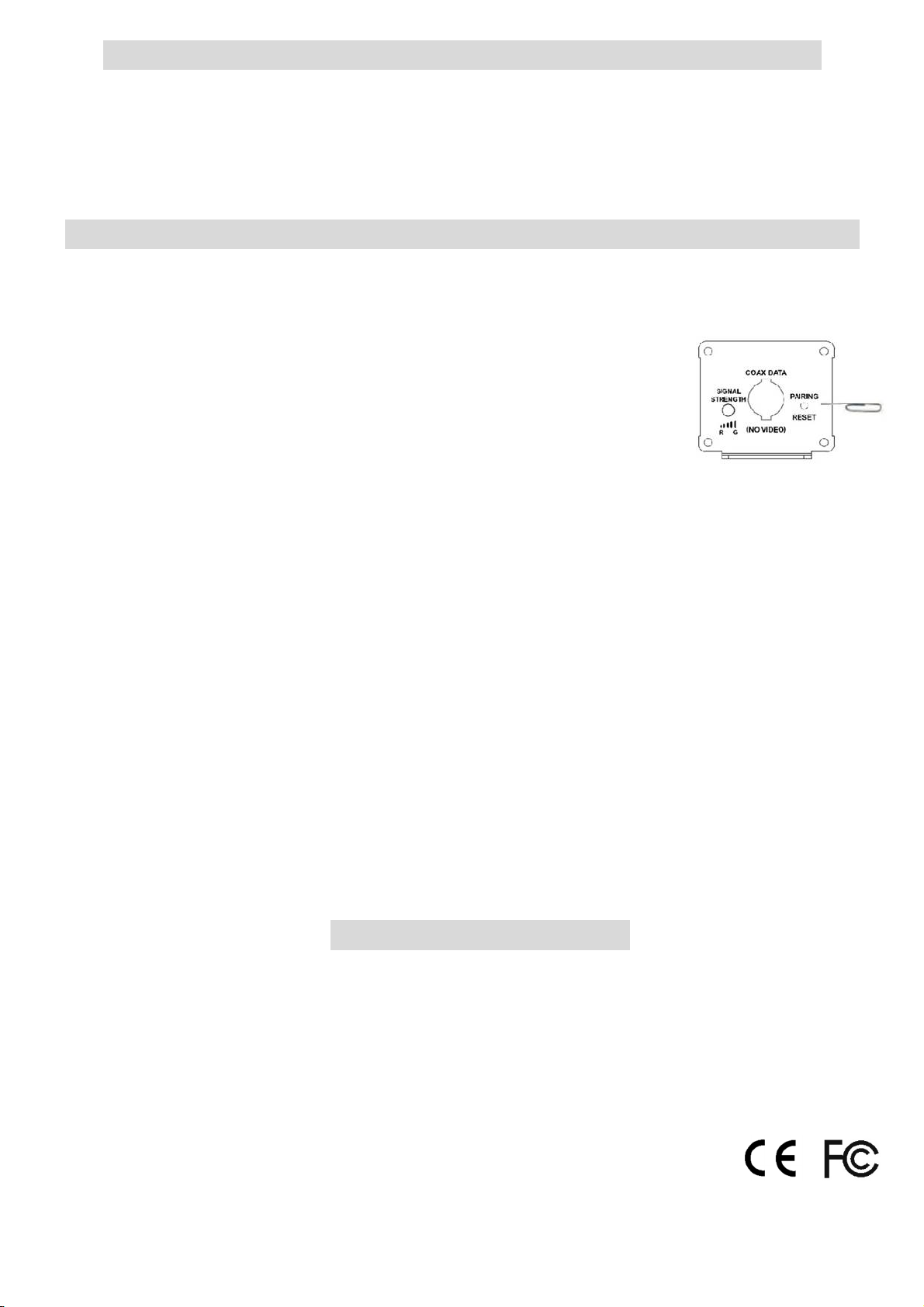
On transceiver at NVR side, using the straightened paper-clip to
access the small push button for 5 ~ 8 seconds, the color LED will
begin AMBER blinking once then OFF.
Step 3: Host/Master Side Create an New Network Group
On transceiver at NVR side, using the straightened paper-clip to access the small push
button for 1 ~ 3 seconds, the color LED will begin RED blinking.
Step 4: Slave Side Transceiver Leaving Current Network Group
On transceiver at Remote side (close to IP camera/device), using the straightened paper-
clip to access the small push button for 5 ~ 8 seconds, the color LED will begin AMBER
blinking once then OFF.
Step 5: Slave Side Transceiver Joining New Network Group
EOC/EOU transceivers at Remote side (close to IP camera/device), using the straightened
paper-clip to access the small push button for 1 ~ 3 seconds, the color LED will begin RED
blinking. The transceivers will find each other and starting the transmission.
Step 6: Adding Additional Transceiver Joining New Network Group
Repeat Step 4 and 5 to adding additional transceiver to new network group.
In Pairing Process Notice
1) In joining or leaving process, if you are not sure that joining or leaving has been
successful, you can RESET the transceiver (press the push button 12 to 30 seconds) ,
and repeat above steps.
2) After re-apply power or RESET transceiver, please wait color LED Amber blinking once
then GREEN, its means power on reset finished and you can do the pairing process.
3) The transceiver is from LEAVE to JOIN state (color LED RED blinking), it must join new
network group in 2 minutes, otherwise it will become LEAVE state again.
VER:20170224