Coral Coral Series Troubleshooting guide

Cabinet
Water Softener
Installation &
Operating Guide
Manual 001.5

Thank you for purchasing this Softener. We are sure that it will
provide you with trouble free service for many years to come. Please
use the following pages to assist you in the installation and set up of
your new Softener.
Identifying your Softener
Your softener will have a identification label fixed to the outer carton and
the control valve, this will look similar to the picture shown here.
The information listed can be read as follows:
4202035013
SNo
08090137 Mis
0919-255-760
Stock Number:
Manufacturers part number.
Serial No:
Serial No.
Id Code:
Softener type identification code.
Configuration:
Vessel size, Valve type & Controller type.
Identify the settings relevant to your softener from the chart below by looking at
the vessel size and controller type.
General Information
Valve connections.
255 Valve Inlet ¾” Outlet ¾” Drain ½” Barbed,
Overflow ½” Barbed
268 Valve Inlet 1” Outlet 1” Drain ¾” Barbed,
Overflow ½” Barbed
Power requirement 240V
(12V, 50Hz, 3 amp plug in transformer supplied).
Inlet water pressure Min 20 psi,
Max 120psi
Working temperature Max 40° C,
Protect from frost
The softener may or may not be supplied with connection hoses, drain hoses
or bypass valve sets depending on your supplier; these are available to order
separately if required from your supplier.
Planning Your Installation.
Please observe the regulations concerning the installation of your water
softener. For guidance check out the water regulations advisory service web site
(www.wras.co.uk) Check that you only have one rising main, that you have
allowed space for access to the unit for possible future maintenance and salt
replenishment. Check the water pressure; locate the rising main (stop cock) a
drain facility and a power supply.
Unless you are replacing an existing water softener, this installation will
require you to carry out plumbing work and may require an electrical outlet to
be fitted near the softener, this should be carried out by a qualified person.

Positioning the Softener.
Where possible the softener should be placed close to the rising main. Take
care to allow hard water take off points for a drinking water facility and /or an
outside tap. The distance between the drain and the Softener should be as short
as possible. Ensure that both the drain and overflow will not freeze or reach a
temperature above 40°C. If putting the Softener within a cupboard ensure that
the base is adequately supported. If the Softener is being installed within your
loft etc it is recommended to house the Softener within a tank capable of storing
at least 100 Litres with an overflow fitted. The overflow on the tank should be
below the Softener overflow and be a minimum of ¾” in size.
A single Check Valve.
A suitable check valve should be fitted. This will usually be in the
installation kit that can be ordered separately.
Check List.
Before you start the installation make sure that
you have all the necessary fittings. The
purchase of one of our standard installation kits
will normally ensure that you have everything
that you need for a typical installation
Water Pressure Test.
It is important that a pressure test is carried out.
High and low water pressure can result in either
damage to or failure of the Softener. Although
the Softener is tested to a pressure of 8 bar
(120psi), we recommend the fitting of a pressure
limiter should your pressure exceed 5 bar (70
psi). The minimum working pressure is 1.4 bar (20 psi)
Before starting the installation of the valves ensure that the stop cock is in
the closed position.

Connecting the Softener.
Once you have completed the installation of the valves set the valves as follows:
Softener Inlet and Outlet valve
CLOSED Bypass valve OPEN
You can now safely return the stop cock to the open position. Using the hoses
provided (if installation kit ordered) connect the straight end of the hose having
first inserted the washer provided to the softener inlet and outlet valves.
Connect the angled end to the Softener. The Softener inlets and outlets should
be indicated either with the words inlet or outlet or with an embossed
directional arrow on the Softener tails. Normally the Softener tails are in a
configuration of three with the centre normally being the waste outlet.
Waste Pipe Installation.
Connect the waste pipe to the waste outlet on the Softener and run the hose to
either an up stand or outside drain, a minimum air gap of 20mm must exist at the
end of the drain line. Softened water will have no adverse effect on a septic tank.
Should you need to extend the drain hose this can be done by connecting to a
15mm copper tube for a maximum run of 8 meters with a minimum daytime
pressure of 40 psi. Ensure that the drain hose is not kinked or obstructed in any
way as this will lead to an overflow of the softener. The drain pipe can run
uphill to a maximum of 1 Meter with a minimum water pressure of 40 psi.

Overflow Connection.
The overflow connection is the white ½” hose spigot on the rear or side of
the cabinet. A clip is not required for this connection. The overflow must be
run downhill through an outside wall without kinks or restrictions. It is
recommended the overflow hose be visible when it exits the outside wall.
Electrical Connection.
Connect the transformer provided to a continuous electrical supply with the
power off. Plug the flying lead from the transformer into the electrical
connection on the controller (see programming instructions). Ensure the
flying lead cannot get caught on the camshaft or any moving parts on the
Softener valve.
Preparing the Softener to go into service.
Now that all the connections have been completed put approximately 5 litres of
water into the brine tank. You may also at this point put a quantity of salt into
the tank. Do not allow the salt level in the brine tank to exceed the height of the
overflow. The amount of salt used will depend on the type and model of
Softener you have, you should never let the brine tank become completely
empty of salt and it is advisable to check the salt levels on a regular basis until
a usage pattern has been established, normally the salt level should be above
the water line.
Putting the Softener into service.
You should now complete any programming instructions that may apply to
your particular Softener. During the commissioning process and initial
regeneration you can confirm that the unit has no leaks from the installed
valves and that waste water runs freely. This regeneration will also assist in
cleaning any potential air locks that may be present within the system.
The regeneration will also reset any internal meter or timer devises that
dictate the frequency of the regeneration cycle.

Quick Set Up Guide
The main user guide should only be used for reference purposes,
please use this guide for initial programming.
Your softener should already have been set up with the basic settings in
the factory.
The only settings you should need to enter are the Time of Day, Day of
Week and the Water Hardness where applicable.
Button descriptions.
1.
Down arrow. Used to scroll
down or increment through
a group of choices.
2.
Set. Used to accept a setting to
store in the memory.
3.
Up arrow. Used to scroll up or
increment up through a group
of choices.
4.
Regenerate. Used to command
the controller to regenerate.
Before starting this process please ensure that the softener is connected
correctly to the water, waste and power supply.
Initial Power Up.
Plug the transformer into the rear of the control panel; this
is located to the left top corner of the panel if viewing from
the front. Once the power is connected the display may
briefly show the valve type (255 or 268). The valve type
will be printed on the side of the valve and should also
appear on the delivery documentation. On occasions the
display may flash between the time and regeneration
symbols, press the set button to clear this.
Note. During the set up process the display may revert to
normal mode (after 25 seconds).
By repeatedly pressing the up or down arrow button you
can scroll to the part of the set up programme you require.
If you receive an ERR3 message allow the cam shaft to
turn for a few moments and this code should disappear. If
the cam does not move check that the Cam Shaft is fitted
correctly and that the optical sensor is in position.

Set Time.
Press the set button. The TIME should now be flashing, use
the up and down arrows to set the correct time of day
(24hrs format). Once the correct time has been selected,
press the set button to confirm. The following will then be
displayed.
Set Day of the Week.
Press the set button to display the screen shown. The
display will flash, use the up and down buttons to advance
the arrow to underneath the correct day. Once under the
correct day press the set button to confirm. The following
will then be displayed.
Salt Setting
The system should have been pre-programmed to the
required setting but may need altering or resetting,
the default amount is 110 grams/Ltr.
To reset this press the set button to start the display
flashing and adjust the setting using the up and down
arrows to the correct setting (see 5.2)
On the 740 & 760 control you have options of S, L or H.
Time when system Regenerates.
This normally defaults to 2.00am but can easily be changed
to a more suitable time if required by pressing the square
set button to start the display flashing, adjusting the time
using the up and down arrows then press the square set
button to confirm. The following will then be displayed.
Calendar Override Days.
The system should have this pre-programmed to a
suggested number of days but this may need altering to suit
your needs. This function allows the filter bed to backwash
regardless of usage; this is to ensure that the filter bed
remains fresh.
Press the set button to start the display flashing then alter
the figure using the up and down arrows, then press the set
button to confirm the setting.
740 & 742 (Time) Controllers rely totally on this setting.

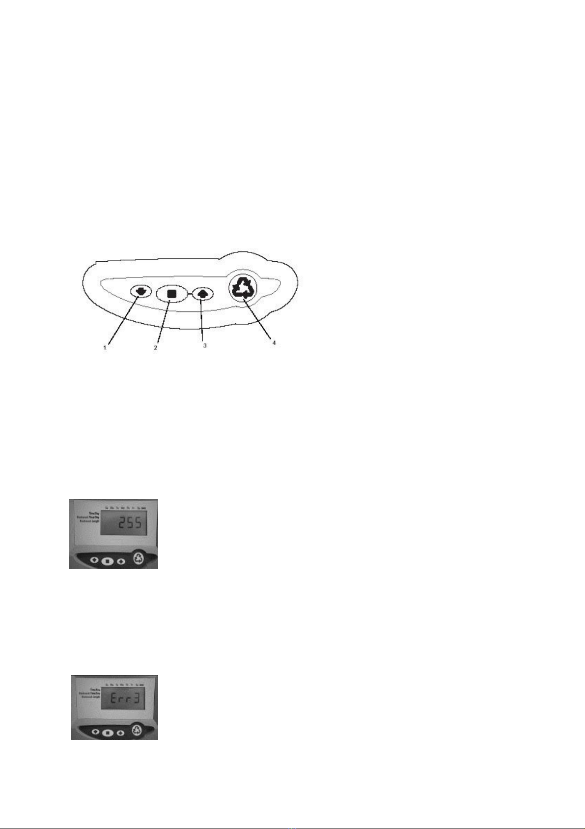
Hardness Setting (760 & 762 only)
The hardness setting will need to be set on site, the
setting is in ppm.
Press the set button to start the display flashing and
adjust the hardness value up or down using the up and
down arrows, when the correct figure is displayed press
the square button to set.
Capacity.
System capacity is displayed in kilograms of hardness
removed before regeneration is necessary. This should be
factory set but should it require setting you need to press
the set button to start the display flashing, then adjust the
figure using the up and down arrows and press the set
button to confirm the figure. Not adjustable on the 740 or
760 control.
Normal valve operation.
During normal valve operation the 740 & 742 will display the time of day,
the 760 will alternate between the time of day and volume of water remaining
in cubic meters before regeneration. The 762 will display the current water
flow and remaining capacity before regeneration.
Commissioning the Softener.
Open the outlet from the softener, press and hold the regeneration button (4)
until the cam starts to rotate, when the cam stops moving open the inlet to the
softener slowly until it is about a quarter open. Water will start flowing into the
softener and start purging the air from the softener, you will hear the air coming
out and eventually water will begin to run steadily from the drain line; you can
now fully open the inlet valve to the softener. Advance the regeneration cycle
to the (refill) position C8; do this by pressing the set button and up arrow
together at the same time and letting go, this advances the cycle to the next
position, repeat this until you reach C8. Now allow the valve to continue on it’s
own to the end of the cycle, this will purge air from the regenerant line and put
the correct amount of water into the salt chamber for its first regeneration.
Finally turn on a tap close to the softener and run the water, you may find there
is some colouration in the water; this will clear after a short while and is
normal. Your softener is now supplying soft water to your home, please bear in
mind it may take some time to reach all of the outlets in your home.
It is advised that you instigate a delayed regeneration for the first night
(see below)

Initiating a manual regeneration.
The softener can perform two different types of manual regeneration
either immediate or delayed.
Immediate Regeneration.
To perform an immediate regeneration you need to press and hold the
regeneration button for around five seconds until the cam starts to move and
the egg timer shows on the screen.
Delayed Regeneration.
Quickly press and let go of the regeneration button once. The regeneration
symbol will appear and flash on the display. A single regeneration will start at
the default or pre set regeneration time, if you wish to cancel this delayed
regeneration simply quickly press the regeneration button again an the
symbol will disappear from the display.
Resetting the Valve Programming.
Occasionally it maybe necessary to reset the valve to factory defaults.
The programmed valve type (softener) can be checked by pressing and holding
the SET and DOWN buttons simultaneously for 5 seconds. H0 and a volume is
displayed e.g. H0 100, the valve has been set as a softener. If in doubt contact
your supplier.
To reset the valve: with H0 displayed, press and hold the SET for 5 seconds
The valve type will now be shown e.g. 255, 268. Choose the correct valve (255
or 268) and press the SET button. Three dashes will now show on screen, this is
the volume and should be set accordingly using the up and down arrows set the
amount applicable to your system (see following programming details)
It will now be necessary to reset the time, day, regeneration time and override
days as above.
Standard
Vessel Size
613
1012
817 919
735
1023 835
935
1035
Type
Micro
Coral
Mistral
Coral
Swan
Mistral Swan
Swan Swan
Press ↓& ■together H0 appears) then press ■
Select type of valve
255 255
255
255
255
255 255
255
255
Media Volume to program (litres)
4
10 10 15 18 22 25 30 35
Parameter
Time of day (HH:MM) P1
Set on site
Day of week (DAY) P2
Set on site
Time of regeneration (HH:MM) P3
Set on site / Factory set default 2.00am
Calendar override days 740/760 P4
3/14
3/14
3/14
3/14 3/14
3/14 3/14
3/14 3/14
Regen interval if P4 set to 0 (740 ONLY) P5
Set on site if required
Salt amount (gms) P6
S
S
S
S
S
S
S
S
S
Capacity (Kg) 740 control (cannot change) P7
0.2
0.5
0.5
0.8
0.9
1.1 1.3 1.5
1.8
Capacity (Kg) 760 control P7
0.2
0.5
0.5
0.7
0.9
1.1 1.3
1.5
1.8
Hardness in ppm CaCO3 P8
Set on site 760 only

Water Save Models
Vessel Size
1012
919 735
835
935
1035
MIstral
Mistral
Swan
Type
Coral
Coral
Swan
Swan Swan
Swan
Mistral Mistral
Swan
Press ↓ & ■ together H0 appears) then press ■
Select type of valve
Valve / Control
255/762 255/762
255/762
255/762 255/762
255/762
255/762 268/762
268/762
Me ia volume to program
10
15
20 25
30
35 20 20 30
Level 1 Parameter
Time of Day (HH:MM) P1
Set on site (24hr clock)
Day of Week (DAY) P2
Set on site
Time of regeneration (HH:MM) P3
Factory efault 2:00 am
Calen ar Overi e Days P4
14
Salt setting P6
150
Capacity (Kg) P7
0.5
0.7
0.9 1.2
1.5
1.7 1.1 1.1 1.7
Har ness in ppm CaCO3 P8
Set on site
Level 3 Parameters (■ & ↑)
Backwash (Min) C1
2 2 3 3 4 4 3
3
4
Brine Draw (Min) C2
Calc at 12
Calc at 13
Calc at 13
Calc at 14
Calc at 17
Calc at 16
Calc at 13
Calc at 13
Calc at 17
Slow Rinse (Min) C3
40
40
46 43
51
44 46 46 51
Represurise (Min) C4
3 3 3 3 3 3 3
3
3
Fast Rinse 1 (Min) C5
2 2 3 3 4 4 3
3
4
Backwash 2 (Min) C6
1 1 1 1 1 1 1
1
1
Fast Rinse 2 (Min) C7
1 1 1 1 1 1 1
1
1
Refill (Min) C8
Calc at 4 Calc at 5 Calc at 7 Calc at 10
Calc at 10
Calc at 12
Calc at 9 Calc at 9
Calc at 10
Standard High Flow
The standard High Flow softener uses a 268 valve with 760 controller
and settings are as below.
Vessel Size
1012
919
Type
Coral
Coral
Press ↓& ■together H0 appears) then press ■
Select type of valve 255
255
Media Volume to program (litres)
10
15
Parameter
Time of day (HH:MM) P1 Set on Site
Day of week (DAY) P2 Set on Site
Time of regeneration (HH:MM)
P3
Set on Site (default 02:00)
Calendar override days
P4
14
Salt amount (gms)
P6
S
Capacity (Kg) 760 control
P7 0.5
0.7
Hardness in ppm CaCO3
P8
Set on Site

High Flow 762
If you have a High Flow Water save fitted with the 762 controller you will
need to use the settings below.
Vessel Size
1012 919 735 835
935
1035
1023
Type
Coral Coral
Swan Swan
Swan Swan
istral
Press↓ & ■ together H0 appears, then press ■
Select type of valve
Valve / Control
268/762 268/762
268/762
268/762
268/762 268/762
268/762
Me ia volume to program
10 15
20
25
30 35 20
Level 1 Parameter
Time of Day (HH:MM) P1
Set on site (24hr clock)
Day of Week (DAY) P2
Set on site
Time of regeneration (HH:MM) P3
Factory efault 2:00 am
Calen ar Overi e Days P4
14
Salt setting P6
150
Capacity (Kg) P7
0.5 0.7
0.9
1.2
1.5 1.7
0.9
Har ness in ppm CaCO3 P8
Set on site
Level 3 Parameters (■ & ↑)
Backwash (Min) C1
14 14
14
14
14 14 14
Brine Draw (Min) C2
Calc at 12 Calc at 13 Calc at 13 Calc at 14
Calc at 17 Calc at 16 Calc at 13
Slow Rinse (Min) C3
44 49
46
43
51 44 46
Represurise (Min) C4
3
3 3
3
3 3
3
Fast Rinse 1 (Min) C5
6
6 6
6
6 6
6
Backwash 2 (Min) C6
1
1 1
1
1 1
1
Fast Rinse 2 (Min) C7
1
1 1
1
1 1
1
Refill (Min) C8
Calc at 4 Calc at 5
Calc at 7
Calc at 9
Calc at 10 Calc at 12 Calc at 7
Coral Eco
If you have a Coral Eco Water Save fitted with the 762 controller you will need
to use the settings below.
Vessel Size
919
Type
Coral Eco
Press ↓ &
■
together H0 appears, then
■
Select type of valve
Valve / Control
255/762
Me ia volume to program
15
Level 1 Parameter
Time of Day (HH:MM) P1
Set on site (24hr clock)
Day of Week (DAY) P2
Set on site
Time of regeneration (HH:MM) P3
Factory efault 2:00 am
Calen ar Overi e Days P4
14
Salt setting P6
110
Capacity (Kg) P7
0.8
Har ness in ppm CaCO3 P8
Set on site
Level 3 Parameters (■ & ↑)
Backwash (Min) C1
1
Brine Draw (Min) C2
Calculate at 9
Slow Rinse (Min) C3
49
Represurise (Min) C4
3
Fast Rinse 1 (Min) C5
1
Backwash 2 (Min) C6
1
Fast Rinse 2 (Min) C7
1
Refill (Min) C8
Calculate at 4

Trouble shooting.
Following is a guide to some of the most common problems that may
arise; please consult this section before contacting your supplying dealer as
most problems are easily cured using this information.
Troubleshooting
Proble m Possible Cause Solution
ERR 1 is displayed Controller power has been Press the up arrow and the control
connected and the control is not should reset.
sure of the state of operation.
ERR 2 is displayed Controller power does not match Disconnect and reconnect the power
50 or 60 Hz. If the problem persists obtain the
appropriate controller or AC adapter
for either 50 or 60 Hz power.
ERR 3 is displayed Controller does not know the Wait for two minutes for the
position of the cam shaft. Camshaft
controller to return to home position.
should be rotating to find home The hour glass should be flashing
position. on the display indicating the motor
is running.
Camshaft is not turning during Check that the motor is connected.
ERR 3 display. Verify that the motor wire harness is
connected to the motor and
controller module. Verify the optical
sensor is connected and in place.
Verify that the motor gear is engaged
with the cam gear.
If everything is connected try
replacing in this order.
Wire harness.
Motor.
Optical sensor.
Controller.
If the camshaft is turning for more Verify that the optical sensor is in
than five minutes to find home place and connected to the harness.
position. Verify that the camshaft is
connected correctly.
Verify no debris is clogging any of
the cam slots.
If motor continues to rotate
indefinately replace the following in
this order.
Wire harness.
Motor.
Optical sensor.
Controller.
Four dashes displayed Power failure occurred. Press SET to reset time display.

Troubleshooting
Proble m Possible Cause Solution
1. Regenerant Tank Overflow A) Drain line restricted. Check the drain line is not blocked
or kinked.
See also 4 B) Uncontroller refill flow rate. Remove refill flow control to clean
ball and seat.
C) Air leak in regenerant line. Check all connections in regenerant
line for leaks.
D) Drain control clogged with resin Clean drain control.
or other debris.
E) Sinking air check ball (255 only).
Replace air check ball.
F) Incorrect drain control fitted.
Too small a drain control with a larger
injector may reduce the draw rates.
G) Regenerant valve disc 1 being Remove obstruction.
held open.
H) Valve disc 2 not closed during Remove obstruction.
regenerant draw causing a refill.
2. Water flow from drain or A) Flapper valve return spring weak.
Replace valve spring. (contact dealer)
regenerant line when in service.
B) Debris stopping flapper valve from
Remove debris.
closing.
3. Hard water after regeneration
A) Incorrect / failed regeneration. Repeat regeneration after checking
settings.
B) Leaking external bypass valve. Replace bypass (contact dealer)
C) O-Ting around riser damaged. Replace O-Ring (contact dealer)
D) Capacity too low due to incorrect
Check settings and adjust if required.
setting.
4. Will not draw regenerant or A) Low water pressure. Fit a pump (contact dealer)
intermittent or irregular draw. B) Drin line restricted. Check drain line is not blocked or
kinked.
C) Inlector plugged. Clean injector and screen.
D) Injector defective. Replace injector.
E) Flapper 2 &/or 3 not fully closed.
Remove debris, check flapper for
closing or replace. (contact dealer)
F) Air check prematurly closed. Put control into refill C8, replace
or repair air check if needed (contact
dealer)
5. System will not regenerate A) Power not connected. Connect power.
automatically. B) Defective motor. Replace motor (contact dealer)
C) Fouled or defective turbine. Clean or replace turbine.
D) Defective turbine cable. Replace turbine cable.
E) Turbine cable not positioned Push sensor into housing fully until
correctly. it clicks into place.
6. System regenerated at the A) Settings incorrect. Correct settings.
wrong time.
7. No conditioned water after A) No salt in tank or level too low. Add salt to regenerant tank, level
regeneration. should always be above the water
level.
B) Injector plugged. Clean injector and screen.
C) Air check closes prematurely. Check connections for air leaks and
check air check ball (255) floats.
See also 1 e & 4 f.
8. Backwashes at excessively A) Incorrect drain controller used. Replace with correct size.
low or high rate. B) Debris affecting valve operation. Remove drain controller and clean
volume to correct setting.

Troubleshooting
Proble m Possible Cause Solution
9. Valve will not draw brine. A) Low water pressure. Fit pump (contact dealer).
B) Drain line restricted. Check drain line is not blocked or
kinked.
C) Injector plugged. Clean injector and screen.
D) Injector defective. Replace injector.
E) Air check closes prematurely. Put control into brine draw C2 to
check. Repair or replace if needed.
10. Uses more or less salt than A) Foreign matter in valve causing Remove brine control and clean our
the setting. incorrect flow rates. any debris. Put system through a
regeneration to flush valve.
11. No water flow display on A) Bypass valve in bypass. Open bypass.
metered valves. B) Meter probe not connected to Connect correctly.
C) Restricted turbine rotation due to Remove turbine and clean. Turbine
debris in turbine. should rotate freely, if not replace it.
12. Run out of conditioned water
A) Impropper regeneration. Repeat regeneration after checking
between regenerations.
the correct regenerant dosage is set.
B) Incorrect regeneration setting. Set correct salt setting.
C) Incorrect hardness or capacity Set to correct values.
settings.
D) Water hardness has increased. Set hardness to correct value.
E) Restricted turbine rotation. See 11 c.
F) No or not enough salt in cabinet.
Salt level should be above water level.
This manual suits for next models
2
Table of contents
Other Coral Water Dispenser manuals
Popular Water Dispenser manuals by other brands

WaterSoft
WaterSoft AS24P Installation and operation manual

Atlas Filtri
Atlas Filtri AQUARIUS CS16H-1017 user manual

Henny Penny
Henny Penny CEC-103 Operator's manual

Pro Pond
Pro Pond UV110 Advantage Instructions for installation and use

WaterLogic
WaterLogic WL250 Troubleshooting

Murdock
Murdock H2O To Go BF15 Series Installation & maintenance instructions