omi CHA 1.3 Operating instructions

710.1759.01.07-00D 19/09/2018
1
Water / Water Heat exchanger
Výměník tepla voda / voda
CHA 1.3 to/až CHA 12
English
User and Maintenance Manual
Čeština
Manuál k provozu a údržbě
Save These Instructions
Tyto pokyny si uschovejte
O.M.I. srl
Via dell'Artigianato, 34 Fogliano (GO) 34070 ITALY
Tel: +390481488516 Fax: +390481489871
www.omi-italy.it
omi@omi-italy.it

710.1759.01.01-00D 19/09/2018
2
TABLE OF CONTENTS
1
GENERAL USER AND MAINTENANCE MANUAL ....................................................................... 3
1.1 HOW TO USE THIS MANUAL .................................................................................................... 3
1.2 GENERAL DESCRIPTIONS / INTENDED USE ............................................................................... 3
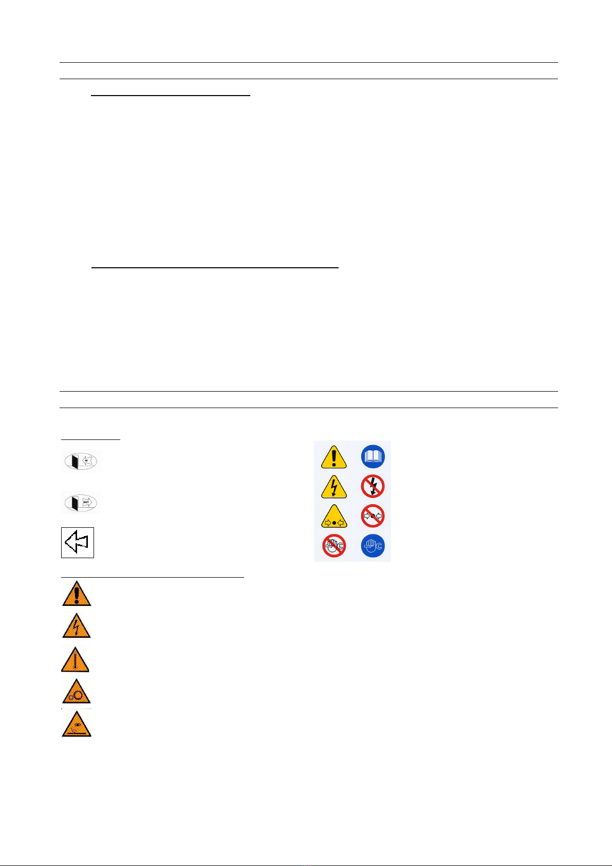
GENERAL SAFETY INSTRUCTIONS ........................................................................................ 3
3
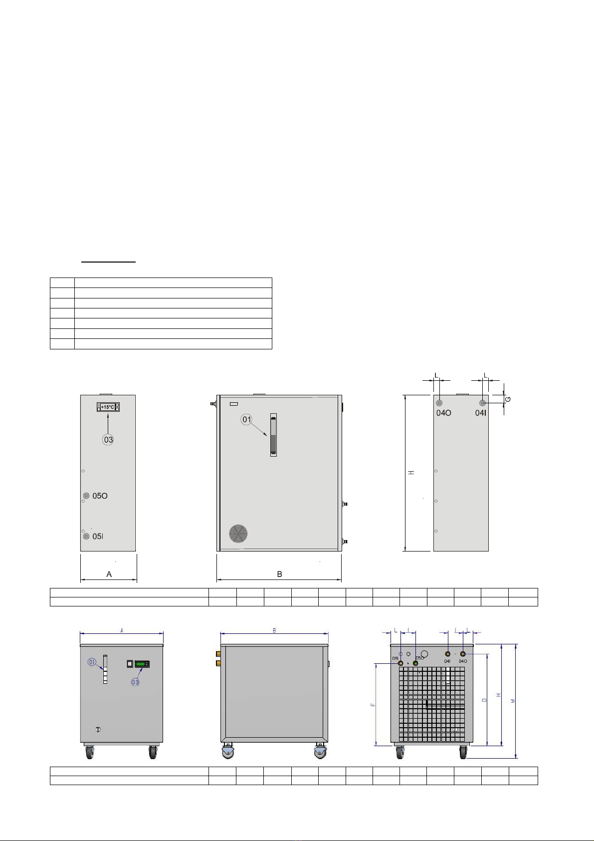
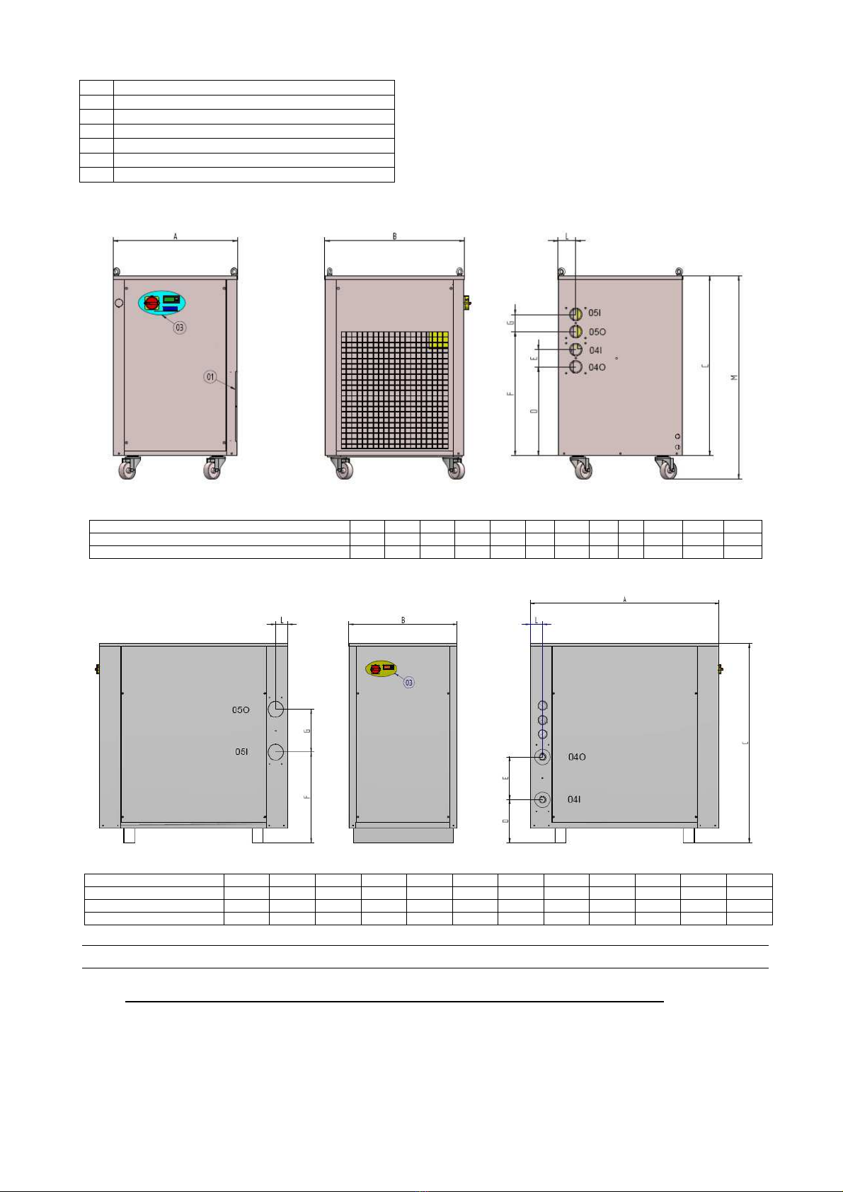
DESCRIPTION OF THE UNIT, COMPONENTS AND OPTIONS .................................................. 4
3.1 DESCRIPTION ........................................................................................................................ 4
3.2 REFRIGERATION CIRCUIT (HOT SIDE) ...................................................................................... 4
3.2.1 STANDARD COMPONENTS USED IN THE WATER COOLER ........................................................................ 4
3.3 HYDRAULIC CIRCUIT (CONSUMER CIRCUIT) .............................................................................. 5
3.3.1 STANDARD COMPONENTS USED IN THE WATER COOLER ........................................................................ 5
3.3.2 OPTIONS – HYDRAULIC CIRCUIT .......................................................................................................... 5
3.4 ELECTRIC CIRCUIT ................................................................................................................. 5
3.4.1 STANDARD COMPONENTS USED IN THE WATER COOLER ........................................................................ 5
3.4.2 OPTIONS – ELECTRIC CIRCUIT ............................................................................................................ 6
3.5 HOUSING .............................................................................................................................. 6
4
TRANSPORT / PACKING / STORAGE ..................................................................................... 7
4.1 REMOVING THE WATER COOLER FROM PACKAGING AND HANDLING ............................................ 7
4.2 DISPOSAL OF PACKING MATERIALS ......................................................................................... 8
4.3 STORAGE .............................................................................................................................. 8
5
INSTALLATION AND ASSEMBLY ............................................................................................ 8
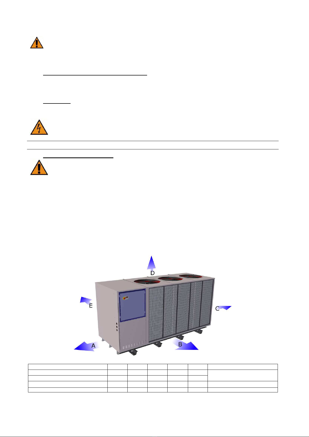
5.1 CHOOSING A LOCATION ......................................................................................................... 8
5.2 ASSEMBLY (CONNECTIONS) ....................................................................................................
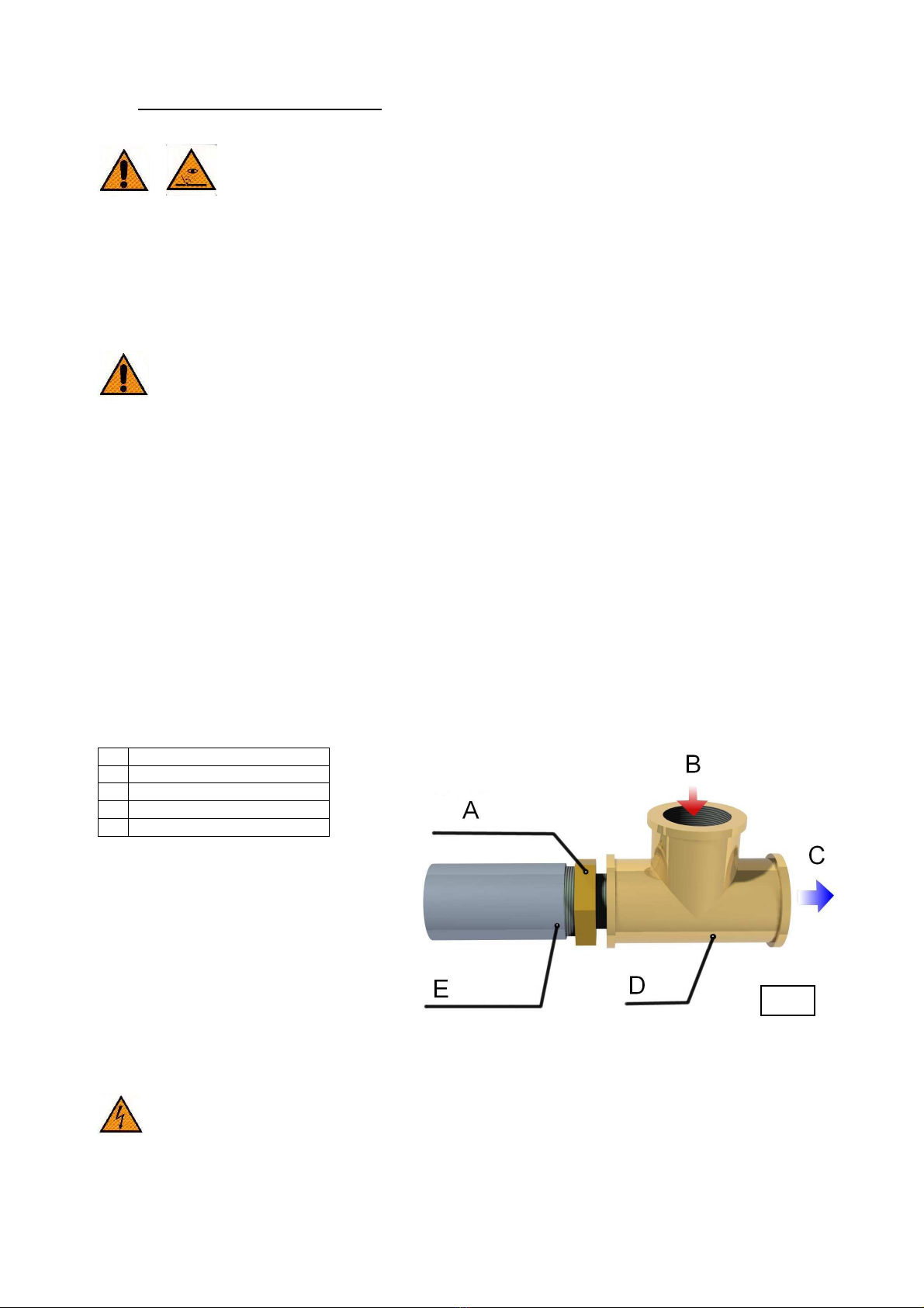
5.2.1 CONNECTION TO THE REFRIGERANT CIRCUIT (CONSUMER CIRCUIT) ....................................................... 9
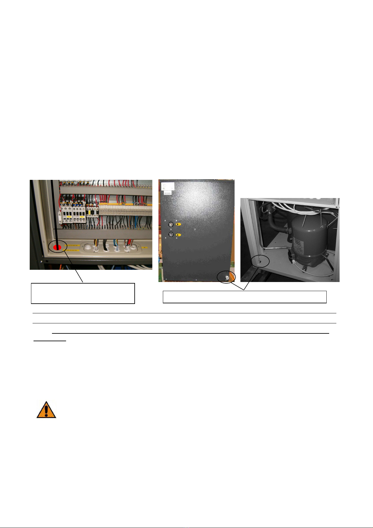
5.2.2 ELECTRIC CONNECTION ...................................................................................................................... 9
6
OPERATION ........................................................................................................................ 10
6.1 CHECK LIST FOR THE INITIAL START-UP OF WATER/WATER HEAT EXCHANGER SYSTEMS ............ 10
6.1.1 CHEC LIST MODELS CHA 1.3-11 ....................................................................................................... 10
6.1.2 CHEC LIST MODELS CHA 24-60 ........................................................................................................ 11
6.1.3 CHEC LIST MODELS CHA 99-129 ...................................................................................................... 11
6.2 OPERATING SETTINGS OF THE ELECTRONIC CONTROLLER ....................................................... 12
6.2.1 ELECTRONIC CONTROLLER ................................................................................................................ 12
6.3 SHUTTING DOWN THE WATER COOLER .................................................................................. 14
6.3.1 SWITCHING ON/OFF IN DAILY OPERATION .......................................................................................... 14
6.3.2 TEMPORARY DECOMMISSIONING ....................................................................................................... 14
6.3.3 DECOMMISSIONING FOR THE PURPOSE OF TRANSPORT ....................................................................... 14
7
MAINTENANCE ................................................................................................................... 14
7.1 MAINTENANCE ..................................................................................................................... 14
8
DISPOSAL ........................................................................................................................... 15
9
MALFUNCTIONS / TROUBLE SHOOTING ............................................................................. 15
.1 POSSIBLE ALARM SIGNALS AND THEIR RECTIFICATION ........................................................... 16
9.1.1 CONTROLLER TYPE “A”, “D”, (CHA 1.3 TO CHA 129) ............................................................................. 16
10
GENERAL TECHNICAL DATA / FUNKCE A TECHNICKÁ DATA ................................................ 34
10.1 TECHNICAL FEATURES / TECHNICKÉ FUNKCE ........................................................................ 34
10.2
HYDRAULIC CIRCUIT DATA / VLASTNOSTI ČERPADLA A NÁDRŽE ........................................... 34
10.3
COMPONENTS WITH A WEIGHT OF MORE THAN 20 KG
KOMPONENTY O HMOTNOSTI PŘESAHUJÍCÍ 20 KG ............................................................... 34
10.4
FLUIDS RECOMMENDATIONS / DOPORUČENÍ PRO KAPALINY ................................................ 35
11
DIAGRAMS / SCHÉMATA ..................................................................................................... 36
11.1
LEGEND / LEGENDA ......................................................................................................... 36
1
PED INFORMATION / PED INFORMACE .............................................................................. 38
13
INDIVIDUAL SPECIFICATION / INDIVIDUÁLNÍ SPECIFIKACE ........................................... 38

710.1759.01.01-00D 19/09/2018
3
1GENERAL USER AND MAINTENANCE MANUAL
1.1 HOW TO USE THIS MANUAL
This operating manual is intended for specialist staff involved in the installation, commissioning and
operation of CHA series. For the purposes of this operating manual, the general designation of “water
cooler” will be used for these devices.
This operating manual is an integral part of the water cooler. Every user, operator and service technician
must carefully read the information and instructions in this operating manual – especially those regarding
safety – before moving, installing, using, maintaining and disposing of the water cooler.
The owner of the water cooler must ensure that all works with and on the water cooler are only carried
out by properly trained personnel.
The installation and operating manual is divided into two sections that contains a detailed description of
the CHA series and additional information on the customer-specific design and model of your water
cooler, wherever these differ from the standard model. For example this is where you will find the
separate circuit diagram for this water cooler.
1. GENERAL DESCRIPTIONS / INTENDED USE
The water coolers have been developed in order to lower down economically with the lower energetic
consumption the liquid temperature, using the heat exchange between liquid and liquid.
The system’s overload determines a worsening of the water cooler performance (cooling capacity drop),
within the maximum usage limit, but does not compromise it’s safety.
A start and stop device (ON/OFF) allows the water cooler to be turned on and it permits its normal
functioning.
An electrical protection prevents the pump and other circuits parts damages.
The use of a water cooler is recommended for treatment of liquids in industrial, civil or commercial
cooling.
GENERAL SAFETY INSTRUCTIONS
SYMBOLS USED IN THE WATER COOLER/MANUAL
Water cooler
Liquid Inlet (Hot/Cold side)
WARNING DANGER
Read carefully the instructions,
break the power supply and
unload the parts under pressure
before any maintenance on the
unit.
Liquid Outlet (Hot/Cold side)
Fan Rotation Direction / Pump
Manual : Warning and danger symbols
GENERAL WARNING – GENERAL DANGER
General warning – general danger for the safety of people and objects
DANGER – ELECTRICAL POWER
Danger of electrocution during interventions on the parts of the water cooler and of the connected systems
/equipment with electrical power.
DANGER – HOT SURFACES/HIGH FLUID TEMPERATURE
Danger of burns due to the high temperatures of the hot parts of the water cooler and/or of the contained
fluids.
DANGER – MOVING PARTS
Danger of injury due to contact with the moving parts of the water cooler
DANGER – EYESIGHT DAMAGE
Danger of eyesight damage caused by the use of compressed air or liquid particles during cleaning
operations.
Any installation, use and maintenance operations must be done according to the instructions contained in the User and
Maintenance Manual and in accordance to the national rules. Any cleaning/maintenance operation which requires
access to the water cooler must be carried out by qualified and expert personnel who must be aware of all the
necessary precautions. Read the User and Maintenance Manual carefully before any operation. The water cooler has
been designed and manufactured to be used in conformity to the norms used in the country. In case of different use of
the water cooler or not in conformity to the User and Maintenance Manual, the Manufacturer can’t be considered
responsible.

710.1759.01.01-00D 19/09/2018
4
THE FOLLOWING POINTS MUST BE OBSERVED BEFORE COMMISSIONING AND WHILE OPERATING THE
WATER COOLER:
Familiarize yourself with all the operating controls.
The water cooler may be used solely for the intended purpose.
Make sure that all the working limits indicated in the operating and maintenance manual are
observed.
Use protective devices to check electrical insulation. Do not carry out any work on any parts
of the equipment that might be live with wet clothing, hands or feet.
Check at regular intervals whether the safety and control devices of the water cooler are
functioning properly.
Never hit the pipes located on the inside of the water cooler with objects of any kind.
Any maintenance operations not mentioned in the operating and maintenance manual must
not be carried out by personnel without the manufacturer’s prior written authorization if any
equipment components are under pressure.
Never spill or pour any cooling medium into the environment as this may cause damage to
health. Before the water cooler is resold, the cooling medium must be drained from the water
cooler using suitable equipment. Please contact customer service of the nearest dealer in this
connection.
The side panels of the water cooler must not be removed unless this is absolutely necessary.
Even if the side panels are only partially removed, isolate the water cooler from the electricity
supply and affix a sign to the control panel bearing the warning “Maintenance work on water
cooler in progress”. Replace the side panels as quickly as possible.
The components of the water cooler must not be modified in any way.
Bypassing the electrical protective devices may result in overloading of the water cooler.
Possible risks
CAUTION: The water cooler is equipped with a main switch.
The authorized installation technician must ensure that the water cooler has been connected
to the electricity mains in accordance with the standard EN 60204 and must ensure
compliance with all other applicable national standards.
Fire:
The electricity supply must be disconnected in the event of fire. Fire extinguishers or fire extinguishing
systems filled with powder, foam or carbon dioxide should be used by preference. The water cooler may
also be cooled with nebulised water. The use of water in large quantities must be avoided because if
there is leakage of refrigerant, the resulting chemical reaction – no matter how slight – may have a
corrosive effect.
In any case, it is necessary to reduce the ambient temperature and/or that of the water cooler and wait
for the temperature to fall before carrying out any work on the unit.
You are advised to include this device in your Fire Prevention Plan and Factory Safety Plan.
Make sure that suitable precautions have been implemented to avoid and combat any possible risks.
Excessive pressure on the liquid side:
This equipment isn’t supplied with safety devices.
The safety devices must be carried out by the installer.
Such devices will have to be carried out according to the applicable National Norms and to the limits
mentioned in this manual.
3DESCRIPTION OF THE UNIT, COMPONENTS AND OPTIONS
3.1 DESCRIPTION
The water cooler is supplied ready for connection. It consists of an housing, a cooling medium circuit
(consumer medium circuit) and an electrical engineering, including all the control, regulation and
monitoring devices required for fully automatic operation. The cooling media selected and used shall
comply with the environmental protection standards and the legal provisions.
3. REFRIGERATION CIRCUIT (HOT SIDE)
3. .1 STANDARD COMPONENTS USED IN THE WATER COOLER
The preceding abbreviations indicate the position in the drawings.
Not all components are contained in all models.
SC – Heat exchanger
Finned pack and heat exchange fitted out of the tank or stainless steel plate heat exchanger.
EVS – Solenoid valve
These valves maintain the constancy of the fluid temperature by regulating the flow of cold water to the
heat exchanger.

710.1759.01.01-00D 19/09/2018
5
3.3 HYDRAULIC CIRCUIT (CONSUMER CIRCUIT)
3.3.1 STANDARD COMPONENTS USED IN THE WATER COOLER
MF – Pressure gauge for cooling medium
The pressure gauge indicates the pressure at the outlet for the cooling medium.
P – Pump
Single-stage or multi-stage centrifugal pump of horizontal or vertical design, depending on output.
3.3. OPTIONS – HYDRAULIC CIRCUIT
BP – Automatic bypass / Overflow valve
The overflow valve guarantees the minimum throughput in the cooling medium circuit. In the continuous
flow and single-circuit systems this protects the pump.
BPM – Manual bypass
Using this bypass the minimum throughput in the cooling medium circuit can be manually adjusted.
CAA – Automatic cooling medium feed by means of float valve
The cooling medium is filled up automatically by the float valve if the level in the tank falls below the
minimum.
EV 1 – Solenoid valve 1 (connect without current) in return circuit
These valves should be used in open systems and when consumers are positioned at a higher level.
Generally used as a valve combination with VNR.
FL – Differential pressure switch
The flow controller located in the cooling medium inlet monitors the flow in the cooling medium and
consumer cycles and switches off the cooling system if the flow falls short off the minimum.
LVE – Float switch (for single and dual circuit systems only)
The float switch is located in the tank and monitors the cooling medium level. This ensures the constancy
of the water outlet temperature and the dry-run protection of the pump(s).
If the water level drops further and the minimum limit value is reached, the cooling system and pump(s)
are switched off. The water cooler cannot be switched on again until the cooling medium has been filled
up to the MAX mark on the level display.
RA – Tank heating
The tank heating system warms up the water in the tank. It can be used to achieve the correct operating
temperature in a short time if there is a low ambient temperature and no process heat.
TD – Digital thermometer in return circuit (systems with single and dual circuit)
The thermometer indicates the inlet temperature of the cooling medium.
VNR – Non-return valve in the supply line
These valves should be used in open systems and when consumers are positioned at a higher level.
Generally used as a valve combination with EV.
Dirt trap
If the cooling medium is expected to be contaminated by solids with a diameter > 1mm during operation,
a dirt trap with the appropriate mesh width has to be used. This should preferably be installed outside of
the equipment to allow an easy cleaning. It is important to note the flow direction. The dirt trap must be
cleaned at regular intervals after commissioning the water cooler.
Pump alternatives
A pump is provided as standard and supplies a pressure from 2 to 3 bar at a defined nominal flow rate.
Other pumps can of course be selected according to the project and then optimized to the desired flow
rate or pressure.
3.4 ELECTRIC CIRCUIT
3.4.1 STANDARD COMPONENTS USED IN THE WATER COOLER
IG – Main switch
When the main switch is turned off, the water cooler is current-free. The switch is located in the door of
the switch cabinet.
MTP – Motor protecting switch for pump
In the event of an increase in motor current or a short circuit, the motor protecting switch turns off and
interrupts the current supply. The motor protecting switch has to be turned on manually after the source
of the malfunction has been eliminated.
The motor protecting switch is located in the switch cabinet.

710.1759.01.01-00D 19/09/2018
6
ROO – Remote control
With the aid of an external contact, the water cooler can be switched off by the consumer or from a
control room. When this occurs, the main switch stays permanently in the "ON" position.
QE - Switch cabinet
The switch cabinet contains all the electrical components and the safety devices.
Connecting cable without plug.
Supplied ready for use with oilflex cable with 4 wires (3P/PEN) without plug.
TLT – Temperature controller
The temperature control and regulation is carried out by the temperature controller, which regulates the
temperature of the cooling medium according to the preset value. The temperature controller with digital
display is integrated in the door of the switch cabinet. Fault messages are displayed on the temperature
controller by means of codes.
3.4. OPTIONS – ELECTRIC CIRCUIT
Connecting cable with CEE plug
Supplied ready for use with oilflex cable and CEE plug 4 pole (3P+PEN) or 5-pole (3P+N+PE).
3.5 HOUSING
Legend :
01 Level
02 Power Supply
03 Control Panel
04I Water IN (hot side, application circuit)
04O
Water OUT (hot side, application circuit)
05I Water IN (cold side, external cooling circuit)
05O
Water OUT (cold side, external cooling circuit)
MODELS: CHA 1.3
MODELS A B H C D E F G I L M (Ø)
CHA 1.3 230 520 650 / / / / 35 / 25 / 12mm
MODELS: CHA 4, CHA 11
MODELS A B H C D E F G I L M (Ø)
CHA
4, 11
575
445
540
/
4 0
/
/
/
80
56
608
½”

710.1759.01.01-00D 19/09/2018
7
Legend :
01 Level
02 Power Supply
03 Control Panel
04I Water IN (hot side, application circuit)
04O
Water OUT (hot side, application circuit)
05I Water IN (cold side, external cooling circuit)
05O
Water OUT (cold side, external cooling circuit)
MODELS: CHA 24 to CHA 60
MODEL A B H C D E F G I L M (Ø)
CHA 24 580 650 / 845 41 80 583 80 / 82,5 61 1½”
CHA 40, 60 760 760 / 1250
767 100
72 100
/ 84 1360 1½”
MODELS: CHA to CHA 12
MODEL
A B H C D E F G I L M (Ø)
CHA 1325 760 / 1400 300 300 635 300 / 84 / 1½”
CHA 110 1325 760 / 1400 300 300 635 300 / 84 / 2“1/2“
CHA 12 1325 760 / 1400 300 300 635 300 / 84 / 2“1/2“
4TRANSPORT / PACKING / STORAGE
4.1 REMOVING THE WATER COOLER FROM PACKAGING AND HANDLING
Each water cooler is supplied in a reinforced carton on a wooden pallet. The water cooler must be kept in
an upright position at all times. NOTE: Tilting the water cooler may cause serious damage!
•Remove the strapping from the carton. Always wear safety gloves when using scissors or other
tools to cut the straps.
•Remove the carton.
•Raise the water cooler using suitable lifting gear.
NOTE: If the water cooler is fitted with eyebolts, these must be used for lifting it in accordance
with the applicable safety standards.

710.1759.01.01-00D 19/09/2018
8
If the water cooler is not fitted with eyebolts, the lifting gear must be appropriate for the
weight of the water cooler, as indicated on the identification plate and in the Annex.
All the handling operations must be carried out by qualified personnel only.
•Remove the pallet (if present).
•Place the water cooler in the desired location.
•Remove the operating manual, accessories and key from the water cooler
4. DISPOSAL OF PACKING MATERIALS
We recommend that you keep the original packaging for the water cooler in case it has to be transported
to another location or sent to a service centre. In any case, the waste packaging material must be
deposited with the responsible waste disposal companies.
4.3 STORAGE
The water cooler must be stored in rooms protected from atmospheric agents, in dry ambient and at
temperatures between + 5 and + 50 °C.
In case of storage for more than 12 months, before starting up the water cooler again, contact
the Manufacturer to check the preservation condition of the components of the water cooler
especially of the electric ones.
5INSTALLATION AND ASSEMBLY
5.1 CHOOSING A LOCATION
Install the unit in a protected dry area, free of fumes, dust or inflammable vapors, with non-explosive
atmosphere and in any case free of any element that may affect its correct functioning.
A suitable area to ensure a constant temperature in all seasons no lower than + 2°C and in any case no higher than +
40°C, even when the water cooler is operating. To use the water cooler at room temperatures lower than + 2°C or
higher than + 40°C, contact the manufacturer for all necessary variations.
We suggest an adequate ventilation not to change the ambient temperature, since the water cooler tends to heat up
the room.
Horizontal installation surfaces, flat and adequate to support the load of the water cooler. Bigger water coolers are
fitted with holes to be fixed on the floor at the tip of the supporting feet.
For outdoor installation protect the water coolers from any direct contact with atmospheric agents.
Position the water cooler to allow an easy reading of the control instruments and an easy access to the controls.
Adequate space for the installation of system accessory components.
Guarantee adequate free space above the water cooler.
(Image for example. For the other versions see the letters. B is always the front panel)
Models A (m) B (m) C (m) D (m) E (m) INSTALLATION
CHA 1.3 0.5 0.5 0.5 1 0.5 Indoor
CHA 4, CHA 11 1 1 1 1 1
CHA 24, CHA 40, CHA 60 1 1 1 1 1 Outdoor with protections
CHA
,
CHA
110,
CHA
12
1
1
1
1
1
Outdoor (suggest with protections)

710.1759.01.01-00D 19/09/2018
9
5. ASSEMBLY (CONNECTIONS)
5. .1 CONNECTION TO THE REFRIGERANT CIRCUIT (CONSUMER CIRCUIT)
All operations must be carried out by qualified personnel only.
Procedure: -In closed systems, make sure that the maximum obtainable cooling medium pressure in
the supply line does not cause a higher pressure level than the maximum permitted for
the water cooler.
-Check the cleanliness of the supply line and the piping system to be connected.
-Connect the water cooler with the consumer circuit; the identification of the joints
(cooling medium inlet/outlet) is indicated on the water cooler by means of the symbols
described in the introduction to the manual.
-Make all the connections, without rotating the sleeves located on the hose.
The cooling medium circuits of the Series CHA with tank are open to the atmosphere as
standard.
Use piping, connections and fastening components with a cross-section to match the capacity of the
water cooler and the possible volume flow. This should not be smaller than the diameter of the water
cooler connections.
In the case of rigid connections, check during the initial start-up of the water cooler that it is not subject
to any vibrations that might endanger the integrity of the components.
We also recommend that you should plan to install the following system components:
♦A bypass system with suitable valves upstream and downstream of the water cooler. This is
intended to allow use of the consumer circuit if you have to remove the water cooler from the
circuit, switch it off or use it in different ways at the same time.
♦A pipeline system with integrated filter near the water cooler to protect the pump against solid
matter and avoid deposits on the heat exchangers. The recommended mesh width for the water
coolers is 25µ with a maximum pressure loss at the filter of 1 bar.
♦In the models without flow monitoring, we suggest that you should install such a component if
the system exhibits losses or very high cooling medium consumption due to evaporation or
intervention by the operator. A further reason may be triggering of the solenoid valve to shut
down the system. The flow meter may trigger an alarm and enable immediate operator
intervention.
♦
On no account may the total pressure loss of the system exceed a value above that of the pump
performance.
A Male-male fitting
B From the loading line
C To supply line
D “T” fittings
E Outlet water cooler fitting
5. . ELECTRIC CONNECTION
The features of the main (size, protection system, ground connection) must comply with the Legislation
in force in the destination country, in relation to the electric features of the water cooler.
Below are the main general installation prescriptions.
All operations must be carried out by qualified personnel only.
The mains supply should be established with a rubber sheathed line connected to a TN-C system with
direct earthing.
30 V version (1 phase):
Connection with a single-phase, three-wire system (1/N/PE AC). The phase conductor and the neutral
conductor must be connected directly to the main switch of the water cooler.
The protective earth conductor must be connected to the earthing point of the water cooler.
Fig.1

710.1759.01.01-00D 19/09/2018
10
400 V version (3 phase):
Connection with a three-phase, four-wire system (3/PEN AC). The three-phase conductor must be
connected directly to the main switch of the water cooler. No neutral conductor is used. The PEN must be
connected to the earthing point of the water cooler.
If different mains voltages and frequencies are available, the country-specific features must be observed.
Make sure that the mains voltage and the frequency match the data on the identification plate of the
water cooler and agree with those in the table in the supplement and that the permitted values are not
exceeded. Check the mains for correct values and test the function of the earthing and protection
systems.
Install a general isolating switch for the electricity mains close to the water cooler. The connecting circuit
for the water cooler must be equipped with a circuit breaker and residual current protective device.
You can find information on the electrical power input values for the water cooler in the supplement.
Before you connect the water cooler to the mains, make sure that the general isolating switch
disconnects the water cooler from the electricity mains.
Pass the wires in the flexible polymer cable gland in the control panel (see photo for position) to connect
the power cable. Feed the connecting lead through the aperture in the rear plate (CHA 4 to CHA 60) on
the base of the water cooler. Lay the cable on the upright up to the gland on the base of the switch
cabinet (CHA to CHA 12 ). Inside the switch cabinet lay the cable in the installation duct up to the
main switch, where it is connected directly.
Check that the screws on the terminal clamps are firmly seated!
6OPERATION
6.1 CHECK LIST FOR THE INITIAL START-UP OF WATER/WATER HEAT EXCHANGER
SYSTEMS
6.1.1 CHECK LIST MODELS CHA 1.3-11
After extraordinary maintenance work or after turning off the main switch for more than 1 hour, each
start-up should be treated as an initial start-up.
The initial start-up calls for a number additional checks to ensure safe and reliable performance of the
system.
Before start-up
:
Make sure that the pump motor is not blocked: simply move the fan of the pump motor one
quarter of a turn.
Controller Type “A”, “D”, see 6. (CHA 1.3 to CHA 11)
1) Remove the lid panel and the two side panels.
2) Fill up the collection tank. Remove or unscrew the cap of the collection tank and fill up keeping the level indicator
under control or use “T” fittings. (Refer to Fig.1 point 5.2.1).
3) Open venting screw on pump head.
4) Tighten screw again once only water flows out.
5) Open the outlet interception valve and after that the inlet one of the water cooler (if present).
6) Bring the main switch of the water cooler to position “1” (the display will show OFF and the pump running).
7) Top up the tank if necessary. Then replace the tank cover.
8) After a few minutes, open the filler screw again carefully to remove any remaining air. Retighten the screw.
) Replace the lid panel and the two side panels.
Holes for the passage of power cable
Position of flexible gland for the
power cable

710.1759.01.01-00D 19/09/2018
11
10) Make sure that the water is able to circulate adequately. It the circuit might be interrupted by something such as
a valve, electrical valve, a filter or anything else, a by-pass circuit (automatic overflow valve) must be installed in
order to prevent damage to the pump.
11) Start-up the water cooler, pressing for 3 seconds button of controller type “A” or by pressing the button
of controller type “D”.
12) Wait for a couple of seconds until the water cooler reaches running conditions; running conditions are reached
when the temperature on the display reaches the set work field.
13) Verify, that the electric absorption of the water cooler is in accordance with the data on the label of the water
cooler and in the table contained in the supplement when the water cooler is in the running conditions set by the
Manufacturer.
6.1. CHECK LIST MODELS CHA 4-60
Controller Type “A”, “D”, see 6. (CHA 4 to CHA 60)
1) Remove front and two side.
2) Fill up the collection tank. Remove or unscrew the cap of the collection tank and fill up keeping the level indicator
under control or use “T” fittings. (Refer to Fig.1 point 5.2.1).
3) Open venting screw on pump head.
4) Tighten screw again once only water flows out.
5) Open the outlet interception valve and after that the inlet one of the water cooler (if present).
6) Open the switch cabinet with the key supplied (fastened to the main switch when the cooler is delivered).
7) Ensure that the motor protection switch (“MTP”) are in position “0”.
8) Fill the tank to the maximum (upper arrow, level indicator is located on the bottom right of the frame).
) Move the motor protection switch “MTP” to position “1”.
10) Make sure that the water is able to circulate adequately. It the circuit might be interrupted by something such as
a valve, electrical valve, a filter or anything else, a by-pass circuit (automatic overflow valve) must be installed in
order to prevent damage to the pump.
11) Lock the switch cabinet with the key.
12) Move the main switch of the cooler to position “1” (the temperature of the cooling medium appears on the
display).
Start-up the water cooler, pressing for 3 seconds button of controller type “A” or by pressing the button of
controller type “D”.
Never touch any part of the refrigerant circuit when the cooler is running!
13)Because the pump starts up immediately, make sure that the direction of rotation for the pump matches the
direction of the arrow on the casing. If it is rotating in the opposite direction, turn off the main switch of the cooler
immediately and arrange for the polarity of the cooler to be reversed.
14)After a few minutes carefully open the filler screw again in order to remove any residual air. Tighten the screw
again afterwards.
15)Wait until the cooler has attained the operating conditions. This is indicated when the display shows the preset
working range.
16)Check whether the pressure shown is within the limits specified for the pump. If not, take appropriate action to
ensure that pump is able to run within the specified limits.
17)Check the level in the tank and top up with cooling medium if required. Fasten the tank cap afterwards.
18)Check the inside of the cooler and the piping system for leakage or loose connections.
1 )Fit the front panel and the two side panels back onto the casing.
20)Check the preset target value. The water cooler is normally factory-set to the temperature required by the
customer.
21)When the cooler is within the operating conditions set by the manufacturer, check whether the current uptake of
the cooler matches the data indicated on the identification plate and those contained in the table in the
supplement.
6.1.3 CHECK LIST MODELS CHA 99-1 9
Controller Type “A”, “D”, see 6. (CHA 99 to CHA 1 9)
1) Remove front and two side.
2) Fill up the collection tank. Remove or unscrew the cap of the collection tank and fill up keeping the level indicator
under control or use “T” fittings. (Refer to Fig.1 point 5.2.1).
3) Open venting screw on pump head.
4) Tighten screw again once only water flows out.
5) Open the outlet interception valve and after that the inlet one of the water cooler (if present).
6) Open the switch cabinet with the key supplied (fastened to the main switch when the cooler is delivered).
7) Ensure that the motor protection switch (“MTP”) are in position “0”.
8) Fill the tank to the maximum (upper arrow, level indicator is located on the bottom right of the frame).
) Move the motor protection switch “MTP” to position “1”.
10) Make sure that the water is able to circulate adequately. It the circuit might be interrupted by something such as
a valve, electrical valve, a filter or anything else, a by-pass circuit (automatic overflow valve) must be installed in
order to prevent damage to the pump.
11) Lock the switch cabinet with the key.
12) Move the main switch of the cooler to position “1” (the temperature of the cooling medium appears on the
display).
13) Start-up the water cooler, pressing for 3 seconds button of controller type “A” or by pressing the button
of controller type “D”.

710.1759.01.01-00D 19/09/2018
12
Never touch any part of the refrigerant circuit when the cooler is running!
14) Because the pump starts up immediately, make sure that the direction of rotation for the pump matches the
direction of the arrow on the casing. If it is rotating in the opposite direction, turn off the main switch of the cooler
immediately and arrange for the polarity of the cooler to be reversed.
15) After a few minutes carefully open the filler screw again in order to remove any residual air. Tighten the screw
again afterwards.
16) Wait until the cooler has attained the operating conditions. This is indicated when the display shows the preset
working range.
17) Check whether the pressure shown is within the limits specified for the pump. If not, take appropriate action to
ensure that pump is able to run within the specified limits.
18) Check the level in the tank and top up with cooling medium if required. Fasten the tank cap afterwards.
1 ) Check the inside of the cooler and the piping system for leakage or loose connections.
20) Fit the front panel and the two side panels back onto the casing.
21) Check the preset target value. The water cooler is normally factory-set to the temperature required by the
customer.
22) When the cooler is within the operating conditions set by the manufacturer, check whether the current uptake of
the cooler matches the data indicated on the identification plate and those contained in the table in the
supplement.
6. OPERATING SETTINGS OF THE ELECTRONIC CONTROLLER
All operations must be carried out by qualified personnel only.
The water cooler is supplied pre-adjusted for normal operating conditions and normally does not require
any modifications, except for the setting the temperature of the cooling medium to the desired value.
Checking and any possible adaptation of the operating parameters is carried out via the controls on the
front of the water cooler and via the control panel. The water coolers are equipped with an operating
thermostat to maintain the cooling medium temperature at a constant value.
Type Controller display Models
Type A
CHA 1.3 to CHA 1 9
Symbole
Fan enabled (ON) – Programming Phase (flashes) – Anti-short cycle delay enabled
(flashes)
Defrost enabled (ON) – Programming Phase (flashes)
AUX
Second relay ON (ON)
A temperature alarm happened (ON)
Type Controller display Models
Type D
CHA 1.3 to CHA 1 9
Symbols
Regulation enabled (ON) – Anti-short-circuit delay active (flashes)
Degrees Celsius (ON) – Programming phase (flashes)
AUX
Second relay active (ON)
A temperature alarm has been triggered (ON)
6. .1 ELECTRONIC CONTROLLER
The operating thermostat is supplied in a pre-adjusted state according to the standard specifications of
the water cooler listed in the supplement. The operating thermostat controls both the temperature
adaptation functions and the other safety parameters (e.g. alarm management and the running time of
the electric motors). The complete list of parameters in not supplied to the customer because changes in
certain parameters may lead to problems affecting the reliability and characteristics of the water cooler.

710.1759.01.01-00D 19/09/2018
13
CONTROLLER TYPE “A”
Instructions for changing the parameters required by the user:
To modify SETPOINT value:
1) Press the key for 2 seconds ( LED start blinking).
2) Use and arrows to change the SETPOINT.
3) Press or wait 15s (time-out) without pressing any key.
To enter the “Pr1” User Level:
1) Press the + key for a few seconds ( and Leeds start blinking) the upper display
shows the first parameter.
2) Use and arrows to change the parameter.
3) Press key to modify its value.
4) Modify the value with and keys.
5) Press key again to confirm the new value, after a couple of seconds the next parameter will be
displayed.
6) To exit the programming: press + , when a parameter label is displayed, or wait 15s (time-
out) without pressing any key.
NOTE: The new parameter value is also stored even if during the time out no keys are pressed.
During the programming press to scroll the parameter code or increases its value.
The list of the parameters that can be changed using the above-mentioned procedure is the following:
Code Meaning Standard value Code Meaning Standard value
Set Set-point 15 Hy Differential 3
For others parameters, please contact the Manufacturer.
CONTROLLER TYPE “D”
Instructions for changing the parameters required by the user:
To modify SETPOINT value:
1) Press the key for 2 seconds (the LED starts to flash).
2) Use and arrows to change the SETPOINT.
3) Press or wait 15s (time-out) without pressing any key.
To enter the “Pr1” User Level:
1) Press the + key for a few seconds (the LED starts to flash) the upper display shows the
first parameter.
2) Use and arrows to change the parameter.
3) Press key to modify its value.
4) Modify the value with and keys.
5) Press key again to confirm the new value, after a couple of seconds the next parameter will be
displayed.
6) To exit the programming: press + , when a parameter label is displayed, or wait 15s (time-
out) without pressing any key.
NOTE: The new parameter value is also stored even if during the time out no keys are pressed.
During the programming press to scroll the parameter code or increases its value.
The list of the parameters that can be changed using the above-mentioned procedure is the following:
Code Meaning Standard value Code Meaning Standard value
Set Set-point 15 Hy Differential 3
For others parameters, please contact the Manufacturer.

710.1759.01.01-00D 19/09/2018
14
6.3 SHUTTING DOWN THE WATER COOLER
6.3.1 SWITCHING ON/OFF IN DAILY OPERATION
MODEL: CHA 1.3 to CHA 1 9 (Controller Type “A”, “D”, see 6. )
Via stand-by mode
1) Stop the water cooler keeping the key pressed (for 10 seconds) of controller type “A” or by
pressing the button of controller type “D”.
2) Move the main switch of the water cooler to position “0”
Via main switch
Move the main switch to position “0”. The system then switches off immediately. This procedure
should only be used in an emergency.
To avoid damage to the components, you should avoid operating the water cooler without
cooling medium at all costs, even for a short period of time! Neither may it be operated when
the liquid level displayed by the level indicator in the tank falls below the minimum limit.
Otherwise the operating cycle of the circulation pumps will stop!
If the display shows lower or higher temperatures than the standard values during operation, switch off
the water cooler immediately. Check the operating conditions before you contact the supplier or
manufacturer.
6.3. TEMPORARY DECOMMISSIONING
All operations must be carried out by qualified personnel only!
Follow this procedure if you need to shut down the water cooler:
•Stop the water cooler and permanently isolate it from the electricity mains.
•Once you have properly isolated the water cooler from the mains, you can disconnect the power
cable.
•Open the bypass valves (if present) for the cooling medium circuit and isolate the water cooler from
the circuit by closing the stop valves for the feed and return lines at the inlet and outlet as
necessary.
•Disconnect the machine from the cooling medium lines.
•Empty the tank and the internal cooling medium circuits
6.3.3 DECOMMISSIONING FOR THE PURPOSE OF TRANSPORT
All operations must be carried out by qualified personnel only!
Follow this procedure if you need to shut down the water cooler:
Stop the water cooler and permanently disconnect it from the electricity mains.
•Once you have properly isolated the water cooler from the mains, you can disconnect the power cable.
•Open the bypass valves (if present) for the cooling medium circuit and isolate the water cooler from
the circuit by closing the stop valves for the feed and return lines at the inlet and outlet as necessary.
•Disconnect the machine from the cooling medium lines.
•Empty the tank and the internal cooling medium circuits.
•If the water cooler has to be dispatched, use the original or a similar packaging and keep the water
cooler in an upright position.
•Remove the residual cooling medium from the water cooler, taking due account of its characteristics
and in compliance with the relevant legislation in force.
Before dismantling any electrical components, make sure that the water cooler is isolated
from the electricity mains and affix a warning sign to prevent the water cooler being
accidentally reconnected to the mains!.
To ensure that the water cooler operates properly and is suitably located, adhere to the safety
precautions described in the relevant sections.
7MAINTENANCE
7.1 MAINTENANCE
All maintenance interventions must be carried out by qualified personnel.
Isolate the water cooler from the mains before carrying out his operation.

710.1759.01.01-00D 19/09/2018
15
Carefully clean with compressed air using the suggested personal safety devices to avoid
damaging your eyes.
Do not use liquid substances to clean the bladed pack. Contact an authorized Service Center to
wash the pack.
Ordinary maintenance operations
Ordinary maintenance work does not involve any access to internal machine parts. Do not remove, even
partially, any covers of the machine parts for this purpose.
Every week:
1) Check from the outside whether the level of cooling medium in the tank is within the limits that
can be seen on the display on the side of the water cooler.
2) Check whether the cooling medium temperature matches the required temperature.
Every month:
1) Check the finned pack of the condenser from outside. If there are any deposits, clean them using
a compressed air jet with a pressure of not more than 3 bar.
2) Make sure that the compressor is not producing any unusual vibrations.
3) Check the cleanliness of the filter and clean it if necessary.
Every 4-6 months:
1) Check whether the current consumption of the compressor group is within the target values
indicated in these instructions.
2) Clean the fin pack of the condenser using a compressed air jet with a pressure of not more than 3
bar in order to remove all deposits that might impair its efficiency. The frequency of cleaning
depends on the quality of the ambient air; in any case we suggest that you clean the condenser
at the beginning of the summer. if necessary, straighten any bent aluminium fins.
3) Check the tightening of the screw on the clamps.
8DISPOSAL
All operations must be carried out by qualified personnel only.
The working life of such equipment is expected between 10 and 20 years.
Follow this procedure if you need to shut down the water cooler:
•Stop the water cooler and permanently isolate it from the electricity mains.
•Disconnect the power cable.
•Open the bypass valves (if present) for the liquid circuit and isolate the water cooler from the circuit
by closing the stop valves for the feed and return lines at the inlet and outlet as necessary.
•Disconnect the water cooler from the cooling medium lines.
•Empty the tank and the internal cooling medium circuits.
•If the water cooler has to be dispatched, use the original or similar packaging and keep the water
cooler in an upright position.
Before carrying out any work on the electrical parts, make sure that the main switch interrupts
the electricity supply to the water cooler and then affix appropriate warning signs to avoid the
machine being reconnected to the electricity mains!
Please consult the contents and the safety instructions in the relevant sections of these
instructions for details of the correct handling and storage of the water cooler!
Remove the residual cooling medium from the water cooler in a manner appropriate to its properties and
in accordance with the legislation in force.
If the water cooler has to be disposed of:
Send the water cooler to an approved waste disposal company in accordance with current environmental
protection legislation.
The other materials/waste constituents must be treated in line with the provisions of the valid legislation.
9MALFUNCTIONS / TROUBLE SHOOTING
All control and maintenance interventions must be carried out by qualified personnel!
If you have to take off or dismantle any components or assemblies, remove them and handle them with
suitable tools.
A number of possible problems are listed in the following table, together with notes on the causes and
recommendations on which remedial measures can be carried out.
Some of these operations are classified as extraordinary maintenance work and may require access to
internal parts of the water cooler and the removal of some parts.
The table in Section 10.3 of these instructions shows which components weigh more than 20 kg.

710.1759.01.01-00D 19/09/2018
16
You will find further information on safety precautions in the general warnings at the start of these
instructions.
Please note the following warnings in particular:
Do not remove (even only partially) the protective panels of the water cooler unless it is
necessary.
If the protective panels still have to be removed, disconnect the water cooler from its energy sources
(electricity and water), and affix a sign stating “Maintenance work on water cooler in progress” on the
operating panel.
Replace the protective panels afterwards as quickly as possible.
Wait at least 15 minutes before removing the protective panels so that the water cooler can cool
down. Certain internal components have a very high and dangerous operating temperature!
9.1 POSSIBLE ALARM SIGNALS AND THEIR RECTIFICATION
9.1.1 CONTROLLER TYPE “A”, “D”, (CHA 1.3 TO CHA 1 9)
No. Device
status
Alarm
code
Alarm
description
Possible cause Recommended actions Restore
(*)
1
Pump is
working,
solenoid
valve is
not
working
OFF
Unit is in Off
by remote
ON/OFF
Remote ON/OFF contact
is open or internal bridge
removed
Check bridge ROO and close the
contact
A
OFF Unit in stand
by
The unit is energized but
not switched on
Follow procedure to start up the
unit using button on controller
LA2
Antifreeze
alarm
(OPTIONAL)
Set point is too low for
actual system
If possible increase set point, or
check combination of flow,
temperature and antifreeze
percentage
Liquid flow too low Check right rotation of pump and
possible obstruction on liquid circuit
P1 Sensor P1
defective
Probe can be defective or
not well connected
Check connection and in case
change probe
2
Pump is
not
working,
solenoid
valve is
working
Pump is
blocked
The gear of the pump is
blocked by dusty or
corrosion
Try to move the axe of the pump
and after that switch on again
A
The motor of the pump is
internally protected
Switch off the unit for one hour and
try again after check the axe is not
blocked and there are no liquid
obstruction
Fuses can be defective Check the fuses
3
Pump and
solenoid
valve are
not
working
CA
Unit is in Off
by remote
ON/OFF
Remote ON/OFF contact
is closed
Check bridge ROO and open the
contact
A
digital input
alarm
Liquid flow too low
Check right rotation of the pump
and possible obstruction on liquid
circuit
Liquid in the tank too low Fill the tank
4
Pump and
solenoid
valve are
working
HA
High liquid
temperature
alarm
Dirty heat exchanger Clean the heat exchanger as
described in maintenance
A
Solenoid valve is not
working fine Check the solenoid valve
Required cooling capacity
is higher than nominal
Decrease the required cooling
capacity
Water inlet temperature
too high Check water inlet temperature
LA Low liquid
temperature
Ambient temperature too
low is decreasing liquid
temperature
The unit have to work in ambient
condition as specified in this manual
P2 Sensor P2
defective
Probe can be defective or
not well connected
Check connection and in case
change probe
(*) A Automatic restore at standard recovery condition – M Restore the alarm on the controller using the following
procedure

710.1759.01.01-00D 19/09/2018
17
HOW
TO VISUALISE A EVENT (CONTROLLER TYPE “A”)
CONTROLLER Type “A”
The LED warning alarm on shows that an alarm is taking place.
To see which kind of alarm, the max temperature (minimum) and the length, act as follow:
1) Press one of the two buttons or the display will show “HAL” (high temperature alarm)
or “LAL” (low temperature alarm) followed by Max. temperature or Min. temperature,
“tiM” will then appear (tiMe), followed by the “length” in h.mm.
2) At this point the instrument will show the temperature again
Note: the length defines the partial length in case the alarm is still on
HOW TO RESET AN ALARM EVENT
1) Press the button or , the display shows “HAL” (high temperature alarm) or “LAL” (low
temperature alarm).
2) Keep button pressed
3) The display shows: “rST”, which after 2 sec starts lightening, to show that the values have
been cancelled
HOW TO VISUALIZE A WARNING/ALARM EVENT (CONTROLLER TYPE “D”)
CONTROLLER Type “D”
The LED warning alarm on shows that an alarm is taking place.
To see which kind of alarm, the max temperature (minimum) and the length, act as follow:
1) Press one of the two buttons or the display will show “Hi” (high temperature alarm) or
“Lo“ (low temperature alarm) followed by Max. temperature or Min. temperature.
HOW TO RESET AN ALARM EVENT
1) Press the button or , the display shows “Hi” (high temperature alarm) or “Lo” (low
temperature alarm).
2) Keep button pressed
3) The display shows: “rST”, which after 2 sec starts lightening, to show that the values have
been cancelled

710.1759.01.01-00D 19/09/2018
18
OBSAH
1
OBECNÝ MANUÁL K PROVOZU A ÚDRŽBĚ ............................................................................ 19
1.1 JAK POUŽÍVAT TENTO MANUÁL .............................................................................................. 1
1.2 OBECNÝ POPIS / ZAMÝŠLENÉ POUŽITÍ ................................................................................... 1
OBECNÉ BEZPEČNOSTNÍ POKYNY ....................................................................................... 19
3 POPIS CHLADICÍ JEDNOTKY, SOUČÁSTÍ A PŘÍSLUŠENSTVÍ .................................................. 0
3.1 POPIS ................................................................................................................................. 20
3.2 CHLADICÍ OKRUH (HORKÉ STRANĚ) ....................................................................................... 20
3.2.1 STANDARDNÍ SOUČÁSTI POUŽÍVANÉ V CHLADICÍ JEDNOTCE ................................................................ 20
3.3 HYDRAULICKÝ OKRUH (SPOTŘEBITELSKÝ OKRUH) ................................................................... 21
3.3.1 STANDARDNÍ SOUČÁSTI POUŽÍVANÉ V CHLADICÍ JEDNOTCE ................................................................ 21
3.3.2 DOPLŇ Y – HYDRAULIC Ý O RUH...................................................................................................... 21
3.4 ELEKTRICKÝ OBVOD ............................................................................................................. 21
3.4.1 STANDARDNÍ SOUČÁSTI POUŽÍVANÉ V CHLADICÍ JEDNOTCE ................................................................ 21
3.4.2 DOPLŇ Y – ELE TRIC Ý OBVOD ........................................................................................................ 22
3.5
PLÁŠŤ ............................................................................................................................ 22
4 PŘEPRAVA / BALENÍ / SKLADOVÁNÍ .................................................................................... 3
4.1 ODSTRANĚNÍ BALENÍ A MANIPULACE S CHLADICÍ JEDNOTKOU ................................................. 23
4.2 LIKVIDACE OBALOVÝCH MATERIÁLŮ ...................................................................................... 24
4.3 SKLADOVÁNÍ ....................................................................................................................... 24
5 UMÍSTĚNÍ A INSTALACE ....................................................................................................... 4
5.1 VÝBĚR UMÍSTĚNÍ ................................................................................................................. 24
5.2 SESTAVENÍ (PŘIPOJENÍ) ....................................................................................................... 25
5.2.1 PŘIPOJENÍ O RUHU CHLADIVA (SPOTŘEBITELS Ý O RUH) ................................................................ 25
5.2.2 PŘIPOJENÍ ELE TRIC É ENERGII .................................................................................................... 25
6
PROVOZ .............................................................................................................................. 6
6.1 KONTROLNÍ SEZNAM PRO POČÁTEČNÍ SPUŠTĚNÍ VÝMĚNÍK TEPLA VODA / VODA ......................... 26
6.1.1 ONTROLNÍ SEZNAM PRO CHA 1.3 AŽ CHA 11 ..................................................................................... 26
6.2 PROVOZNÍ NASTAVENÍ PRO ELEKTRONICKOU ŘÍDICÍ JEDNOTKU ............................................... 28
6.2.1 ELE TRONIC OU ŘÍDICÍ JEDNOT U ................................................................................................... 28
6.3 VYPNUTÍ CHLADICÍ JEDNOTKY............................................................................................... 30
6.3.1 ZAPNUTÍ/VYPNUTÍ PŘI AŽDODENNÍM PROVOZU ................................................................................. 30
6.3.2 DOČASNÉ VYŘAZENÍ Z PROVOZU ....................................................................................................... 30
6.3.3 VYŘAZENÍ Z PROVOZU ZA ÚČELEM PŘEPRAVY ..................................................................................... 30
7
ÚDRŽBA .............................................................................................................................. 30
7.1 POSTUP ÚDRŽBY .................................................................................................................. 30
8
LIKVIDACE ......................................................................................................................... 31
9
ZÁVADY / ŘEŠENÍ PROBLÉMŮ ............................................................................................ 31
.1 MOŽNÉ VÝSTRAŽNÉ SIGNÁLY A JEJICH ŘEŠENÍ ....................................................................... 32
9.1.1 TYP ŘÍDICÍ JEDNOT Y „A“, „D“ (CHA 1.3 AŽ CHA 129) ......................................................................... 32
10
GENERAL TECHNICAL DATA / FUNKCE A TECHNICKÁ DATA ................................................ 34
10.1 TECHNICAL FEATURES / TECHNICKÉ FUNKCE ........................................................................ 34
10.2
HYDRAULIC CIRCUIT DATA / VLASTNOSTI ČERPADLA A NÁDRŽE ........................................... 34
10.3
COMPONENTS WITH A WEIGHT OF MORE THAN 20 KG / KOMPONENTY O HMOTNOSTI
PŘESAHUJÍCÍ 20 KG..................................................................................................................... 34
10.4
FLUIDS RECOMMENDATIONS / DOPORUČENÍ PRO KAPALINY ................................................ 35
11
DIAGRAMS / SCHÉMATA ..................................................................................................... 36
11.1
LEGEND / LEGENDA ......................................................................................................... 36
1
PED INFORMATION / PED INFORMACE .............................................................................. 38
13
INDIVIDUAL SPECIFICATION / INDIVIDUÁLNÍ SPECIFIKACE ........................................... 38

710.1759.01.01-00D 19/09/2018
19
1OBECNÝ MANUÁL K PROVOZU A ÚDRŽBĚ
1.1 JAK POUŽÍVAT TENTO MANUÁL
Tento manuál k provozu a údržbě je určen pro specialisty, kteří jsou zodpovědní za instalaci, uvádění do
provozu a provoz vodní chladič typu CHA. Pojem „chladicí jednotka“ se používá k označení všech těchto
zařízení.
Tento manuál k provozu a údržbě je nedílnou součástí chladicí jednotky. Každý uživatel, operátor a
servisní technik je povinen si před přepravou, instalací, používáním, prováděním údržby nebo likvidací
chladicí jednotky pečlivě pročíst informace a pokyny obsažené v tomto manuálu k provozu a údržbě,
obzvláště ty, které se týkají bezpečnosti.
Majitelé a operátoři chladicí jednotky mají povinnost postarat se o to, aby všechny práce na chladicí
jednotce prováděla pouze osoba s vhodnou specializovanou kvalifikací.
Provoz a údržba manuálu se dělí do dvou částí, které obsahují podrobný popis vodní chladič typu CHA s
příslušnými normami a s dalšími informacemi týkajícími se provedení pro konkrétního zákazníka nebo
specifický model chladicí jednotky, pokud se liší od standardního modelu. Najdete zde také informace pro
vybranou chladicí jednotku, například schéma okruhu.
1. OBECNÝ POPIS / ZAMÝŠLENÉ POUŽITÍ
Chladiče byly navrženy tak, aby snižovaly teplotu kapalin, ekonomicky as minimální spotřebou energie,
využívající výměnu tepla mezi kapalinou a kapalinou.
Přetížení systému v rámci maximálních limitů použití určuje zhoršení výkonu chladiče (snížení chladicí
kapacity), ale neovlivňuje jeho bezpečnost.
Zařízení pro spuštění a zastavení stroje (ON / OFF) umožňuje chladicí jednotky a určuje jeho normální
provoz.
Elektrická ochrana zabraňuje poškození čerpadla a dalších částí obvodu.
Pro úpravu kapalin v průmyslovém, civilním nebo komerčním chlazení se doporučuje použití chladiče
vody.
OBECNÉ BEZPEČNOSTNÍ POKYNY
SYMBOLY POUŽÍVANÉ V CHLADICÍ JEDNOTCE NEBO V MANUÁLU:
Chladicí jednotka
Vstup pro kapalinu
(teplá / studená strana)
VAROVÁNÍ NEBO NEBEZPEČÍ
Pečlivě si přečtěte tyto pokyny,
odpojte přívod elektrické energie a
uvolněte tlak z komponent pod
tlakem a teprve poté proveďte na
chladicí jednotce údržbu.
Vývod kapaliny
(teplá / studená strana)
Direzione Rotazione Pompa
Manuál k provozu a údržbě: varovné a výstražné symboly
OBECNÉ VAROVÁNÍ – OBECNÉ NEBEZPEČÍ:
Obecné varování – obecné nebezpečí pro osoby a majetek!
NEBEZPEČÍ – ELEKTRICKÝ PROUD:
Hrozí nebezpečí elektrické nehody při provádění prací na součástech chladicí jednotky a připojených
systémech/zařízeních, pokud je jednotka připojena k přívodu elektrické energie!
NEBEZPEČÍ – HORKÉ POVRCHY / VYSOKÁ TEPLOTA CHLADICÍHO MÉDIA:
Nebezpečí popálení kvůli vysoké teplotě žhavých součástí chladicí jednotky
a/nebo obsaženého chladicího média!
NEBEZPEČÍ – POHYBLIVÉ ČÁSTI:
Nebezpečí zranění při kontaktu s pohyblivými součástmi chladicí jednotky!
NEBEZPEČÍ – ZRANĚNÍ OČÍ:
Nebezpečí zranění očí stlačeným vzduchem nebo kapénkami během čištění!
Veškerá práce související s instalací, provozem a údržbou chladicí jednotky musí být prováděna v souladu
s pokyny obsaženými v manuálu k provozu a údržbě a v souladu s právními ustanoveními, které platí v
zemi, kde je zařízení nainstalováno. Veškeré čisticí/údržbářské práce, které vyžadují přístup k chladicí
jednotce, smí provádět výhradně kvalifikovaný specialista, který je informován o potřebných
preventivních opatřeních. Před prováděním jakýchkoli prací na zařízení si pečlivě přečtěte manuál k
provozu a údržbě. Chladicí jednotka je navržena a vyrobena takovým způsobem, aby odpovídala normám

710.1759.01.01-00D 19/09/2018
20
platným v příslušné zemi. Pokud bude chladicí jednotka použita k nesprávnému účelu nebo v rozporu s
manuálem k provozu a údržbě, výrobce za to nemůže nést odpovědnost
PŘED UVEDENÍM DO PROVOZU A PŘI PROVOZU CHLADICÍ JEDNOTKY MUSÍ BÝT DODRŽENY
NÁSLEDUJÍCÍ BODY:
Seznamte se s ovládacími prvky.
Chladicí jednotka smí být použita výhradně k zamýšleným účelům.
Ujistěte se, že budou dodrženy všechny pracovní limity uvedené v manuálu k provozu a údržbě.
Při kontrole elektrické instalace používejte ochranná zařízení. Neprovádějte práci na žádných
součástech zařízení, které mohou být pod proudem ve vlhkém oblečení, s mokrýma rukama nebo
nohama.
V pravidelných intervalech kontrolujte, zda bezpečnostní a řídicí zařízení chladicí jednotky fungují
správně.
Trubky uvnitř chladicí jednotky nesmí být nikdy zasaženy jakýmikoli objekty.
Údržbu, která není zmíněna v manuálu k provozu a údržbě, nesmí provádět personál bez
předchozího písemného povolení výrobce, pokud jsou jakékoli součásti zařízení pod tlakem.
Žádné chladicí médium se nikdy nesmí dostat do životního prostředí, protože by mohlo dojít k
ohrožení zdraví. Před opětovným prodejem chladicí jednotky musí být chladicí médium z chladicí
jednotky odčerpáno pomocí vhodného zařízení. V tomto ohledu se prosím obraťte na zákaznickou
službu nejbližšího dealera.
Boční panely chladicí jednotky nesmí být odstraňovány, pokud to není absolutně nezbytné. I v
případě, že budou boční panely odstraněny pouze částečně, izolujte chladicí jednotku od elektřiny a
připevněte na řídicí panel ceduli s varováním „Na chladicí jednotce probíhají práce údržby.“ Boční
panely co nejrychleji vraťte na své místo.
Komponenty chladicí jednotky je zakázáno jakkoli upravovat.
Obejití elektrických ochranných zařízení může mít za následek přetížení chladicí jednotky.
Možná rizika:
UPOZORNĚNÍ: Chladicí jednotka je vybavena hlavním vypínačem.
Autorizovaný montážní technik se musí postarat o to, aby byla chladicí jednotka připojena k
přívodu elektrického proudu v souladu s normou EN 60204 a musí zajistit dodržení všech
dalších platných národních norem.
Požár:
Přívod elektrické energie musí být v případě požáru odpojen. Preferuje se použití práškových nebo
pěnových hasicích přístrojů nebo hasicích přístrojů s oxidem uhličitým. Chladicí jednotku lze také
ochlazovat rozprašovanou vodou. Je nutné zabránit použití velkého množství vody, protože pokud by
došlo k úniku chladicí kapaliny, vznikla by chemická reakce s korozivním účinkem.
V každém případě je před prováděním jakýchkoli prací na jednotce nutné snížit okolní teplotu a/nebo
teplotu chladicí jednotky a počkat, než teplota klesne. Doporučujeme vám, abyste toto zařízení zahrnuli
do plánu požární prevence a továrního bezpečnostního plánu. Ujistěte se, že byla implementována
vhodná preventivní opatření, aby se zamezilo jakýmkoli možným rizikům.
Přílišný tlak na straně kapalný:
Toto zařízení není vybaveno bezpečnostními zařízeními.
Instalační technik odpovídá za instalaci bezpečnostních zařízení na straně chladicí kapaliny.
Tato zařízení musí splňovat platné národní předpisy a limity uvedené v návodu k použití a údržbě.
3 POPIS CHLADICÍ JEDNOTKY, SOUČÁSTÍ A PŘÍSLUŠENSTVÍ
3.1 POPIS
Chladicí jednotka je připravena k připojení. Je tvořena skříní, okruhem chladicího média (spotřebitelský
okruh) a elektrickým obvodem, který obsahuje všechna řídicí a monitorovací zařízení nutná k
automatickému provozu. Vybrané a použité chladicí médium musí plnit ekologické normy a právní
ustanovení.
3. CHLADICÍ OKRUH (HORKÉ STRANĚ)
3. .1 STANDARDNÍ SOUČÁSTI POUŽÍVANÉ V CHLADICÍ JEDNOTCE
V nákresech jsou použity následující zkratky.
Některé modely neobsahují všechny součásti.
SC – Výměník tepla
Žebrovaná trubka výměník tepla namontováno vně nádrže nebo deskový výměník z nerezové oceli.
EVS – Solenoidový ventil
Tyto ventily udržují stálost teploty kapaliny regulováním průtoku studené vody do výměníku tepla.
This manual suits for next models
8
Table of contents
Languages:
Popular Water Dispenser manuals by other brands

Elkay
Elkay VRC8FR 1C Series Installation, care & use manual

Pentair
Pentair Everpure QL1-BH2 user manual

Whirlpool
Whirlpool 8LIECH-SCSSFP5W user manual

Halsey Taylor
Halsey Taylor HVR8HD Series owner's manual

Halsey Taylor
Halsey Taylor OVL OVL-II ER-Q owner's manual

DS Services of America
DS Services of America 200K Series How to Clean