CORBERO CTWG15CD User manual

杨振美 2023-04-18
莫 红 2023-04-18
冯健纯 2023-04-18
高锡忠 2023-04-18
林志亮 2023-04-18
1
共 1 6 页
(CK-XBY-KBL 塑料机电子式)
CTWG15CD / CTWG30CD
Obrigado por ter escolhido o nosso produto.
Por favor, leia atentamente este manual antes de instalar e ulizar este produto.
Obrigado por ter escolhido o nosso produto.
Por favor, leia atentamente este manual antes de instalar e ulizar este produto.
CTWG15CD / CTWG30CD


Outlet Pipe(red)
Heating Indicator Light
Smart Light
Inlet Pipe(blue)
Control Panel
ELCB

Installation Precautions
Cautions
The wall for mounting the appliance shall be able to withstand at least fourfold
of the total mass of the appliance when filled with water. Take reliable reinforce-
ment measures when necessary.
Appliance should be installed as close as possible to frequent water points to
reduce heat loss from pipelines.
Adequate space must be left around the appliance to facilitate future mainte-
nance. When the appliance is installed above the ceiling, the ceiling shall be
provided with a movable plate and a maintenance window for removing and
installing the appliance.
Safety drainage measures such as floor drains must be in place to prevent
leakage of appliances from causing damage to other facilities.
It must be installed indoors and where the temperature of the link is above 0℃,
so as not to cause ice to break the water pipe of the tank.
There should be no inflammable or explosive objects around the installation
appliance.
Do not reverse connection of inlet and outlet water pipes. Sealing gaskets
should be installed at the interface of inlet and outlet water pipes, and the
rotating force should be appropriate during installation.
A safety valve (a pressure relief device) shall be installed at the inlet of the
appliance through which water may flow out of the relief valve drain pipe. The
outlet of the relief valve shall be maintained in contact with the atmosphere.
The drain pipe should be securely fixed at the outlet of the relief valve.
The attachments provided by our company must be used.
Sockets providing power to appliances must be reliably grounded. Do not install
power sockets in places that may be damp or wet.
The installation must be performed by professional installation personnel.
Packing List
Name
Quantity
Name
Water Heater 1 Bracket 1
Manual 1 Sealing Gasket 1
Safety Valve
1
Plastic Expansion Tube 2
Quantity
Water Drain Pipe
Fastening Screw
1
2

62
Equipment installation
① After the installation position of the appliance is determined, drill two holes with
a spacing of 62mm and a diameter of φ10mm in the horizontal direction of the wall
according to the size as shown in the following figure, and the hole depth shall not
be less than 70mm. Insert two plastic expansion tubes into the hole, and secure
the host mounting plate with fastening screws.
② Align the two hanging holes on the back of the appliance with the two hooks of
the hanging plate and pull down with force to make the hanging holes hang into the
hook.
Install the wall hole
Water Heater
Wall
Hanging Hole
Water Heater Bracket
Fastening Screw
Plastic Expansion Tube
Warning: The appliance must be hung securely to prevent personal injury and
property damage from falling.
Tube Connection
The specification of inlet and outlet water interface of this appliance is GI/2.
Connect pipes according to the following figure.
① Connect the gasketed safety valve attached to the inlet port of the appliance
with the arrow pointing in the direction of flow.
② Insert the drain pipe into the bottom of the
safety valve outlet, the other end of the continuous
downward to the safe drainage (such as into the
floor drain), the drain pipe should be unobstructed
installation, and the safety valve outlet is connected
with the atmosphere.
③ When the water inlet pressure is more than 0.55
MPa, an additional safety valve should be added
on the water inlet pipe.
Methods of Installation
(Take the above sink water heater installation diagram as an example)
15L
8kg 11.2kg
30 to 80℃
28L
380x380x325mm 440x440x390mm
220-240V~ / 50-60Hz
0.75MPa
PX4
1500W
CTWG15CD CTWG30CD

Multiple Outlet Connection
If the user wants to implement a multi-pipe supply system, please refer to the method
shown on the drawing for connection.
Safety Valve
Inlet Valve
Piping and Electrical Connection
Reference Diagram
Safety Valve
Thread Screw
Drain Handle
Pressure Relief
Opening
Water Inlet Joint
Notice
The rated pressure of safety valve is 0.8MPa. When the pressure of the pipeline system
exceeds its rated pressure, the safety valve will automatically drain and relieve pressure,
and water flow out of the outlet is a normal phenomenon.
The drain pipe connected to the pressure relief device (safety valve) must be installed in a
continuous downward direction in a frost-free environment. (Lead the other end continuously
downward to a safe drain (such as into a floor drain) to prevent hot water from flowing out).
The blue is the water inlet, and the red is the water outlet.
If the hot water pipe is too long, it should be insulated to reduce heat loss.
When setting a power socket, determine the installation position according to the actual
length of the cable.
Test Run
① After all installation is completed, open all valves in the pipeline, then open the hot
water tap, fill the appliance with water and close the hot water tap. Check whether the
pipes are leaking. If so, reconnect the pipes.
② Unscrew the stop screw at the handle of the safety valve, pull the handle of the
safety valve, and check whether the water discharge of the safety valve is smooth
(continuous water outlet means normal).
③ After confirming normal operation, switch on the power and run the appliance acco-
rding to the operation method section. Power off and disconnect when all is well.
Ground Connection
L-entrada
Operador
Controlador
Controlador da
temperatura
Elemento de aquecimento
Sensor de temperatura
Castanho
Amarelo/verde
Azul

The pressure relief temperature of the safety valve may cause scalding.
Scalding may occur if the temperature is set to more than 50℃. It must
be mixed with cold water before use.
The appliance uses 220-240V~/50-60Hz power supply.
Do not pull or plug the power cord with wet hands.
Do not close the water inlet valve, and do not turn on the power supply
when the appliance is not filled with water, so as not to damage the
appliance.
The safe service life is 8 years. When the product is still used after the
safe service life, it may cause fire or injury due to the deterioration of
quality as years of disrepair.
Do not allow children to operate the appliance to avoid accidental injury.
Caution
Warning
Notice
Please confirm the actual water temperature before use to avoid too
low or too high water temperature.
Turn the thermostat to the lowest temperature before unplugging the
power cord.
Periodically pull the safety valve handle to check whether the relief
valve drain is unblocked. If not, please contact us.
In cold areas, when the appliance is not used for a long time in winter,
the water should be emptied to prevent the appliance from freezing
and damage.
When the appliance is installed under the sink, check frequently
whether the sink is leaking to avoid danger to the appliance.

Water Injection
When the water heater use at the first time or used again after outage for a long time,
should inject water. Open all valves in pipeline, and then turn on the hot water tap.
When the water continuously flow, it replies that water heater have been filled with
water. Turn off the hot water tap, kept cold water pipe valve opening, make sure that
cold water could automatically add after hot water usage. And make appliance has
always been filled with water.
Method of Usage
Schematic diagram of the control panel
45...80

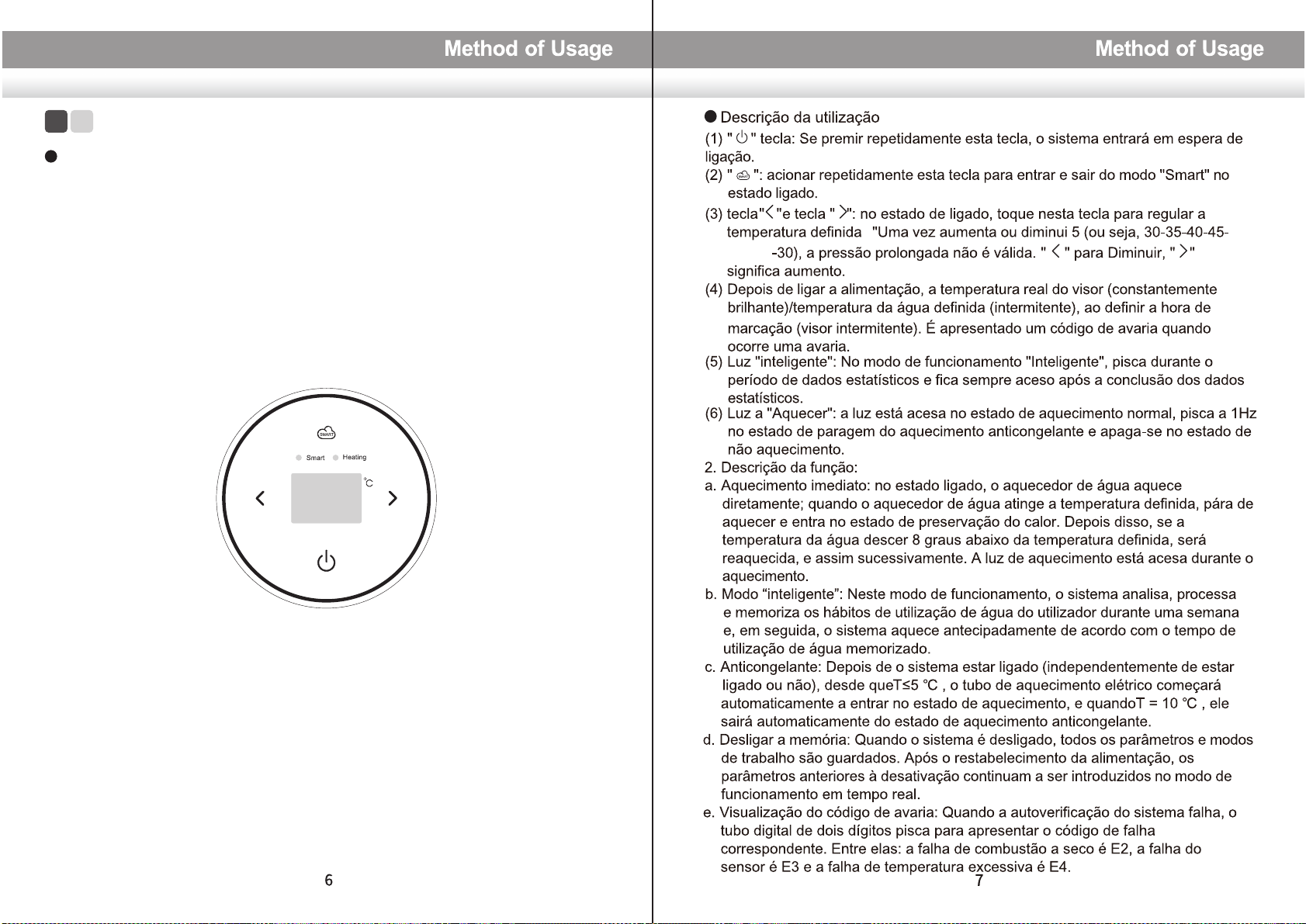
(1) “ ” key: Repeatedly operate this key and the system will enter power-on-wait.
(2) “ ” key: repeatedly operate this key to enter and exit the “Smart” mode in the
power-on state.
(3) “ ” key and “ ” key: in the power-on state, touch this key to adjust the set
temperature.One time increases or decreases 5 (ie 30-35-40-45...80-30), long
press is invalid. “ ” for Decrease, “ ” means increase.
(4) After the power is turned on, the actual temperature of the display (constantly
bright)/set water temperature (flashing), when setting the appointment time
(flashing display). A fault code is displayed when a fault occurs.
(5) “Smart ” light: In the “Smart ” working mode, it flashes during the statistical data
period, and is always on after the statistical data is completed.
(6) “Heating” light: the light is on in normal heating state, flashes at 1Hz in antifreeze
heating in shutdown state, and goes out in non-heating state.
2. Function description:
a. Immediate heating: in the power-on state, the water heater directly heats, when
the water heater reaches the set temperature, it stops heating and enters the
heat preservation state. After that, if the water temperature drops below the set
temperature by 8 degrees, it will be reheated, and so on. The heating light is on
when heating.
b. “Smart ”mode: In this working mode, the system analyzes, processes and
memorizes the user's water usage habits for a week, and then the system will
heat in advance according to the memorized water usage time.
c. Antifreeze: After the system is powered on (regardless of whether it is turned on
or not), as long as T≤5℃, the electric heating tube will automatically start to enter
the heating state, and when T=10℃, it will automatically exit the antifreeze
heating state.
d. Power-off memory: When the system is powered off, all parameters and working
modes are saved. After the power is restored, the parameters before power-off
are still entered into the real-time working mode.
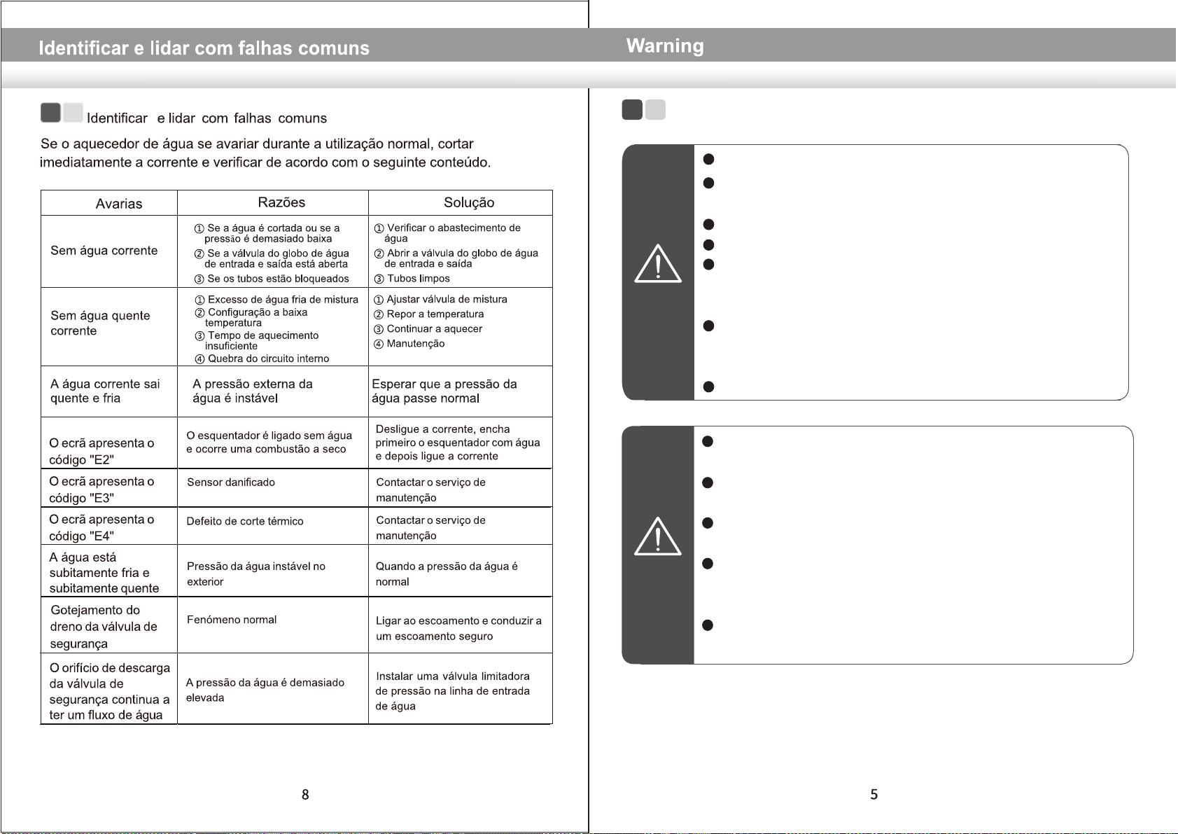
e. Fault code display: When the system self-check fails, the two-digit digital tube
flashes to display the corresponding fault code. Among them: the dry burning
fault is E2, the sensor fault is E3, and the over-temperature fault is E4.
Description of Usage

Identify and Deal with Common Faults
If water heater broke down during normal use, please immediately cut off the power,
check according to the following content.
The water is not hot
(no display on the display)
no water
①Whether there is no water outside
or the water pressure is too low
②Whether the water inlet and outlet
shut-off valve is open
③Whether the pipeline is blocked
①Whether there is no water outside
or the water pressure is too low
②Whether the water inlet and outlet
shut-off valve is open
③Whether the pipeline is blocked
①Power failure or the power switch is
in the off position
②Internal circuit failure
①Check the power supply line
②Contact the maintenance department
The water is not hot
(Display works normally)
①The heating temperature is set too low
②The heating time is too short-10
③Mixing valve failure
④Internal circuit failure
①Increase the heating temperature
②Continue heating
③Replace the mixing valve
④Contact the maintenance department
Display shows code "E2"
The water heater is powered on without
water, and dry burning occurs
Damaged sensor
Thermal cut-out fault
Turn off the power, fill the water heater
with water first, and then turn on the
power
Contact the maintenance department
The water is suddenly
cold and suddenly hot
Drip from safety valve
drain
Unstable water pressure outside
Normal phenomenon
When the water pressure is normal
Connect to drain and lead to safe drain
The discharge port of the
safety valve continues to
flow water
Water pressure too high Install a pressure limiting valve on
the water inlet line
Display shows code "E3"
Display shows code "E4"
fault phenomenon cause of issue Approach
Contact the maintenance department
60

Cleaning
Descaling
Use dry cloth or wet cloth to dip a little of neutral cleaner to wipe water heater
surface, do not use gasoline or other solvents, mustn't spray water.
According to the local water quality condition, when water heater using a certain time
(usually 1 months), need to remove dirty scale: first turn off the water heater, close
the inlet valve, separate the connection between inlet and outlet, empty inner tank
water. After descaling, reinstall the inner tank connection between inlet and outlet.
Draining
With long-term outage or maintenance, first cut off the power supply, turn off the inlet
water valve, separate the connection between the inlet and outlet water pipe, empty
it by upside down, and reinstall the connection between the inner tank and the
connection between inlet and outlet water pipe. When using again, the inner tank
must be filled with water before connecting the power supply.
Wiring Diagram

10
Product Specifications
15L
8kg 11.2kg
30 to 80℃
28L
380x380x325mm 440x440x390mm
Model
Parameter
Rated Capacity
Net Weight(anhydrous condition)
Rated Power
Product Size(AxBxCmm)
Rated Voltage
Rated Pressure
Waterproofing Grade
Setting Temperature Range
220-240V~ / 50-60Hz
0.75MPa
PX4
1500W
Replace Magnesium Anode
Caution
The magnesium anode is to prevent corrosion in the inner tank, which is a consumptive
part. After installation, need to check once a year. If the magnesium anode is about to
run out or has been run out, should be replaced immediately with the same specifications
of the magnesium anode, to ensure the service life of the water heater.
Pull out the power cord before maintaining.
Non-professional maintenance personnel disassembly, maintenance
and modification of water heater shall be strictly forbidden.
The safety valve (pressure relief devices) need to regular take action,
to remove calcium carbonate sedimentary and prove that it is not
blocked. If blocked, please repair in time.
Drainage must be within the container under the water temperature
below 40 ℃, avoid scald.
CTWG15CD CTWG30CD

Panel de control

Tubo de saída
(vermelho)
Indicador de
aquecimento

CTWG15CD CTWG30CD
15L
8kg 11.2kg
30 to 80℃
28L
380x380x325mm 440x440x390mm
220-240V~ / 50-60Hz
0.75MPa
PX4
1500W
10

L-entrada L-salida
Operador
Disyuntor térmico
Elemento de calentamiento
Sensores de
temperatura
Controlador

60

45...80
This manual suits for next models
1
Table of contents
Other CORBERO Water Heater manuals
Popular Water Heater manuals by other brands

VESTEL
VESTEL TRV 50 Service manual

Hoval
Hoval CombiVal CR 200 operating instructions

Ariston
Ariston 45 Assembly and operation instructions

Cordivari
Cordivari Bollyterm Home user manual

Atlantic
Atlantic Zeneo 50 Installation and Maintenance

Rinnai
Rinnai SENTO 350 Instructions for use installation and servicing

Gorenje
Gorenje TGR 30-200 N Instructions for use

IBC
IBC IBT 52 Installation & operating manual

TESY
TESY GCVS 1004420 B11 TSR Instructions for use and maintenance

clage
clage CEX 9-U ELECTRONIC MPS Installing instructions

Haier
Haier HP200M3 Installation and service manual

Chronomite
Chronomite ER-42 480 3P Series Installation and operation instruction manual