QUICKGUIDE TO ACCESS CONTROL INSTALLATION
For further assistance, call (800) OK CORBY
access control
systems
Equipment Checklist
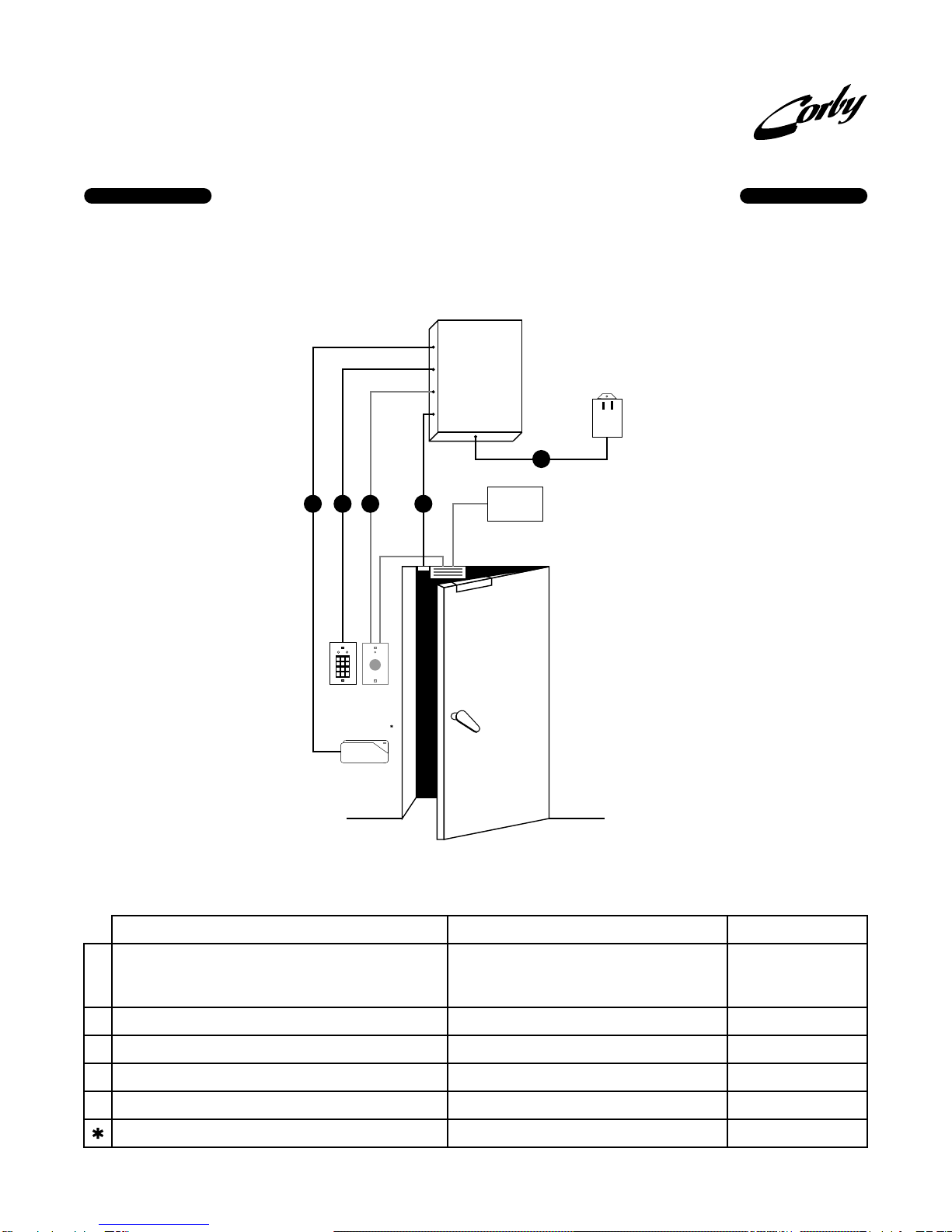
SYSTEM 2 PANELS
2003Supports 1 Door, 280 Users with names - 485 without
names maximum, 256 Time/Holiday Cells, Full Duplex
RS232,
Auxiliary Relay #1 and Voltage Output #1, Forced
Entry, & Door Ajar Inputs, Emergency Drop Input,
Request-To-Exit Input, and One Zone Input. Includes
heavy-duty steel Cabinet, 48 Character LCD,
16.5 VAC Transformer, 12 V 4AH stand-by battery,
Installation manual
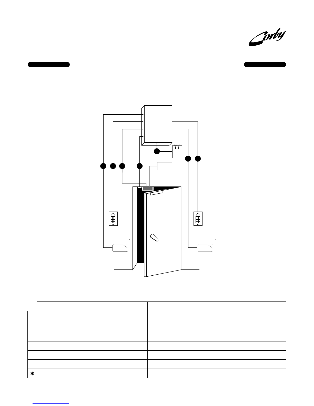
2016Same as 2003 but adds: Second Door, Anti-Passback,
Temporary Users, One Zone Input, Auxiliary Relay #2,
One Voltage Output, Large RAM, RS485, eight (8)
additional Time Schedules and code and schedule
linkage to auxiliary outputs.
2020Upgrade Kit for P/N 2003: Adds Second Door,
Anti-Passback, Temporary Users, One Zone Input,
Auxiliary Relay #2, One Voltage Output, Large RAM,
RS485, eight (8) additional Time Schedules and code
and schedule linkage to auxiliary outputs.
4010Single-gang, flush mount with one green LED
4014Hidden View with tamper switch, One Green and Red
LED, Single-gang, surface mount
4063Heavy-Duty, flush mount w/ on e Green & Red LED
4012Aluminum cover, surface mount w/ one Green & Red
LED. Also includes 12VDC night light
4062Cast metal Heavy-Duty mounted in a Lock-box and on
a goose neck. Includes one Green and Red LED
4064Cast metal Heavy-Duty mounted in a Lock-box.
Includes one Green and Red LED
4066Cast metal, flush mount, Heavy-Duty with one Green
and Red LED
4302Single-gang, flush mount, with one Green LED
4303Single-gang, flush mount, with one Green & Red LED
4304Narrow, flush mount with one Green LED
430 5Narrow, flush mount with one Green and Red LED
4306Reader Head and one Green LED
4307Narrow, (black) surface mount with bi-color LED,
back-lit read head and mounting hardware
4320Chip assembled on a key-ring with Corby logo
4321Chip Only - For use with badges, photo ID cards etc.
4323Roll of double stick tape (dots) for adhering Data Chip -
100 pieces per roll (required for 4321)
4042Indoor/Outdoor swipe (beige)
4044Indoor/Outdoor swipe (black)
4046Indoor/Outdoor Insertion reader (black)
(4052 mounting b racket recommended)
4047Plain white, Photo ID
4048Corby logo Photo ID
4049Standard 30 bit card
4073Indoor, surface mount, swipe (black)
4075Indoor/Outdoor, surface mount, swipe, (beige)
4074Credit card size, for use with 4073, 4075 readers
4150Indoor/Outdoor, surface mount, swipe, (black)
4151Credit card size
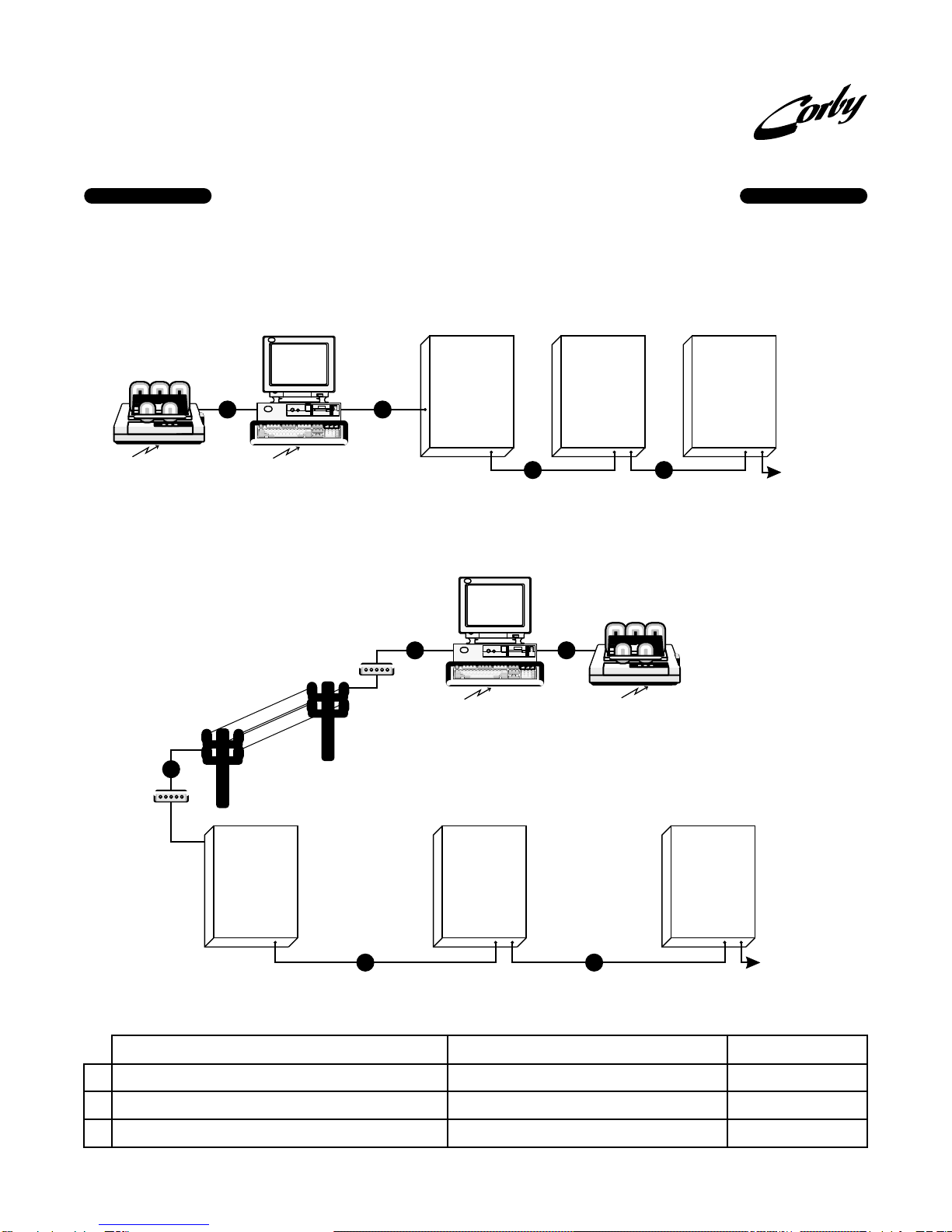
4126Phone modem. Connect One at the circuit board
location and one to the VDT or PC
4252Magnetic Lock for doors that swing out.
4253Door strike for metal or wood door frames
4035Heavy-duty exit button (LED illuminated)
4135Light-duty exit button
40946-12 Volt with 6A lead acid battery and transformer
4056Line Extender Module. Increases distance 500 feet.
4255Magnetic Door Contact
^
^ Large RAM supports additional users.
(4060 mounting hardware kit recommended)
KEYPADS
Indoor
Outdoor
READERS
Data Chip Readers
Data Chips
Wiegand Readers
Wiegand Cards
HID Proximity Readers
Magnetic Stripe Readers
Magnetic Stripe Cards
Bar Code Readers
Bar Code Cards
MODEMS
12 VDC DOOR LOCKS (Require 4094 Power Supply)
EXIT DEVICES
POWER SUPPLIES
MISCELLANEOUS
Generic 26-bit Wiegand Card Capability,
4173Indoor/Outdoor, 10" - 27" read range
4174Indoor/Outdoor, 1" - 9" read range
4175Indoor/Outdoor, thinline 2" - 4" read range
4176Indoor/Outdoor, mullion 2" - 5" read range
4170Keyfob, 26 bit
4171Credit card size w/ badge slot, 26 bit
4172Credit card size, graphics quality for photo ID, 26 bit
4118Short haul up to 1 mile.
2018Data Chip Programming Wand for faster and easier
programming of Data Chips
HID Proximity Cards
OPTIONAL PROGRAMMING DEVICE
4100Video Display Terminal