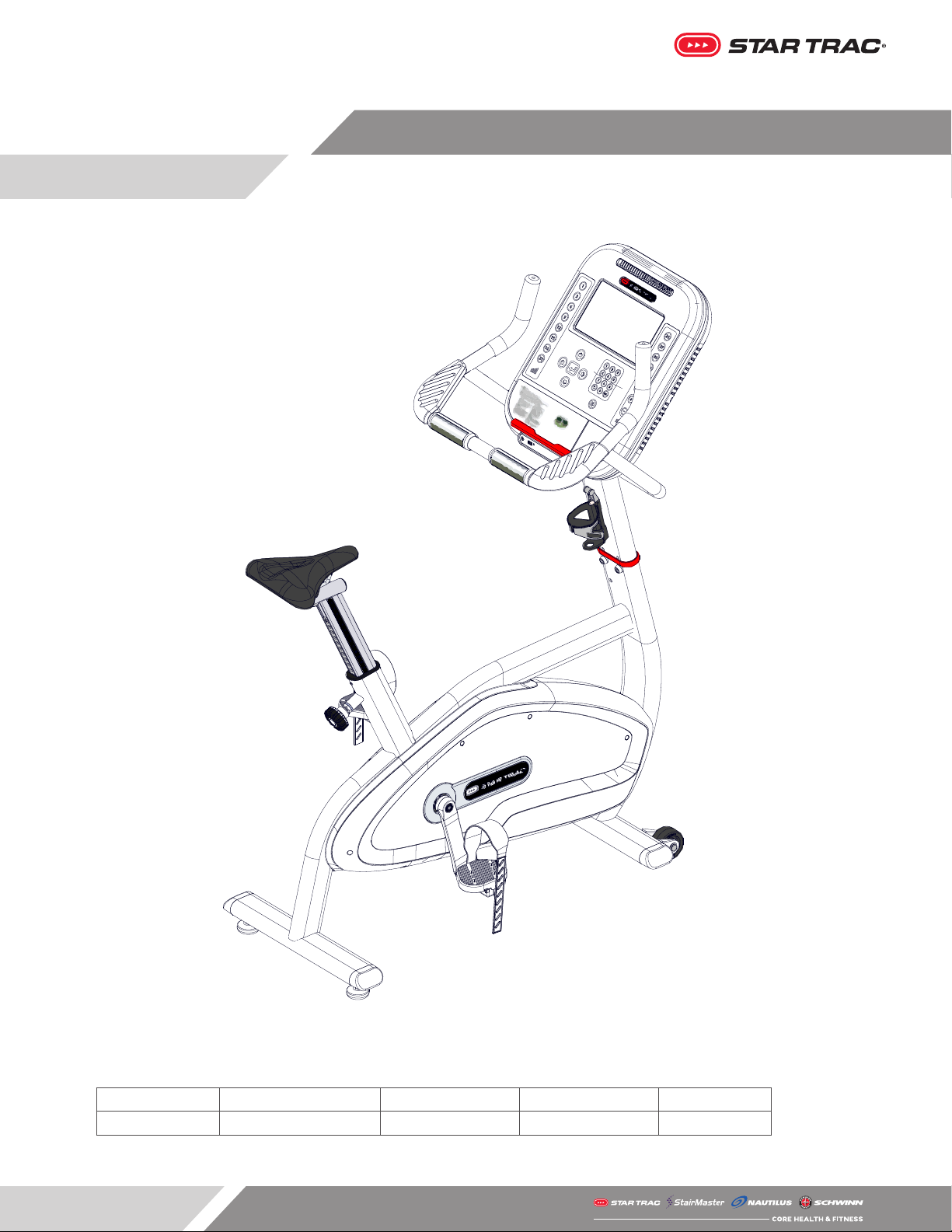
Core Health & Fitness Star Trac 4-UB User manual

ASSEMBLY
MANUAL
4-UB
Core Health & Fitness
Star Trac

Page 1
0.6m (23.6 in)
2.0m (78.8 in)
0.6m (23.6 in)
2.0m (78.8 in)
Required Clearance
1. Assemble and operate the machine on a solid
level surface. Position the machine with a
minimum of 19.7 inches (0.5 meters) of clearance
on each side to allow for ease of mounting and
dismounting. Allow for recommended minimum
of 19.7 inches (0.5 meters) of clearance in front
and behind the machine.
The actual area for access and passage shall be
the responsibility of the facility and should take
into account this training envelope, Americans
with Disabilities Act Accessibility Guidelines
(ADAAG) requirements and any required local
codes or regulations (www.access-board.gov/
ada).
2. Do not exceed the maximum allowable weight
limit of 450 lbs. / 204 kg.
3. This equipment it is not suitable for therapeutic
use.
4. Care should be used when mounting or
dismounting the equipment. Before mounting or
dismounting, move the pedal on the mounting or
dismounting side to its lowest position and bring
the machine to a complete stop.
5. If the power supply cord is damaged, it must be
replaced by the manufacturer, its service agent,
or similarly qualied persons in order to avoid
hazard.
6. The safety and integrity of this machine can only
be maintained when the equipment is regularly
examined for damage and wear and repaired.
It is the sole responsibility of the owner of this
equipment to ensure that regular maintenance
is performed. Worn or damaged parts must be
replaced immediately or the equipment removed
from service until the repair is made.
7. Caution: unit is heavy and requires two people for
assembly.
8. After assembly, a complete visual inspection,
and test of the features and functions of the
assembled bike must be made prior to use.
9. For complete instructions refer to the owner’s
manual.
IMPORTANT SAFETY INSTRUCTIONS
Before using this product, it is essential to read the ENTIRE Owner’s Manual and ALL installation
instructions. The Owner’s Manual describes equipment setup and instructs members on how to use
correctly and safely.
Read all warnings posted on the machine.
Health related injuries may result from incorrect or excessive use of exercise equipment. STAR TRAC
strongly recommends you to encourage your members to discuss their health program or tness
regimen with a health care professional, especially if you or they have not exercised for several years,
are over 35, or have known health conditions.
WARNING!

Page 2
9-3180-4UB-10IN 4-UB
Overall Weight Width Length Height User Weight
132 lbs (60 kg) 22.2 in (56.6 cm) 45.9 in (116.6 cm) 57.3 in (145.6 cm) 0-450 lbs (0-204 kgs)
PRODUCT SPOTLIGHT

Page 3
L
M
C
JO
K
B
D
N
I
H
E FA
G
L
M
C
JO
K
B
D
N
I
H
E FA
G
#PART #PART #PART
AConsole FSeat Pillar KFoot
BMast GSeat LTransport Wheel
CFrame HSeat Tube MGenerator
DHandlebar ISeat Adjustment NPedal Strap
EHeart Rate Grips JFlywheel OPedal
PART IDENTIFICATION

Page 4
Required Tools:
• 6mm Allen Key
• 4mm Allen Key
• #2 Phillips Screwdriver
• 19mm Open-ended Wrench
1. Route the wires through the mast beauty ring
(740-9313-XX), then up and out of the top of the
mast.
2. Once the wires are routed, insert the mast (718-
6006-XX) into the base frame.
3. Use a 6mm allen key to nish securing the mast
to the base frame using four (4) pieces each of
the M8 counter-bore washer (718-5693) and M8 x
20mm socket head cap screw (730-0889).
4. Use a 4mm allen key to secure the M8 x 40mm
set screw (740-4593) into the mast.

Page 5
5. Loosen the seat pop pin and pull outwards then
insert the seat post assembly (718-6016) into the
frame.
6. With the seat post sleeve ush into the frame, use
a #2 phillips screwdriver to install two (2) pieces
of the M4 x 16mm pan head screw (110-3164) to
secure the sleeve to the frame.
Seat Adjustment: To adjust the seat, turn the seat
adjustment pop pin counter-clockwise then pull
outwards. While pulling outwards on the pin, raise
or lower the seat to a comfortable position. Once
the seat is in the desired position, release the knob,
ensuring the pin locks into the seat post and turn
clockwise to tighten.
7. Unpack the console, console mounting screws,
and console install wiring instructions (620-8657)
from the console box.
8. Set the lower rear panel (020-7958) into place on
the mast, then install the back console shroud
(701-0344-XX).

Page 6
9. Use a #2 phillips screwdriver and attach the back
shroud of the console to the console mount
using eight (8) pieces each of the of the #8-18
x 3/4” pan head screw (110-3402) and M4 at
washer (120-3307).
10. Use a #2 phillips screwdriver to secure the back
shroud to the rear panel using four (4) of the #8-
18 x 3/8” pan head screws (731-0584).
11. See console install sheet (620-8657) in order to
connect the console to the base. 620-8657
12. After connecting the console to the base, use
a #2 phillips screwdriver to secure the console
front to the rear shroud using six (6) of the 8-18 x
3/4” pan head screws.

Page 7
13. Once the bike is fully assembled and is in it’s nal
position, adjust the rear leveling feet to ensure
the bike is level and stable, then use a 19mm
open-ended wrench to tighten the two (2) 1/2”
nuts to lock the feet.
14. Press 0+2+OK at the same time to access the
service menu.
15. Use the arrow keys to select “Maintenance Mode”
on the main service menu, then press
(enter).

Page 8
16. Use the arrow keys to select “MODEL” on the main
service menu, then press
(enter) to select the “4-Bike”.
See owner’s manual (620-8735) for more information.

Page 9
SUPPORT & SERVICE
• 24 hour self service access
• Real time communication
• Seamless Order Experience
• Intuitive user experience
• Mobile friendly technology
• Asset management
• Automated partner payment
• Seamless access to technical library
• Transparency on service performance
• Fast, reliable, quality service every time
CORE
CONNECT
Get world class support for all brands with our new support portal, Core
Connect. Get help with your general inquiries, warranty registration,
preventative maintenance, service requests and parts orders. You can
also make seamless service requests, get real time updates, manage your
assets and intuitively order parts for all brands direct from the site.
support.corehandf.com
Contact Information
CORE HEALTH & FITNESS
4400 NE 77th Avenue, Suite 300
Vancouver, WA 98662
Telephone: (888) 678-2476
http://www.corehandf.com
Customer Support
Contact your local distributor, or Core Health & Fitness
directly at: 1-800-503-1221
support@corehandf.com
Warranty information: https://corehandf.com/warranty

© 2019 CORE HEALTH & FITNESS, LLC PART NUMBER 620-8733, REV A
This manual suits for next models
1
Table of contents
Other Core Health & Fitness Exercise Bike manuals