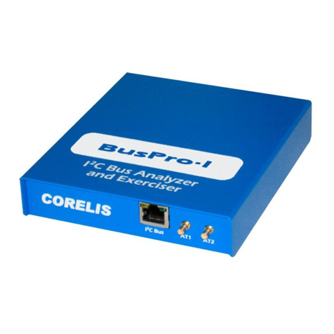
Corelis CAS-1000-I2C/E User manual


Preface i
Preface
Copyright © 2006-2017, Corelis Inc.
PRINTING HISTORY
Edition 1, February 2006
Edition 2, March 2006
Edition 3, May 2006
Edition 4, June 2006
Edition 5, November 2006
Edition 6, October 2007
Edition 7, July 2008
Edition 8, January 2009
Edition 9, January 2010
Edition 10, February 2011
Edition 11, October 2012
Edition 12, October 2013
Edition 13, October 2016
Edition 14, July 2017
GENERAL NOTICE
Information contained in this document is subject to change without notice. CORELIS shall not be liable
for errors contained herein for incidental or consequential damages in connection with the furnishing,
performance, or use of material contained in this manual.
This document contains proprietary information that is protected by copyright. All rights reserved. No part
of this document may be reproduced or translated to other languages without the prior written consent of
CORELIS. This manual is a CORELIS proprietary document and may not be transferred to another party
without the prior written permission of CORELIS.
CORELIS assumes no responsibility for the use of or reliability of its software on equipment that is not
furnished by CORELIS.
ENVIRONMENTAL NOTICE
This product must be disposed of in accordance with the WEEE directive.
TRADEMARK NOTICE
I2C Bus is a registered trademark of Philips Electronics N.V.
Pentium and SMBus are registered trademarks of Intel Corporation.
Windows is a registered trademark of Microsoft Corporation.
Other products and services named in this book are trademarks or registered trademarks of their
respective companies. All trademarks and registered trademarks in this book are the property of their
respective holders.

ii
PRODUCT WARRANTY AND SOFTWARE MAINTENANCE
For product warranty and software maintenance information, see the PRODUCT WARRANTY AND
SOFTWARE MAINTENANCE POLICY statement included with your product shipment.
EXCLUSIVE REMEDIES
THE REMEDIES CONTAINED HEREIN ARE THE CUSTOMER'S SOLE AND EXCLUSIVE REMEDIES.
CORELIS SHALL NOT BE LIABLE FOR ANY DIRECT, INDIRECT, SPECIAL, INCIDENTAL, OR
CONSEQUENTIAL DAMAGES, WHETHER BASED ON CONTRACT, TORT, OR ANY OTHER LEGAL
THEORY.
Product maintenance agreements and other customer assistance agreements are available for Corelis
products. For assistance, contact your nearest Corelis Sales and Service Office.
RETURN POLICY
No items returned to CORELIS for warranty, service, or any other reason shall be accepted unless first
authorized by CORELIS, either direct or through its authorized sales representatives. All returned items
must be shipped pre-paid and clearly display a Return Merchandise Authorization (RMA) number on the
shipping carton. Freight collect items will NOT be accepted.
Customers or authorized sales representatives must first contact CORELIS with notice of request for
return of merchandise. RMAs can only originate from CORELIS. If authorization is granted, an RMA
number will be forwarded to the customer either directly or through its authorized sales representative.
CONTACT INFORMATION
The latest news, tips and updates on the Corelis bus analyzer hardware and software products can be
found in the Corelis user forums. The forums are provided as a free service to our existing customers but
an individual user name and password is required. To request an account, please visit
forums.corelis.com/register.php
For sales inquiries, please contact sales@corelis.com.
For any support related questions, please enter a support request at www.corelis.com/support or email
support@corelis.com.
For more information about other products and services that Corelis offers, please visit www.corelis.com

iii
Table of Contents
Chapter 1 Product Overview ...................................................................................... 1
Introduction to I2C and SMBus.............................................................................................................. 1
Introduction to the CAS-1000-I2C™...................................................................................................... 2
Software Toolset..................................................................................................................................... 3
Hardware Features ................................................................................................................................. 4
Host Computer Requirements............................................................................................................... 6
Chapter 2 Installation.................................................................................................. 7
Installing the I2C Exerciser Application Software...............................................................................8
CAS-1000-I2C/E Hardware Installation ............................................................................................... 17
Chapter 3 Getting Started......................................................................................... 23
Overview ................................................................................................................................................ 23
Tutorial – Using Demo Mode ............................................................................................................... 23
Tutorial – Using Live Mode.................................................................................................................. 74
Chapter 4 Connecting to a Target............................................................................ 91
Connecting the I2C Signals.................................................................................................................. 91
Interface Setup...................................................................................................................................... 93
Chapter 5 Bus Traffic Monitor................................................................................ 103
Trace Listing ....................................................................................................................................... 104
Timing Field......................................................................................................................................... 107
Monitor Configurations ...................................................................................................................... 110
Monitor Preferences ........................................................................................................................... 117
Monitor Trigger ................................................................................................................................... 121
Monitor Window Reference ............................................................................................................... 134
Chapter 6 Interactive Debugger............................................................................. 150
Send Data ............................................................................................................................................ 151
Receive Data ....................................................................................................................................... 153
Debugger Script.................................................................................................................................. 155
Error Injection ..................................................................................................................................... 158
Debugger Options .............................................................................................................................. 160
Debugger Window Reference............................................................................................................ 162

iv
Chapter 7 Serial EEPROM Programmer ................................................................ 166
Programmer Operations .................................................................................................................... 167
Programmer Options.......................................................................................................................... 171
Programmer Window Reference ....................................................................................................... 172
Chapter 8 Configuration and Preferences ............................................................ 176
Configuration Manager ...................................................................................................................... 176
Preferences Dialog ............................................................................................................................. 193
Using Project Files ............................................................................................................................. 198
Calibration ........................................................................................................................................... 200
Chapter 9 Third Party Application Interface ......................................................... 203
Overview .............................................................................................................................................. 203
Dynamic Link Library (DLL)............................................................................................................... 204
General Calling Sequence ................................................................................................................. 205
Function Reference ............................................................................................................................ 206
Chapter 10 I2C Device Emulator............................................................................. 249
Emulation Manager Window.............................................................................................................. 251
Emulated Master Window .................................................................................................................. 257
Emulated Slave Window .................................................................................................................... 267
Emulated Slave Clock Stretching ..................................................................................................... 272
Chapter 11 Script-Driven Bus Tester..................................................................... 275
Test Window Reference ..................................................................................................................... 276
Chapter 12 Parameters Scope ............................................................................... 289
Parameter Measurements .................................................................................................................. 290
Waveform Display............................................................................................................................... 295
Parameters Scope Window Reference ............................................................................................. 297
Chapter 13 Scripting Language ............................................................................. 299
Overview .............................................................................................................................................. 299
The Essential Syntax Elements......................................................................................................... 300
Example Script.................................................................................................................................... 306
Built-in Functions: Summary ............................................................................................................ 308
Built-In Functions: Detailed Descriptions ........................................................................................ 312

v
Syntax Summary (Advanced Users Only)........................................................................................402
Built-In Script Editor ........................................................................................................................... 406
Chapter 14 Glitch Pattern Injection ....................................................................... 415
Overview .............................................................................................................................................. 415
Using the Glitch Pattern Editor .........................................................................................................416
Adding Glitch Patterns to Master and Slave Emulation .................................................................421
Appendix A CAS-1000-I2C Hardware Reference ................................................. 427
Hardware Specifications .................................................................................................................... 427
Electrical Specifications .................................................................................................................... 428

vi
List of Figures
Figure 1. I2C Bus Topology .......................................................................................................................... 1
Figure 2. Illustration of the CAS-1000-I2C ................................................................................................... 2
Figure 3. I2C Exerciser Installation Wizard .................................................................................................. 8
Figure 4. Windows Run Dialog..................................................................................................................... 9
Figure 5. License Agreement Screen........................................................................................................... 9
Figure 6. Customer Registration Screen .................................................................................................... 10
Figure 7. Destination Folder Screen .......................................................................................................... 11
Figure 8. Select Program Folder Screen.................................................................................................... 12
Figure 9. Completing the Installation Wizard Screen ................................................................................. 13
Figure 10. Windows 7 Security Warning Pop-up Window ......................................................................... 14
Figure 11. Windows XP Logo Test Warning Pop-up Window....................................................................14
Figure 12. Software Installation Button on the Windows XP Task Bar ......................................................15
Figure 13. Installation Completed Screen .................................................................................................. 16
Figure 14. Found New Hardware Wizard - Welcome Screen (Windows XP) ............................................17
Figure 15. Found New Hardware Wizard - Install Options (Windows XP)................................................. 18
Figure 16. Windows XP Logo Test Warning Pop-up Window....................................................................19
Figure 17. Found New Hardware Wizard – Installation Complete (Windows XP) .....................................20
Figure 18. Windows Device Manager (Windows XP) ................................................................................ 21
Figure 19. Initial I2C Exerciser Warning Message when CAS-1000-I2C is Not Initially Connected.......... 24
Figure 20. Tools Menu Demo Mode Selection........................................................................................... 25
Figure 21. Status Bar Indicating Demo Mode ............................................................................................ 25
Figure 22. Begin Monitor Data Collection .................................................................................................. 26
Figure 23. Demo Mode Reminder Pop-up Window ................................................................................... 26
Figure 24. Run Status Tab ......................................................................................................................... 27
Figure 25. Monitor Window Centered on Trigger Line ............................................................................... 28
Figure 26. Monitor Window Right-Click Pop-up Menu ............................................................................... 29
Figure 27. Monitor Window Trace List Positioned on Trigger Line ............................................................ 30
Figure 28. Monitor Window Right-Click Pop-up Menu Selecting Trigger Settings.....................................31
Figure 29. Configuration Manager Trigger Setup Screen ..........................................................................32
Figure 30. Monitor Window Trace List Column Headings..........................................................................33
Figure 31. I2C Exerciser Status Bar........................................................................................................... 33
Figure 32. Go to Start Tool Bar Button.......................................................................................................34
Figure 33. Monitor Window Trace List Showing Symbolic Address and Data Entries...............................35
Figure 34. Configuration Manager Symbols Definition Screen .................................................................. 36
Figure 35. Symbol Definition Dialog........................................................................................................... 37
Figure 36. Configuration Manager Symbols Definition Screen with DAC Symbol.....................................38
Figure 37. Monitor Window Trace List Showing New DAC Symbolic Address Entries .............................39
Figure 38. Monitor Window Trace List Data Byte Column Right-Click Pop-up Menu................................40
Figure 39. Monitor Window Trace List Data Column with Symbols Disabled............................................ 41
Figure 40. Monitor Window Trace List Data Byte Column Right-Click Pop-up Menu................................42
Figure 41. Monitor Window Trace List Data Column with Data Bytes in Binary Format............................ 42
Figure 42. Monitor Window Trace List Data Byte Column Right-Click Pop-up Menu................................43
Figure 43. Monitor Window Trace List in Compact Mode ..........................................................................44
Figure 44. Monitor Window Trace List in Compact Mode with Data Bytes Pop-up Window .....................45
Figure 45. Monitor Window Trace List I/O 2 Right-Click Pop-up Menu .....................................................46
Figure 46. Dragging Monitor Window Trace List I/O 1 Column Heading................................................... 46
Figure 47. Monitor Window Trace List with Rearranged I/O Columns....................................................... 47
Figure 48. Trace Layout Dialog .................................................................................................................. 48

vii
Figure 49. Monitor Window Timing Display................................................................................................ 49
Figure 50. Monitor Window Trace List Positioned on Cursor A Line ......................................................... 50
Figure 51. Monitor Window Trace List Positioned on Cursor B Line ......................................................... 51
Figure 52. Monitor Window Timing Display Showing Edges Zoomed in at Line 100 ................................52
Figure 53. Monitor Window Timing Display Measuring the Time Between Cursors A & B ....................... 53
Figure 54. Go to Start Tool Bar Button.......................................................................................................54
Figure 55. Find Tool Bar Button ................................................................................................................. 55
Figure 56. Find Dialog ................................................................................................................................ 55
Figure 57. Find a Data Value of 2E............................................................................................................ 57
Figure 58. Monitor Window Trace List Showing Find 2E Data Result .......................................................58
Figure 59. Find a Data Value of 72 ............................................................................................................59
Figure 60. Clear Tagged Rows Prompt...................................................................................................... 59
Figure 61. Matched Transactions Prompt .................................................................................................. 60
Figure 62. Monitor Window Trace List Showing Find 72 Data Result ....................................................... 60
Figure 63. Go to Tagged Row Tool Bar Button.......................................................................................... 61
Figure 64. Monitor Window Trace List Showing the Second Find 72 Data Result ....................................61
Figure 65. Monitor Colors Preferences Screen.......................................................................................... 62
Figure 66. Monitor Colors Preferences Screen Changing Cursor A Background Color ............................63
Figure 67. Monitor Window with Updated Cursor A Colors ....................................................................... 64
Figure 68. Monitor Window with Updated Cursor A Colors ....................................................................... 65
Figure 69. Monitor Window with Alternating Row Colors........................................................................... 66
Figure 70. Monitor Window Trace List with the Trigger Line Centered......................................................67
Figure 71. Monitor Options Preferences Screen........................................................................................ 68
Figure 72. Monitor Window Trace List with Trigger at Line Zero Numbering ............................................69
Figure 73. Monitor Window Trace List with Trigger is Time Zero Timestamps.......................................... 70
Figure 74. Monitor Window Trace List with Relative Timestamps ............................................................. 71
Figure 75. Monitor Window Trace List Showing Addresses in FE mode...................................................72
Figure 76. Monitor Window Trace List Showing Addresses in 7F mode ...................................................73
Figure 77. Tools Menu Deselect Demo Mode............................................................................................ 74
Figure 78. Status Bar Indicating Live Data Mode ...................................................................................... 74
Figure 79. Analyzer Supplied Mode Prompt .............................................................................................. 75
Figure 80. Debugger Window .................................................................................................................... 76
Figure 81. Byte Sent From the Debugger .................................................................................................. 77
Figure 82. Receive Three Bytes in the Debugger ...................................................................................... 78
Figure 83. Capture of Debugger Send ....................................................................................................... 79
Figure 84. Tutorial Script Loaded Into Debugger .......................................................................................80
Figure 85. Capture of Debugger Script ...................................................................................................... 81
Figure 86. Set Discrete I/O Modes ............................................................................................................. 82
Figure 87. Debugger Discrete I/O Script .................................................................................................... 83
Figure 88. Monitor Debugger Discrete I/O Manipulation............................................................................83
Figure 89. Debugger Close ........................................................................................................................ 84
Figure 90. SMBus Raw Data...................................................................................................................... 85
Figure 91. SMBus Pane Before Associating Decoder File ........................................................................ 86
Figure 92. SMBus Decoder File Dialog with TC74 Information .................................................................87
Figure 93. Switch to SMBus Mode ............................................................................................................. 88
Figure 94. SMBus Decoded Data .............................................................................................................. 88
Figure 95. Decoded SMBus Message ToolTip .......................................................................................... 89
Figure 96. SMBus Data Window ................................................................................................................ 89
Figure 97. RJ45 Connector Pin Numbering ............................................................................................... 92
Figure 98. Configuration Manager ............................................................................................................. 94
Figure 99. Analyzer Supplied Voltage Prompt ...........................................................................................95
Figure 100. Configuration Manager Analyzer Supplied .............................................................................96
Figure 101. Configuration Manager Settings Pane .................................................................................... 98
Figure 102. Bus Electrical Features ........................................................................................................... 99
Figure 103. Bus Drive and Monitoring Features ...................................................................................... 100

viii
Figure 104. Input/Output Signals ............................................................................................................. 101
Figure 105. Monitor Buffer Options .......................................................................................................... 102
Figure 106. Monitor Window .................................................................................................................... 103
Figure 107. Monitor Trace Listing ............................................................................................................ 104
Figure 108. Monitor Timing Field ............................................................................................................. 107
Figure 109. Timing Field Popup Menu ..................................................................................................... 109
Figure 110. Filters Pane ........................................................................................................................... 111
Figure 111. Filter Definition Dialog (similar to Edit).................................................................................. 112
Figure 112. Symbols Pane ....................................................................................................................... 113
Figure 113. Symbol Definition Dialog....................................................................................................... 114
Figure 114. SMBus Pane ......................................................................................................................... 115
Figure 115. SMBus Decoder File Dialog .................................................................................................. 116
Figure 116. Monitor Colors Pane ............................................................................................................. 117
Figure 117. Monitor Options Pane ........................................................................................................... 119
Figure 118. Formats Pane........................................................................................................................ 120
Figure 119. Trigger Tab on Monitor Tools Dialog ....................................................................................121
Figure 120. Trigger on Single Event ........................................................................................................ 125
Figure 121. Trigger on Repeated Single Event........................................................................................ 126
Figure 122. Trigger on Sequence of Multiple Events ...............................................................................127
Figure 123. Trigger on Consecutive Sequence of Events ....................................................................... 128
Figure 124. Trigger Dialog........................................................................................................................ 129
Figure 125. Context Popup Menu on Trigger Definition Tree ..................................................................130
Figure 126. Create New Trigger Dialog ................................................................................................... 131
Figure 127. Active Trigger Operation Status............................................................................................ 133
Figure 128. I2C Exerciser Monitor Window Layout.................................................................................. 134
Figure 129. Monitor File Menu ................................................................................................................. 135
Figure 130. Monitor Trace Menu .............................................................................................................. 136
Figure 131. Trace | Execute Submenu .................................................................................................... 137
Figure 132. Run Status Tab on Monitor Tools Window ........................................................................... 138
Figure 133. Trace | Go To Submenu .......................................................................................................139
Figure 134. Trace | View Submenu.......................................................................................................... 140
Figure 135. Monitor Find Dialog – Regular .............................................................................................. 141
Figure 136. Monitor Find Dialog – Compact ............................................................................................ 141
Figure 137. Trace Layout Dialog .............................................................................................................. 143
Figure 138. Tools Menu ........................................................................................................................... 144
Figure 139. Monitor Window Menu .......................................................................................................... 146
Figure 140. Monitor Help Menu................................................................................................................ 146
Figure 141. Monitor Tool Bar.................................................................................................................... 147
Figure 142. Debugger Window ................................................................................................................ 150
Figure 143. Debugger Send Controls ...................................................................................................... 151
Figure 144. Debugger Receive Controls.................................................................................................. 153
Figure 145. Debugger Options Pane ....................................................................................................... 160
Figure 146. I2C Exerciser Debugger Window Layout .............................................................................. 162
Figure 147. Debugger File Menu ............................................................................................................. 163
Figure 148. Debugger Tool Bar................................................................................................................ 164
Figure 149. Programmer Window ............................................................................................................ 167
Figure 150. Programmer Read Window................................................................................................... 169
Figure 151. Programming Progress Window ........................................................................................... 170
Figure 152. Verifying Progress Window................................................................................................... 170
Figure 153. Erasing Progress Window..................................................................................................... 170
Figure 154. Programmer Options Pane ................................................................................................... 171
Figure 155. I2C Exerciser Programmer Window...................................................................................... 172
Figure 156. Programmer File Menu ......................................................................................................... 173
Figure 157. Programmer Tool Bar ........................................................................................................... 174
Figure 158. Configuration Manager Dialog Panes (Settings selected)....................................................177

ix
Figure 159. Filters Pane ........................................................................................................................... 179
Figure 160. Filter Definition Dialog (similar to Edit).................................................................................. 180
Figure 161. Symbols Pane ....................................................................................................................... 181
Figure 162. Symbol Definition Dialog....................................................................................................... 182
Figure 163. SMBus Pane ......................................................................................................................... 183
Figure 164. SMBus Decoder File Dialog .................................................................................................. 184
Figure 165. Settings Pane........................................................................................................................ 185
Figure 166. Files Pane ............................................................................................................................. 189
Figure 167. Target Slaves Pane .............................................................................................................. 190
Figure 168. Timing Skew Pane ................................................................................................................ 192
Figure 169. Monitor Colors Pane ............................................................................................................. 193
Figure 170. Monitor Options Pane ........................................................................................................... 194
Figure 171. Debugger Options Pane ....................................................................................................... 195
Figure 172. Programmer Options Pane ................................................................................................... 196
Figure 173. Formats Pane........................................................................................................................ 197
Figure 174. Title Bar for a New Project ....................................................................................................198
Figure 175. Title Bar for a Saved Project ................................................................................................. 199
Figure 176. File Menu MRU Project List .................................................................................................. 199
Figure 177. Calibration Prompt ................................................................................................................ 200
Figure 178. Calibration Warning .............................................................................................................. 200
Figure 179. Calibration Status.................................................................................................................. 201
Figure 180. Calibration Complete ............................................................................................................ 201
Figure 181. Emulation Manager Window ................................................................................................. 251
Figure 182. Emulator Manager Window................................................................................................... 252
Figure 183. Add Emulated Device Dialog ................................................................................................ 254
Figure 184. Emulator Execute Menu........................................................................................................ 255
Figure 185. Emulator Tool Bar ................................................................................................................. 256
Figure 186. Emulated Master Window ..................................................................................................... 257
Figure 187. Emulated Master Source Popup Menu ................................................................................. 259
Figure 188. Emulated Master File Menu .................................................................................................. 261
Figure 189. Emulated Master Edit Menu.................................................................................................. 262
Figure 190. Emulated Master Execute Menu........................................................................................... 263
Figure 191. Emulated Master Breakpoint Menu....................................................................................... 264
Figure 192. Emulated Master Tool Bar .................................................................................................... 265
Figure 193. Emulated Slave Window ....................................................................................................... 267
Figure 194. Emulated Slave File Menu .................................................................................................... 268
Figure 195. Emulated Slave Edit Menu.................................................................................................... 269
Figure 196. Emulated Slave Tool Bar ...................................................................................................... 270
Figure 197. Configuring Emulated Slave Device .....................................................................................273
Figure 198. Clock Stretched on ACK Bit .................................................................................................. 273
Figure 199. Test Window ......................................................................................................................... 276
Figure 200. Test Window ......................................................................................................................... 277
Figure 201. Test Source Popup Menu ..................................................................................................... 280
Figure 202. Test File Menu ...................................................................................................................... 282
Figure 203. Test Edit Menu ......................................................................................................................283
Figure 204. Test Execute Menu ............................................................................................................... 284
Figure 205. Test Breakpoint Menu ...........................................................................................................284
Figure 206. TestTool Bar.......................................................................................................................... 286
Figure 207. Parameters Scope Window .................................................................................................. 289
Figure 208. Parameters Scope Measurement Controls........................................................................... 290
Figure 209. Parameter Specification File Example .................................................................................. 294
Figure 210. Parameters Scope Waveform Controls ................................................................................ 295
Figure 211. Editor Window ....................................................................................................................... 407
Figure 212. Editor Popup Menu ............................................................................................................... 408
Figure 213. I2C Exerciser Editor Window Layout .................................................................................... 409

x
Figure 214. Editor File Menu .................................................................................................................... 410
Figure 215. Editor Edit Menu ................................................................................................................... 411
Figure 216. Editor Tool Bar ...................................................................................................................... 413
Figure 217. Glitch Pattern Editor Window ................................................................................................ 416
Figure 218. Glitch Injection Trigger Conditions ........................................................................................ 417
Figure 219. Default Glitch Pattern Setting................................................................................................ 418
Figure 220. SDA Low Glitch Injected by Data / SDA / Rising-edge Triggering Condition .......................418
Figure 221. SDA Low Glitch Waveform ................................................................................................... 419
Figure 222. Glitch Pattern Editor File Menu ............................................................................................. 420

xi
List of Tables
Table 1. Optional Interface Cables ............................................................................................................... 7
Table 2. Flying Leads Serial Bus Connector Pin Assignments .................................................................. 91
Table 3. 4-Pin Crimp Cable Pin Assignments ............................................................................................ 92
Table 4. Summary of available Trigger Components ............................................................................... 122
Table 5. Monitor Window Layout .............................................................................................................. 134
Table 6. Monitor Tool Bar Functions ........................................................................................................ 148
Table 7. Debugger Script Keywords ......................................................................................................... 156
Table 8. Debugger Error Injection Keywords............................................................................................159
Table 9. Debugger Window Layout .......................................................................................................... 162
Table 10. Debugger Tool Bar Functions................................................................................................... 164
Table 11. Programmer Function Descriptions .......................................................................................... 168
Table 12. Programmer Read Contents Window Function Descriptions...................................................169
Table 13. Programmer Window Areas ..................................................................................................... 172
Table 14. Programmer Tool Bar Functions .............................................................................................. 174
Table 15. Configuration Manager Panes.................................................................................................. 178
Table 16. DLL Components...................................................................................................................... 204
Table 17. I2C DLL Functions .................................................................................................................... 207
Table 18. List of I2C Bus Measurement Parameters ................................................................................ 219
Table 19. Emulation Manager Areas ........................................................................................................ 251
Table 20. Emulator Tool Bar Functions .................................................................................................... 256
Table 21. Emulated Master Tool Bar Functions ....................................................................................... 266
Table 22. Emulated Slave Tool Bar Functions ......................................................................................... 271
Table 23.Test Window Areas.................................................................................................................... 276
Table 24. Test Tool Bar Functions ........................................................................................................... 287
Table 25. Built-In Scripting Functions....................................................................................................... 311
Table 26. Editor Window Areas ................................................................................................................ 409
Table 27. Editor Tool Bar Icon Descriptions ............................................................................................. 414


Introduction xiii
Introduction
What this User’s Manual Covers
This User’s Manual was designed to make using your CAS-1000-I2C™ analyzer and its software easier
and more efficient. The manual contains easy to navigate tutorials and reference information that are
presented in a logical progression.
The following briefly summarizes each chapter:
Chapter 1: Product Overview
This chapter provides you with an introduction to the I2C bus and SMBus as well as a description of the
CAS-1000-I2C analyzer and software application features.
Chapter 2: Installation
In this chapter you will learn how to install the I2C Exerciser software and the CAS-1000-I2C hardware.
Chapter 3: Getting Started
This chapter introduces you to the basic usage of the CAS-1000-I2C for monitoring and generating bus
traffic, writing debug scripts, and working with EEPROM devices. Although it is possible to explore the
capabilities of the CAS-1000-I2C on your own, working through this chapter will provide you with an
immediate feel for its ease of use and core functionality.
Chapter 4: Connecting to a Target
This chapter provides you with instructions on how to hook up the CAS-1000-I2C to a target board and
describes the initial software settings that you should be aware of to have the CAS-1000-I2C working
properly.
Chapter 5: Bus Traffic Monitor
This chapter describes the features of the Monitor window which is used to collect and analyze traffic
from the target I2C bus.
Chapter 6: Interactive Debugger
This chapter describes the features of the Debugger which is used to manually generate traffic and
interact with the target I2C bus.
Chapter 7: Serial EEPROM Programmer
This chapter describes the features of the Programmer which is used to read and write the content of
EEPROM memory devices on the target I2C bus.

xiv Introduction
Chapter 8: Configuration and Preferences
This chapter describes all of the various project options and settings that can be found in the
Configuration Manager and Preferences dialogs.
Chapter 9: Third Party Application Interface
This chapter provides a reference on all of the function calls available for use in third party software
applications that control the CAS-1000-I2C analyzer through the provided dynamic link library (DLL).
Chapter 10: I2CDevice Emulator
This chapter describes the features of the Emulator which is used to emulate master and slave devices
on the target I2C bus.
Chapter 11: Script-Driven Bus Tester
This chapter describes the features of the Test tool which is used to execute test scripts that perform a
sequence of measurements and tests of the target I2C bus.
Chapter 12: Parameters Scope
This chapter describes the features of the Parameters Scope which is used to measure the electrical and
timing characteristics of the target I2C bus.
Chapter 13: Scripting Language
This chapter provides a reference on the usage and syntax elements of the I2C Exerciser’s scripting
language which is used in automated bus testing and device emulation.
Chapter 14: Glitch Pattern Injection
This chapter describes the features of the Glitch Pattern Injection which is used to inject glitches into the
target I2C bus.
Appendix A: CAS-1000-I2C Hardware Reference
This appendix presents a table comparing the features in different versions of Corelis bus analyzers as
well as the physical and electrical specifications for the CAS-1000-I2C hardware.

Product Overview 1
Chapter 1
Product Overview
CAS-1000-I2C/E™ Bus Analyzer and I2C Exerciser product overview
Introduction to I2C and SMBus
The I2C bus was developed by Philips for basic communication between devices. It has since evolved,
increasing in performance and finding many new applications including data transfer and system-level
command-and-control.
As shown in Figure 1, the physical I2C bus consists of two bidirectional open-drain signals and a common
ground. The two active signals on the bus consist of a serial data line (SDA) and a serial clock line (SCL),
each requiring a system voltage reference through a pull-up resistor. Every device connected to the bus
is software addressable by a unique address and masters can operate as master-transmitters or as
master-receivers. The I2C bus supports a multi-master bus methodology including collision detection and
arbitration to avoid data corruption if two or more masters simultaneously initiate data transfer. Serial, 8-
bit oriented bidirectional data transfers can be made at up to 100 Kbit/s in the Standard mode or up to
400 Kbit/s in the Fast mode.
Figure 1. I2C Bus Topology
The System Management Bus, or SMBus, was defined by Intel® Corporation in 1995 and is based on the
I2C bus architecture. It is used in personal computers and servers for low-speed system management
communications.
SMBus is a two-wire interface through which simple system and power management related chips can
communicate with the rest of the system. A system using SMBus as a control bus for these system and
power management related tasks pass messages to and from devices by addressed transfers, enabling
moderate transfer rates using minimal board resources. With System Management Bus, for example, a

2Product Overview
device can provide manufacturer information, tell the system what its model/part number is, save its state
for a suspend event, report different types of errors, accept control parameters, and return its status. The
SMBus may share the same host device and physical bus with standard I2C components. Intel originally
conceived the SMBus as the communication bus to accommodate Smart Batteries and other system and
power management components.
Introduction to the CAS-1000-I2C™
The Corelis CAS-1000-I2C is an I2C-bus/SMBus analyzer, exerciser, programmer, and tester. This
advanced instrument is used to:
Monitor and log I2C bus traffic in real-time
Generate traffic to exercise the bus and communicate with its slave components
Program and read in-system EEPROMs
Emulate I2C master and slave devices that are not yet physically connected to the bus (/E version
only)
Measure and test bus performance and characteristics (/E version only)
Because of its rich feature set and ease-of-use, the CAS-1000-I2C can be used in a variety of
applications, such as product development, troubleshooting, validation, system integration, production,
and field testing.
The CAS-1000-I2C pod, shown in Figure 2, connects to the PC via a high-speed USB 2.0 port and can
operate either with the provided I2C Exerciser software application, or using the included API of C/C++
library function calls from third party software applications such as National Instruments’ LabWindows/CVI
and LabVIEW, or custom user-developed software.
The CAS-1000-I2C/E also includes a JTAG controller that, when used with the optional Corelis
ScanExpress software, can perform boundary-scan interconnect testing and in-system programming of
flash memories and CPLDs. This JTAG testing capability is complementary to the I2C bus testing features
of the CAS-1000-I2C/E and greatly enhances target visibility control and testing access.
Figure 2. Illustration of the CAS-1000-I2C

Product Overview 3
Software Toolset
Monitor
Using the Monitor tool, the CAS-1000-I2C listens and records all I2C bus traffic while displaying it as
both state and timing information. Transactions can be examined and stored to files and later
retrieved for review. Monitor features include message filtering, symbolic translation of numeric
values, and event triggering. The CAS-1000-I2C continually verifies compliance to the bus protocol
and flags errors when it detects a protocol violation. Concurrent with the bus transaction state listings,
a timing display for both the SCL and SDA signals is depicted showing the edge transition history.
Debugger
Using the Debugger tool, the CAS-1000-I2C can be utilized to send and receive individual messages
on the I2C bus. Looping is supported for repeating I/O patterns to facilitate external signal
observation. Storing and restoring files allows saving of received data for post-analysis and reuse of
previously sent message scripts. A callable API library distributed as a Windows DLL further enables
access to the I2C bus from 3rd-party applications outside of the I2C Exerciser GUI.
Programmer
Using the Programmer tool, the CAS-1000-I2C can be utilized to perform high speed programming of
I2C-compatible serial EEPROM memory devices, with a user interface similar to the Corelis
ScanExpress Programmer boundary-scan in-system programming product. Devices can be
programmed in-system and at maximum programming speed, which is typically within several
seconds depending on the memory size. The Programmer provides options to Erase, Program,
Verify, and Read target EEPROM memory. The content of the EEPROM memory device can be
saved to a file in a supported file format including Motorola S-Record, Intel Hex, and a hex-text file
format.
Emulator
Using the Emulator tool, the CAS-1000-I2C/E can be configured to emulate a master or slave device
on the target I2C bus. The behavior of the emulated device is controlled using a sophisticated
scripting language that has a simplified C-language syntax. When emulating a slave, blocks of data
are defined that will be used in responding to any master transactions. When emulating a master, the
functionality of the Debugger tool is taken to the next level, adding conditional branching and
schedule control that enables a comprehensive bus and target exercising sequence, ranging from
simple target initialization to complex behavioral stimulation, stressing, and evaluation.
Test
Using the Test tool, the scripting features available in the Emulator tool are enhanced with the ability
to measure and compare target I2C bus electrical and timing parameters as well as the faculty to
manipulate the GUI elements of the Test window. Scripts run with the Test tool manipulate and
evaluate the behavior of the target bus and make a “go” or “no-go” decision on whether performance
is within a desired specification, reporting back the status and results via the Test window controls.
Parameters Scope
Using the Parameters Scope tool, the CAS-1000-I2C/E can be utilized to quickly measure and return
the basic electrical and timing parameters of the target I2C bus without setting up the advanced
scripting functions of the Test tool. It can gather master-specific and slave-specific parameters, such
as signal timing characteristics, and also system-wide parameters, such as bus voltage, pull-up
resistance, and capacitance. Each measurement is compared to maximum and minimum values
loaded from a specification file and the resulting pass or fail status is shown with the measurement.
The Parameters Scope provides the additional ability to display a graph of captured signal edge
transition data and a trigger can be set to capture a particular I2C bus signal’s rising or falling edge.

4Product Overview
Hardware Features
The main hardware features of the CAS-1000-I2C/E are described in the following sections.
I2C Speed Support
The CAS-1000-I2C operates using the Standard/Fast-mode/Fast-mode Plus protocol over its entire
performance range for both monitoring and driving the bus (up to 5 MHz as a master, 1.9 MHz as a
slave). The High-speed mode (Hs-mode) is supported for monitoring only. Additionally, an accelerated
rising slope control feature is included to facilitate the driving of higher capacitance targets at high clock
rates.
USB Port Host Interface
The CAS-1000-I2C uses a high-speed USB 2.0 interface for easy connection to a PC. The host PC
supplies operating power to the unit and the hot-plug feature of the USB standard is fully supported. You
simply plug the CAS-1000-I2C into a PC USB 2.0 socket and it will be automatically detected, configured,
and then ready to go.
A USB 2.0 port on the host computer is required for optimal performance. The CAS-1000-I2C does not
support USB 1.1 ports.
Software Programmable Voltage Levels and Pull-Up Resistors
The I2C bus reference voltage can be programmed as target-driven (Target Supplied mode) through its
own pull-ups or as driven from the CAS-1000-I2C (Analyzer Supplied mode) through instrument pull-ups.
When the CAS-1000-I2C is programmed to source this reference level (for both SCL and SDA signals),
the voltage can be set in 100 mV steps from 0.8V to 5.0V. In this case, the target pull-ups should be
removed to prevent contention with the analyzer.
In addition, for the Analyzer Supplied mode reference voltage, you can select one of a set of pull-up
resistors with the same value for both bus signals. The resistor values can be set from about 250 to 50K
ohms in varying increments.
The TTL output signal level of the set of discrete I/O and trigger lines is programmable from 1.25V to 3.3V
in steps of 50 mV.
Furthermore, sensed bus signal high and low threshold levels can each be adjusted, supporting the bus
hysteresis requirement. Default software-determined values are provided automatically with user override
capability.
Table of contents
Other Corelis Measuring Instrument manuals