Corken Coro-Flo 9 Series Instruction manual

ORIGINAL INSTRUCTIONS IF101K
Warning: (1) Periodic inspection and maintenance of Corken products is essential. (2) Inspection, maintenance and installation of Corken products must be made only by
experienced, trained and qualified personnel. (3) Maintenance, use and installation of Corken products must comply with Corken instructions, applicable laws and safety
standards (such as NFPA Pamphlet 58 for LP-Gas and ANSI K61.1-1972 for Anhydrous Ammonia). (4) Transfer of toxic, dangerous, flammable or explosive substances
using Corken products is at user’s risk and equipment should be operated only by qualified personnel according to applicable laws and safety standards.
Installation, Operation
& Maintenance Manual
Regenerative Turbine Coro-Flo®Pumps
Models C, CF, DL, DLF, DS, DSF, F, and FF
Pump Sizes 9, 10, 12, 13, 14, and 15
C-Model
DS-/DL-Model
F-Model
C-Model
Solutions beyond products...
www.northridgepumps.com

Warning
Install, use and maintain this equipment according to Corken, Inc. instructions and all applicable federal, state, local
laws and codes, and NFPA Pamphlet 58 for LP-Gas or ANSI K61.1-1989 for Anhydrous Ammonia. Periodic inspection
and maintenance is essential.
Corken One Year Limited Warranty
Corken, Inc. warrants that its products will be free from defects in material and workmanship for a period of one year
from date of installation, provided that the warranty shall not extend beyond twenty-four (24) months from the date of
shipment from Corken. Corken products which fail within the warranty period due to defects in material or workmanship
will be repaired or replaced at Corken’s option, when returned freight prepaid to: Corken, Inc., 3805 N.W. 36th Street,
Oklahoma City, Oklahoma 73112.
Parts subject to wear or abuse are not covered by this limited warranty. Also, equipment, parts and accessories not
manufactured by Corken but furnished with Corken products are not covered by this limited warranty and purchaser
must look to the original manufacturer’s warranty, if any. This limited warranty is void if the Corken product has been
altered or repaired without the consent of Corken.
ALL IMPLIED WARRANTIES, INCLUDING ANY IMPLIED WARRANTY OF MERCHANTABILITY OR FITNESS
FOR A PARTICULAR PURPOSE, ARE EXPRESSLY NEGATED TO THE EXTENT PERMITTED BY LAW AND
SHALL IN NO EVENT EXTEND BEYOND THE EXPRESSED WARRANTY PERIOD.
Corken disclaims any liability for consequential damages due to breach of any written or implied warranty on Corken
products. Transfer of toxic, dangerous, flammable or explosive substances using Corken products is at the user’s risk.
Such substances should be handled by experienced, trained personnel in compliance with governmental and
industrial safety standards.
Contacting the Factory
For your convenience, the model number and serial number are given on the compressor nameplate. Space is
provided below for you to keep a written record of this information.
Always include the model number and serial number when ordering parts.
Model No.
Serial No.
Date Purchased
Date Installed
Purchased From
Installed By
2
www.northridgepumps.com

Table of Contents
PRINCIPLES OF A REGENERATIVE TURBINE CORO-FLO®PUMP ....................................4
EXCLUSIVE FEATURES OF YOUR CORO-FLO®PUMP ..............................................4
CHAPTER 1—INSTALLATION OF YOUR CORKEN CORO-FLO®PUMP .................................5
1.1 Location .................................................................................5
1.2 The Inlet Should Include the Following .........................................................5
1.3 The Outlet Piping Should Include the Following ..................................................5
1.4 The Bypass System Must Include the Following ..................................................5
1.5 Pump Foundation—F-Models ................................................................6
1.6 Level Base ...............................................................................6
1.7 Coupling Alignment—F-Models ...............................................................6
1.8 Back-up Wrench...........................................................................6
1.9 Driver Installation ..........................................................................6
1.10 Wire Sizing Chart—C-Models ...............................................................7
1.11 Wire Sizing Chart—DL-, DLF-, DS-, DSF-, F-, and FF-Models.......................................8
CHAPTER 2—OPERATION OF YOUR CORO-FLO®PUMP............................................8
2.1 Filling New Cylinders and Tanks ..............................................................8
2.2 Pumping From Underground Tanks ............................................................8
2.3 Installation Design Criteria For Underground Tank Applications ......................................9
CHAPTER 3—PREVENTATIVE MAINTENANCE FOR YOUR CORO-FLO®PUMP .........................9
CHAPTER 4—REPAIR SERVICE ON YOUR CORO-FLO®PUMP .......................................9
CHAPTER 5—CORO-FLO®SEAL REPLACEMENT INSTRUCTION....................................10
APPENDICES
A. Model Number Identification Code and Available Options ..........................................18
B. Specifications ............................................................................21
C. Performance .............................................................................23
D. Outline Dimensions ........................................................................26
E. Parts Details .............................................................................35
F. Troubleshooting Guide ......................................................................43
G. Extended Storage .........................................................................44
H. Aboveground Installation/Piping Instructions ....................................................45
I. Underground Installation/Piping Instructions .....................................................47
3
www.northridgepumps.com

Principles of a Regenerative
Turbine Coro-Flo
®
Pump
The Corken Coro-Flo®Pump is a special type of pump
known as a turbine or regenerative pump. The liquid flows
into the inlet nozzle and into the passageway on each side
of an impeller (the rotating element) and is recirculated
constantly between the vanes or teeth of the impeller and
this passageway as the impeller rotates. The fluid makes
a complete revolution in the pump case and is diverted
out the outlet nozzle. The horsepower required to drive
the pump increases as the differential pressure increases,
but the capacity decreases at the same time. Differential
pressure is the difference between the pressure at the
inlet of the pump and at the outlet of the pump.
The impeller is the only moving part and has no contact
with the casing. Consequently, practically no wear
occurs to the impeller, even when pumping volatile
liquids such as LP-gas or ammonia which have little
lubricating qualities.
Exclusive Features of Your
Coro-Flo
®
Pump
The pumping of volatile liquids is one of the most difficult
of all pumping jobs. Unlike other pumping operations,
more attention must be given to the design, manufacture
installation, and operation of the pump.
In addition to being a pump type especially suited for
handling volatile liquids, your Coro-Flo® pump has a
number of features which help to make it more easily
operated and maintained.
• Available with three mounting options: close-coupled
(C-model), frame-mounted (F-model), and direct-
mounted (D-model).
• Underwriters’ Laboratories, Inc. have tested and
inspected the C-model pumps and have listed them for
use in the handling of LP-gas and ammonia fluids. The
nameplate on the pump shows the UL label.
• Ductile iron, the metal with the strength of steel, has
been used in the manufacture of this pump for parts
under pressure of the liquid.
• The impeller floats on a shaft and may be replaced
easily without disturbing the piping or driver by simply
removing the cover. No special tools are needed.
• The mechanical seal assembly may be replaced
easily by removing the cover and the impeller and
without disturbing the piping or driver. No special
tools are needed.
• The pump nozzles may be rotated into four different
positions, 90 degrees apart, if desired.
• A bypass connection, 3/4" pipe thread, has been
located on the outlet nozzle to make the piping of the
pump more simple.
• Pressure gauge connections, 1/4" pipe thread, have
been located on the outlet nozzle.
• Motors on models C10, C12, C13 and C14 are explosion-
proof, Class I, Group D - UL and CSA listed. The C10,
C12 and C13 motors are all single phase. 60 Hertz
(50/60 Hertz on C13 only), 3450 RPM, 115/230 volt.
The C14 motor is three-phase, 60 Hertz, 3450 RPM,
230/460 bolts. Corken provides two manual motor
starters for models C10, C12 and C13. One is motor-
mounted and the other is wall-mounted. These motors
(after pump serial number TS185540) are provided with
a conduit seal in the 3/4" NPT rigid galvanized steel
nipple, fulfilling the 1996 requirement of NFPA 70-NEC,
paragraphs 501.5.a.1 & 3. Separate motor starters with
overload protection must be provided for the model C14
and all F series pumps.
4
www.northridgepumps.com

1.1 Location
The installation of a Coro-Flo®pump is a simple matter.
However, in order for the pump to deliver the performance
you expect, the principles discussed in this book must
be followed exactly. The piping instructions in Appendix
H illustrate methods proved by hundreds of installations.
Your own needs may require some slight variations, but
they must be slight, and no compromise made.
If it is desirable to rotate the nozzles of the pump to a
new position, remove the four cap screws connecting the
pump case to the motor or the frame. Be careful to do this
without moving the case away from the motor or frame;
otherwise, the mechanical seal may be damaged.
No pump can discharge more liquid than it receives, so
the location and the inlet piping must be given careful
attention. If the inlet piping is inadequate to supply the
demand of the pump, you may expect trouble!
The pump must be located as near the storage tank
as possible. The complete inlet line, including the
vertical line from the tank must not exceed 12 feet in
length. The bottom of the tank must be at least two feet
above the pump inlet nozzle, and four feet should be
considered standard.
Pump Weights
Model No. Weight
C10 76
C12 86
C13 126
C14 150
DL9-DL15 62
DS9-DS15 52
F9-F15 48
Add 6 lbs for 300# ANSI flanges
1.2 The Inlet Should Include the Following
1. The tank excess flow valve should have a flow rate
of 1-1/2 to 2 times the capacity of the pump. Do not
use an Excess Flow Valve (EFV) without knowing its
flow capacity.
2. The tank shutoff valve should be an angle valve or a
free flow type – not a standard globe valve.
3. A strainer of the “Y” type, with 16 mesh screen, must
be on the inlet line of the pump. For simpler inlet lines
use a Corken 1836-X1 right angle strainer to replace
an elbow and “Y” strainer.
4. A flexible connection should be used on the pump inlet
or outlet to care for piping strains.
5. Unions must be installed near the pump inlet and
outlet nozzles.
6. An eccentric swage should be used at the pump
inlet nozzle to change line size (flat side up, to avoid
vapor formation.)
7. The inlet line must be level or slope downward to the pump.
1.3 The Outlet Piping Should Include
the Following
1. A pressure gauge should be installed in the opening
provided on the outlet nozzle or in the outlet piping
near the pump. This pressure gauge will tell you the
complete story of the operation inside your pump. Be
sure you have one installed.
2. A hydrostatic relief valve is required to be installed in
the outlet piping.
3. If the outlet piping exceeds 50 feet in length, a check
valve should be installed near the pump outlet.
1.4 The Bypass System Must Include
the Following
1. The pump bypass system must be installed. Without
this system, the pump has little chance of performing.
2. A Corken B166 bypass valve (a special valve to vent
the pump of vapors and to act as a differential relief
valve) makes the ideal installation.
3. The bypass line must rise uninterrupted to an opening
in the vapor section of the storage tank. The tank
fitting must be either an excess flow valve or a vapor
return valve; it should never be a filler valve or a back
check valve.
For more piping tips, see Appendix H. For a discussion
of pumping from underground tanks see the operation
section and Appendix I.
Chapter 1—Installation of Your Corken Coro-Flo
®
Pump
5
www.northridgepumps.com

1.5 Pump Foundation—F-Models
Every pump deserves a firm, neat concrete foundation (see
figure 1.5). There are many ways to construct a foundation,
and the example in figure 1.5 is only a suggestion. The
important features are to make the foundation level, and
deep enough to get below the frost line for your locality.
See Appendix D for outline dimensions.
Figure 1.5
1.6 Level Base
After the concrete has set, check the pump base for level.
Drive metal shims under the base near the anchor bolts
as below. Tighten anchor bolts and recheck the base for
level. See figure 1.6.
Figure 1.6
1.7 Coupling Alignment—F-Models
The coupling alignment must be near perfect to give quiet,
long life service to the pump and driver. The pump and
driver shafts are carefully aligned at the factory but
should always be checked after the pump is installed
and before the initial operation.
Lay a straight edge across coupling halves, top, and side;
both positions must line up to be correct (figure 1.7).
Figure 1.7
If misalignment exists, adjust the shims between the pump
base and the foundation until exact alignment is accomplished.
1.8 Back-up Wrench
To keep from breaking the pump nozzle or springing the
pump out of alignment, always use a back-up wrench as
shown in figure 1.8.
Use the proper wrench size, and be sure the pipe threads
are clean and evenly doped with the proper thread seal
for the service. Avoid using excessive pipe dope because
it may enter the pump and damage the mechanical seal.
Figure 1.8
1.9 Driver Installation
The wiring of your electric motor is extremely important and
must be done by a competent electrical contractor. The
wire size charts on pages 7 and 8 indicate the minimum
standards for wire sizes.
Improper motor wiring will cause you to experience
expensive motor difficulties from low voltage. If you
suspect you have low voltage, call your power company.
Connecting your motor for the voltage you have available
is important too. Be sure your motor is connected to
the proper voltage. Connecting to improper voltage will
completely destroy your motor.
With explosion-proof motor applications in humid climates,
the normal breathing and alternating temperatures of the
motor (warm during operation and cold when stopped) will
often cause moist air to be drawn into the motor housing.
This moist air will condense and may eventually add enough
free water to the inside of the motor to cause it to fail. To
prevent this, make a practice of running the motor and pump
at least once a week on a bright, dry day for an hour or so
(pump through the bypass system). During this time, the
motor will heat up and vaporize the condensed moisture. No
motor manufacturer will guarantee their explosion-proof or
totally enclosed motor against damage from moisture.
Engine drivers pose a special consideration. The
manufacturer's instructions must be followed. When the
Coro-Flo®Pump is equipped with an engine from the
factory, the engine speed should normally not exceed 3600
rpm. Excessive engine speed will overload the engine and
cause early failure. The engine loses 3% of its power for
every 1000 feet above sea level, so if your installation is at
a higher altitude than normal, consult the factory.
6
www.northridgepumps.com

1.10 Wire Sizing Chart—C-Models
Model Switch
Types
Motor
Part No. Hp Phase Voltage
Approximate
Full Load
Amperage
Minimum Wire Size,
AWG Length of Run
in Feet
Heater
Element
Part No.
Wiring Connections
0–100 to 200 to 300
C9
C10
S-10
SM-10
2555
(Obs.) 3/4 1115
230
10
5
12
12
8
12
6
12
2574
(P28)
115V
2277-X1 or 2277-X2 Switch Assy
(uses switch 2275)
208–230V
2277-X1 or 2277-X2 Switch Assy
(uses switch 2275)
C10
C12
S-20
SM-20
2556
(Obs.) 1 1 115
230
18
9
8
12
6
12
4
10
2610
(P32)
C10
C12
C13
—
3760
(Rep. by
4261)
2 1 115
230
24
12
8
12
4
10
2
8
4250
(P36)
115V
(uses switch 2275)
208–230V
(uses switch 2275)
C10
C12
C13
S-30
SM-30 4261 2 1 115
230
20
10
8
12
4
10
2
8
No
overload
115V
2277-X3 or 2277-X4 Switch Assy
(uses switch 3784)
230V
2277-X3 or 2277-X4 Switch Assy
(uses switch 3784)
C14 —2557a3 3 230
460
10
5
12
12
12
12
12
12 —
208–230V 460V
T3
T1
T1
T2 L2
L1 LINE
LINE
T2
T4
T3
T1
T1
T2 L2
L1 LINE
LINE
T2
T4
T3
T1
T1
T2 L2
L1 LINE
LINE
T2
T4
T3
T1
T1
T2 L2
L1 LINE
LINE
T2
T4
LINE
4 7 1
LINE
5 8 2
LINE
6 9 3
LINE
4 7 1
LINE
5 8 2
LINE
6 9 3
LINE
LINE
L1
L2 T2
T1
T4
T2
T3
T1
LINE
LINE
L1
L2 T2
T1
T4 T2
T3
T1
a Pump must rotate in the direction shown on pump case. If not, switch any two of the three incoming 3 phase lines.
Notes:
1. Green wire, if present, should be grounded.
2. For Coro-Flo units with oversized motors, follow the wiring information for the appropriate motor and operating voltage.
3. Any differences on the motor nameplate should take precedence over the data presented on this sheet.
4. All electrical work should be done by a qualified electrician familiar with local codes.
7
www.northridgepumps.com

1.11 Wire Sizing Chart—DL-, DLF-, DS-,
DSF-, F-, and FF-Models
Motor Recommended wire size, AWG1
Hp Motor
Phase
Volts Approximate Full
Load Amperes
Length of Run (ft)
0–100 to 200 to 300
3 1 115 34.0 6 4 2
230 17.0 12 8 8
3230 9.6 12 12 12
460 4.8 12 12 12
5 1 115 56.0 4 1 1/0
230 28.0 10 6 4
3230 15.2 12 12 10
460 7.6 12 12 12
7-1/2 1230 40.0 8 6 4
3230 22.0 10 10 8
450 11.0 12 12 12
10 3230 28.0 8 8 8
460 14.0 12 12 12
15 3230 42.0 6 6 6
460 21.0 10 10 10
20 3230 54.0 4 4 4
460 27. 0 8 8 8
25 3230 68.0 2 2 2
460 34.0 6 6 6
30 3230 80.0 1 1 1
460 40.0 6 6 6
40 3230 100.0 2/0 2/0 2/0
460 52.0 4 4 4
50 3230 130.0 3/0 3/0 3/0
460 65.0 2 2 2
1Based upon 3% voltage loss copper wire type TW. Single phase motor
calculations are based on two times distance.
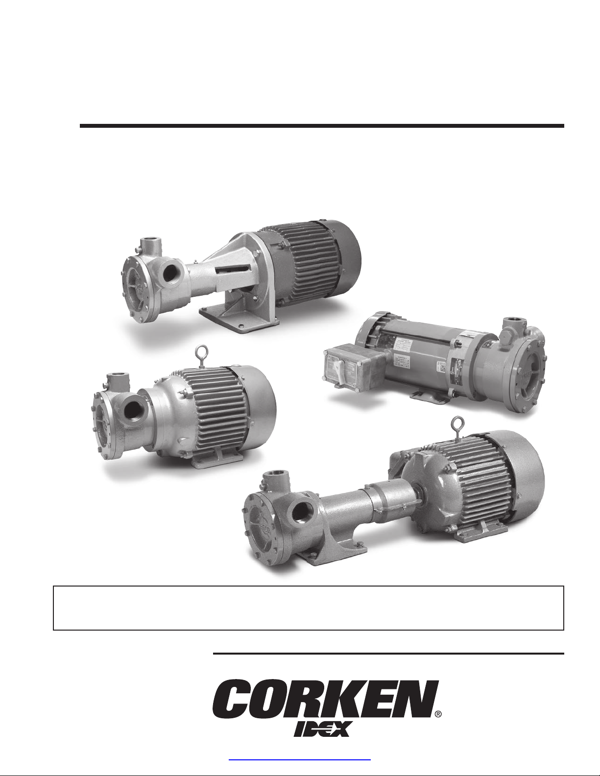
Chapter 2—Operation of Your
Coro-Flo
®
Pump
The following steps should be performed for the initial
pumping operation:
1. Close shutoff valve on the end of the delivery hose.
2. Open the storage tank bottom shutoff valve.
3. Open the storage tank shutoff valve of the bypass
system.
4. Check the motor for the proper voltage. (See
instructions in section 1.9 Driver Installation.)
5. Start the pump and circulate liquid through the bypass
system.
6. Adjust the B166 bypass valve by turning the adjusting
screw out until the pump pressure gauge shows
nearly the same pressure it did before you started the
pump. Screw the adjusting screw in until the pressure
gauge indicates the pump is starting to lose discharge
pressure (you will know this by the rapid fluctuating of
the pointer); then back the adjusting screw out a turn or
two until the pressure gauge again indicates a steady
pressure. Lock the lock nut, and permit the pump to
circulate liquid for a half hour or more. If the motor
overload protection device stops the motor during this
period, this indicates the bypass system valve is set too
high and should be readjusted by turning the adjusting
screw out until the motor will run for this period.
2.1 Filling New Cylinders and Tanks
All new containers are full of air and since air will not
liquefy under reasonable filling pressures, it must be
purged. To assure relatively easy filling and the proper
gas supply to burners and carburetors, purging air from
new containers is essential.
Some cylinders are difficult to fill because they are
equipped with a fill tube that extends down into the liquid
portion of the container. If possible, these cylinders
should be refitted, so the incoming liquid enters the
vapor section of the cylinder. If refitting is impossible or
impractical, rock the cylinder as it is being filled so that
liquid will splash up into the vapor section – this will help
keep the cylinder filling pressure down to a reasonable
limit. Don't blame your pump for not filling a small
container! A properly fitted cylinder and filling manifold
or connection will permit filling with not more than 50 to
60 psi differential pressure.
2.2 Pumping From Underground Tanks
The pumping of boiling liquids, like LPG and other
liquefied gases, offers a unique set of challenges for
underground tank installations. The Coro-Flo pumps
give superior performance in these applications if the
system is well designed to function with the pump in
mind. Liquefied gases are stored at exactly their boiling
points. Any increase in temperature, as well as any
decrease in pressure, will cause the product to boil and
form vapor. To minimize the amount of vapor formation
at the pump’s suction, the design of the suction piping
system is an important aspect. For boiling liquids, the
net positive suction head available (NPSHA) of an
installation is reduced to the height of the liquid level
above the pump minus the frictional losses. For an
underground tank where the pump is located above
the liquid level, the net static suction head becomes
the net suction lift, which is negative not positive. This
means that for aboveground pumps pumping from
underground tanks, the installation NPSHA will always
be negative, and the pump will always handle vapor in
the liquid stream.
The Coro-Flo regenerative turbine pumps are designed
to handle some vapor without the damaging effects of
cavitation. They are designed with a floating impeller which
minimizes wear and noise in these types of applications.
Properly installed, Coro-Flo pumps will provide excellent
service in underground tank applications.
8
www.northridgepumps.com

2.3 Installation Design Criteria For
Underground Tank Applications
Minimize frictional losses:
• Pump should be as close as possible to the tank’s liquid
outlet connection
• Use a minimal number of fittings and elbows
• No strainer is necessary since the tank itself acts as a
gravity collector
• Use full-port ball valves, or low restriction valves
• Use at least the minimum piping sizes shown in
Appendix I
• Minimize the net static suction lift to approximately 14
feet (4.3 M)
• Use vapor eliminator valves (Corken B166 by-pass
valves have this feature)
• Use back-pressure check valves downstream of the pump
• Vent the vapor eliminator on the liquid meter back to the
tank, not to the by-pass line
• Limit the capacity of the pump to a maximum of 1.5%
of the tank’s capacity or a 1000 Gal (3,785 L) tank, limit
the capacity of the pump to 15 gpm (56.8 L/min)
See Appendix I for piping diagram.
Chapter 3—Preventative Maintenance
for Your Coro-Flo®Pump
The only maintenance necessary on this pump is to
lubricate the bearings about once every six months.
The bearings have been lubricated at the factory for the
initial operation.
Lubrication for models C10, C12, C13 and C14:
These models are equipped with lifetime lubricated bearings.
Lubrication for models DL, DLF, DS, DSF, F, and FF in
pump sizes 9, 10, 12, 13, 14, and 15:
There are two bearings on the pump frame of these models
that require lubrication. In addition, if the pump is driven by a
motor there may be two bearings on the motor to lubricate at
the same time you lubricate the pump bearings. If the driver
is an engine, follow the engine manufacturer's instructions.
Lubricating the ball bearing is simple. Use ball bearing
grease only to lubricate the pump shaft bearing – nothing
else will do.
Older models without a grease zerk: Remove the plug
over the bearings, add a small amount of grease. With
the plug removed, run the pump and driver for several
minutes. The bearings will pump out the excess grease.
Replace the plug.
Newer pump models with a grease zerk: Remove the
lubricap covering the grease zerk and attach a grease
gun to the grease zerk. Add a small amount of grease and
cover the grease zerk with the lubricap.
Chapter 4—Repair Service on Your
Coro-Flo
®
Pump
After a long service life, repairs are limited to replacing the
impeller or mechanical seal.
The only wearing part influencing the pumping action
is the impeller, so we suggest the pump be given an
“efficiency” test before any attempt is made to repair
it. The trouble may lie in the piping system rather than
in the pump. If the pump will still produce as much
differential pressure when circulating through the bypass
system as it did when new, you may be sure your
problem is elsewhere. If the pump does not produce
as much pressure as it did originally, remove the cover
and inspect the impeller. If visual inspection indicates
the impeller is in good condition, remove one thin shim
gasket and replace the cover. Many times this procedure
will adjust for slight impeller wear. If the impeller is badly
damaged, it must be replaced (see step 32 in the seal
replacement instructions).
This is a matter of removing the cover and removing the
old impeller from the shaft. If the old impeller is tight on
the shaft, threaded bolt holes are provided in the impeller
to use for pulling. The new impeller must be a good slip
fit on the shaft; it should “float” on the shaft, so it may be
necessary to sand the shaft lightly to get the proper fit.
9
www.northridgepumps.com

Chapter 5—Coro-Flo
®
Seal Replacement Instruction
1. Please note these important Safety Tips
Periodic inspection and maintenance of the pump
is essential.
Inspection, maintenance, and installation of the pump
must be performed by trained personnel.
All procedures must comply with the Corken Installation,
Operation & Maintenance manual, applicable local
codes and safety standards.
The transfer of toxic, flammable, or explosive
substances is always at the user’s risk.
Equipment should only be operated by qualified personnel
according to applicable codes and safety standards.
Listed below are some written instructions for replacing
the seal assembly on all C-, DL-, DLF-, DS-, DSF-, F-,
and FF-model regenerative turbine pumps. A video
presentation is available on Corken’s website (see
Resources/Training Videos) and YouTube channel.
2. The model number of the pump is located on a name
plate on top of the pump casing.
If there is not a nameplate on the unit, there is a
stamped number on the cover and on the back of the
casing that indicates the model number.
This pump is a model C12. 9 would be a model 9, 0 is
a model 10, 2 a 12, 3 a 13, 4 a 14, and 5 is a model 15.
3. Note the direction of the rotation arrow on the front of the
pump cover. This is important to know when installing
a three phase motor such as the one used on model
C14 and all DL-, DLF-, DS-, DSF-, F-, and FF-models.
The motor can be wired to turn in a clockwise or
counterclockwise direction, so make sure it is wired to
match the direction of the rotation arrow when installing
a new motor. This wiring instruction does not apply to
the small C model motors of 2 horsepower or less since
they are wired to run one direction only.
4. All standard Coro-Flo regenerative turbine pumps use
the seal replacement kit 113-CXA. The letter at the
end of the part number indicates the O-ring material.
A is the standard configuration and indicates Buna-N.
Optional O-ring material is available and indicated
with a B for Neoprene, D for Viton, E for PTFE, G for
Ethylene-propylene, and K for Kalrez.
5. The boxed seal replacement kit includes:
• Important Instructions
• The stationary metal seat
• The rotating carbon with the seal sleeve assembly
and spring
10
www.northridgepumps.com

• The case cover O-ring
• The rear housing O-ring
• The follower and follower O-ring that seals to the shaft
• The impeller woodruff key
• The seal locking pin
• The seal clamp ring and 3 screws
• And, a .002 red and .003 green cover shim for adjusting
impeller clearance
6. The tools required for this procedure are:
• #2 phillips screwdriver
• #2 flat screwdriver
• 1/2” box wrench or 1/2” socket and ratchet
• Flat metal file
• 12” adjustable wrench
• O-ring pick
• Diagonal or side cutting pliers
• 300 to 400 grit emery cloth and scotch-brite
• You will also need a can of spray lubricant or light oil
and plenty of clean shop towels
7. Before you begin servicing the pump, make sure the
pump and system have been depressurized!
The seal replacement is an easy procedure so it’s not
necessary to remove the pump from the piping.
Keep the work area, tools and parts clean.
8. Begin by removing the bolts from the pump cover with
a ½” wrench or socket.
If you can’t remove the pump cover by hand, use the
cover bolts in the bolt holes located at the three and
nine o’clock position as pull or jacking bolts to help
remove the cover.
9. With the cover removed, note the number and color of
shims used for impeller clearance.
They will be discussed later in re-assembly.
This is the O-ring that seals the cover to the casing.
11
www.northridgepumps.com

10.Next, remove the impeller by pulling it off the shaft. If
it is stuck, insert an existing bolt from the pump cover
into one of the threaded pulling holes located on the
impeller. Remove the impeller by pulling on the bolt.
11. It’s okay if there is some light scoring or scratches on
the face of the impeller. As long as it can be shimmed
for proper clearance, the impeller may be re-used.
However, if any fins are damaged or broken, it will
need to be replaced. The matching model number is
stamped on the back of the impeller as well.
This is an example of an impeller that has discolored as
a result of heat caused by dry-running. This is the usual
cause of seal failure and excessive impeller wear. This
impeller is not damaged. As long as it can be shimmed
for proper clearance, the impeller may be re-used.
12. Next remove the woodruff key. With a pair of diagonal
cutting pliers, grab the key firmly and slowly roll up. DO
NOT drive the key out from the top with a screwdriver. You
may bend the shaft which will cause repetitive seal failure.
13. Before you remove the seal clamp ring, prevent the
pump shaft from rotating by inserting a screwdriver
between the fan blades and through the fan guard at
the rear of the motor. Remove the sleeve screws and
clamp ring using the Phillips screwdriver. A magnetic
screwdriver can make this a bit easier.
14. Remove the screwdriver from the fan guard at the
rear of the motor. To remove the locking pin, rotate
12
www.northridgepumps.com

the shaft so the locking pin is in the 6 o’clock position.
Compress the seal assembly with your thumbs and the
pin should drop out. A light press with a screwdriver
may help if the seal assembly does not move back.
15. Reach in with your fingers and remove the sleeve, follower,
and follower O-ring. If there are any nicks or burrs on the
shaft, removal may be difficult. Push the assembly back
in and use emery cloth to smooth and polish the shaft.
Repeat until the sleeve assembly slides out easily.
16. After you remove the assembly note the follower and
follower O-ring. The O-ring is compressed by the follower
when you tighten the seal clamp ring with the 3 screws. It is
critical that the shaft is smooth and clean for a positive seal.
17. To access the seal housing, remove the nameplate
located at the top of the pump casing and insert a flat
blade screwdriver in the opening.
Pry the seal housing forward with the screwdriver and
remove the housing from the pump.
18.After the seal housing has been removed, locate
and remove the shims behind the flange of the seal
housing. Make sure no shims have stuck to the inside
of the casing. Note the number of shims and set aside.
These shims will be re-used during reassembly and
are critical for proper seal compression.
19. Remove the metal stationary seat inside the seal
housing by placing the seal housing face down on a
flat work surface. Lightly tap the seat with a flat blade
screwdriver until it drops out. Or, using a small flat
blade screwdriver, gently pry the seat, rotating the
housing, until the seal drops out.
13
www.northridgepumps.com

20.Clean the inside and outside of the seal housing with
a spray lubricant or light oil and set aside. Polish with
emery paper if needed.
21. Next remove the rear casing O-ring with an O-ring pick.
22.Clean the groove in the casing by rinsing with a
spray lubricant.
23.At this time, rotate the shaft with your fingers. If there
is any roughness in the bearings or it slides in and out,
the motor or frame bearing may need to be replaced.
24.Before you reassemble the pump, now is a good time
to clean the front of the casing and the back of the
cover mating surfaces. Gently file or use emery cloth
to remove paint, rust and dirt from the surfaces. Then,
make sure you have cleaned all parts and surfaces
with a spray lubricant or light oil.
25.The first step of reassembly is to install the new O-ring in
the back of the pump casing. Begin by feeding the O-ring
into the groove and work it around with your fingers or a
flat head screwdriver until it is fully seated. Spray with a
light lubricant and wipe clean. Lubricating the O-ring will
help with the installation of the seal housing.
26.Next, install the new seal seat inside the seal housing.
14
www.northridgepumps.com

There is a locating pin in the back of the seal housing that
must align with the notch in the back of the seal seat.
To aid the installation process and prevent damage to
the seal seat, we recommend using a plastic handle
screwdriver. With the notch facing up, lubricate the
seal seat with light oil or spray lubricant and place
on top of the plastic handle screwdriver. Place the
seal housing over the seal seat and visually align the
locating pin with the notch in the seal seat.
Tap the housing down with the palm of your hand to
secure the seat in the housing.
If the pin is misaligned during the process, you may
use a small screw driver to align the notch of the seal
seat with the pin. Again, tap the seal housing down
with the palm of your hand to make sure the seal seat
is secure.
27. Reinstall all the metal shims, that were removed during
disassembly, behind the flange of the seal housing.
Slide the seal housing over the shaft and press into
the pump casing. Make sure the seal housing slides
through the O-ring and is seated to the back of the
pump casing. To confirm the seal housing is seated
completely, you may lightly tap the outer flange surface
on the front of the seal housing with a screwdriver. Do
not tap on the seal seat located inside the housing.
28.The seal assembly will need to be assembled before
it can be installed in the seal housing. Remove the
carbon from the retainer and apply lubricant to the
inner O-ring. Place carbon back on the retainer. Align
notches on the retainer with locators on the spring seal
assembly and press into place.
15
www.northridgepumps.com

Next, insert the follower O-ring and the follower into
the seal sleeve.
Make sure the follower notch aligns with the notch
on the seal assembly. Before installing, clean and
lubricate the shaft and surfaces again.
29.Rotate the pump shaft until the locking pin location is
at 12 o’clock. Insert a screwdriver into the fan guard to
lock the shaft in place. Slide the seal assembly over
the shaft and align the seal locking pin notch with the
pin location on the shaft. Compress the seal assembly
spring with both thumbs to expose the locking pin hole
on the shaft. Install the locking pin into the hole on the
pump shaft. Make sure it is seated in the locking pin
notch on the seal assembly. There should be some
clearance behind the pin when you compress the seal
assembly. And, enough spring pressure to hold the pin
in the notch on the seal assembly.
30.Next, install the seal clamp ring with three screws
using the Phillips screwdriver. A magnetic screwdriver
is helpful if available. Install all three screws before
tightening. Then tighten the screws evenly. Do not over
tighten or break the screws.
31. Remove the screwdriver from the fan guard and rotate
the shaft until the shaft key-way is at the 12 o’clock
position. Reinsert the screwdriver into the fan guard to
secure the shaft. Align the woodruff or impeller key into
the center of the shaft key-way. Using an adjustable
wrench, apply pressure to the key by gently rocking
the wrench up and down on the shaft while tightening
the wrench. Continue until the key is firmly seated and
flat in the key-way. Be careful to not damage or score
the shaft.
16
www.northridgepumps.com

Now, install the impeller. If the key has been properly
installed, the impeller should slide smoothly on the
shaft and go all the way to the back of the casing.
32.Impeller side clearance or float is set with the .002 red
and .003 green cover shims.
Caution: Use the minimum amount of shims to achieve
impeller clearance for maximum pump performance.
As the impeller wears, it may be necessary to remove
one of the shims to obtain the proper clearance. If
your pump has been in the field for a while, start the
shimming process by installing the cover O-ring with
the green shim only. Make sure the mating surfaces
of the pump casing and the cover are perfectly clean.
Adding a little lubricant will hold the shim in place.
Attach the pump cover making sure the Corken name
is level with the casing and cross-tighten with four
of the cover bolts. Rotate the shaft by inserting a
screwdriver in the fan guard and rotating the fan blade.
If the shaft does not spin freely with one green shim,
add the red shim for additional clearance.
Install and tighten the pump cover bolts evenly in a
crisscross pattern.
Rotate the pump several times to ensure there is no
rubbing or binding and to align and seat the seal assembly.
33.Now, close and secure the name plate on top of the
pump casing.
This completes the seal replacement procedure for all
C-, DL-, DLF-, DS-, DSF-, F-, and FF-model Coro-Flo
regenerative turbine pumps. If the pump is going back
into service, slowly pressurize with vapor. This can be
accomplished by slowly opening the bypass return line
on most systems.
If the pump is placed into short or long term storage, close
all openings and partially fill the pump with some light oil
to protect against rust and corrosion.
For intermittent duty, the frame bearings generally require
lubrication every three months.
However, continuous duty operations may require monthly
lubrication.
Corken recommends only using a MIL-G-10924C ball
bearing grease, with a temperature rating of -50°F.
17
www.northridgepumps.com

Appendix A—Model Number Identification Code and Available Options
C-Model (Close-Coupled) Regenerative Turbine Coro-Flo
®
Pumps
Appendices
A. Model Number Identification Code and Available Options
C-MODEL REGENERATIVE TURBINE PUMPS (CLOSE-COUPLED)
All Coro-Flo® close-coupled pumps are listed by Underwriters' Laboratories for LP Gas.
BASE MODEL # C10 C12 C13 C14 CF10 CF12 CF13 CF14
MODEL NUMBER
Inlet 1¼" NPT 1½" NPT 1½" NPT 1½" NPT
1½" ANSI
300 lb.
1½" ANSI
300 lb.
1½" ANSI
300 lb.
1½" ANSI
300 lb. BASE XXXX
Outlet 1" NPT 1" NPT 1" NPT 1" NPT 1" ANSI
300 lb.
1" ANSI
300 lb.
1" ANSI
300 lb.
1" ANSI
300 lb.
Weight bare pump
(lbs.)* 76 86 126 150 82 92 132 156
* Weight corresponds to standard motor.
SPECIFICATION FIELDS
2 hp, single phase,
115/208/230 volt,
50/60 Hz**
Standard Standard Standard NA Standard Standard Standard NA F
3 hp, three phase,
230/460 volt,
50/60 Hz**
Charge
Option
Charge
Option
Charge
Option Standard Charge
Option
Charge
Option
Charge
Option Standard G
** These motors are listed by Underwriters' Laboratories, Inc. and CSA for Class 1, Group D, explosion proof service. These motors do not have
internal overload protection.
Bronze impeller
Aluminum sleeve and
follower
Steel shaft
Seal Seat
Material Cast iron 2
O-ring Material Buna-N A
MOUNTING OPTIONS (with pump only)
Part Number
SM-30
S-30
ELECTRIC OPTIONS
Part Number
2277-X3
2277-X4
3784
NA = Not available
Standard
Standard D
Impeller, Seal
Sleeve, Follower
and Shaft
Material
Motor Selection:
Motor mounted starter for 2 hp motor.
Separate remote wall mounted starter for 2 hp motor.
Description
Motor mounted manual starter for 2 hp motor.
Wall mounted manual starter for 2 hp motor.
Switch only (used with the 2277-X3 and 2277-X4 manual starters)
Standard
Description
18
www.northridgepumps.com

Appendix A—Model Number Identification Code and Available Options
D-Model (Direct-Mount) Regenerative Turbine Coro-Flo
®
Pumps
D-MODEL REGENERATIVE TURBINE PUMPS (DIRECT MOUNTED)
DS models connect to motor frame size 56C through 145TC. DL models connect to motor frame size 182TC through 215TC.
All standard ANSI port sizes are 300 lb.
BASE MODEL NUMBER (NPT) DS9 DS10 DS12 DS13 DS14 DS15 MODEL NUMBER
Inlet 1¼" NPT 1¼" NPT 1½" NPT 1½" NPT 1½" NPT 1½" NPT BASE XXXX
Outlet 1" NPT 1" NPT 1" NPT 1" NPT 1" NPT 1" NPT
Ship weight, bare pump (lbs.) 52 52 52 52 52 52
BASE MODEL NUMBER (Flanged) DSF9 DSF10 DSF12 DSF13 DSF14 DSF15
Inlet 1½" ANSI 1½" ANSI 1½" ANSI 1½" ANSI 1½" ANSI 1½" ANSI
Outlet 1" ANSI 1" ANSI 1" ANSI 1" ANSI 1" ANSI 1" ANSI
Ship weight, bare pump (lbs.) 58 58 58 58 58 58
BASE MODEL NUMBER (NPT) DL9 DL10 DL12 DL13 DL14 DL15
Inlet 1¼" NPT 1¼" NPT 1½" NPT 1½" NPT 1½" NPT 1½" NPT
Outlet 1" NPT 1" NPT 1" NPT 1" NPT 1" NPT 1" NPT
Ship weight, bare pump (lbs.) 62 62 62 62 62 62
BASE MODEL NUMBER (Flanged) DLF9 DLF10 DLF12 DLF13 DLF14 DLF15
Inlet 1½" ANSI 1½" ANSI 1½" ANSI 1½" ANSI 1½" ANSI 1½" ANSI
Outlet 1" ANSI 1" ANSI 1" ANSI 1" ANSI 1" ANSI 1" ANSI
Ship weight, bare pump (lbs.) 68 68 68 68 68 68
SPECIFICATION FIELDS
Motor No integral motor C
Bronze impeller
Aluminum sleeve/follower
Steel shaft
Ductile iron impeller
Aluminum sleeve/follower
Steel shaft
Seal Seat Material Cast iron 2
Buna-N A
Neoprene® B
PART OPTIONS
Description
Coupling for DS model pumps (specify motor shaft size)
Coupling for DL model pumps (specify motor shaft size)
Neoprene® is a registered trademark of DuPont.
O-ring Material Standard
No charge option
Part Number
1344
1345
Standard
Standard
Impeller, Seal
Sleeve, Follower
and Shaft Material
Standard D
No charge option F
19
www.northridgepumps.com

Appendix A—Model Number Identification Code and Available Options
F-Model (Frame-Mount) Regenerative Turbine Coro-Flo
®
Pumps
F-MODEL REGENERATIVE TURBINE PUMPS (FRAME MOUNTED)
BASE MODEL NUMBER (NPT) F9 F10 F12 F13 F14 F15 MODEL NUMBER
Inlet 1¼" NPT 1¼" NPT 1½" NPT 1½" NPT 1½" NPT 1½" NPT
BASE XXXX
Outlet 1" NPT 1" NPT 1" NPT 1" NPT 1" NPT 1" NPT
Ship weight, bare pump (lbs.) 48 48 48 48 48 48
BASE MODEL NUMBER (Flanged) FF9 FF10 FF12 FF13 FF14 FF15
Inlet 1½" ANSI 1½" ANSI 1½" ANSI 1½" ANSI 1½" ANSI 1½" ANSI
Outlet 1" ANSI 1" ANSI 1" ANSI 1" ANSI 1" ANSI 1" ANSI
Ship weight, bare pump (lbs.) 52 52 52 52 52 52
All standard ANSI port sizes are 300 lb.
SPECIFICATION FIELDS
Motor No integral motor C
Bronze impeller
Aluminum sleeve/follower
Steel shaft
Ductile iron impeller
Aluminum sleeve/follower
Steel shaft
Seal Seat Material Cast iron 2
Buna-N A
Neoprene® B
MOUNTING OPTIONS
Description
Mounting Set-Up for Direct Drive.
Includes steel baseplate, flexible coupling, and coupling guard.
PUMP AND MOTOR NOT INCLUDED (b)(d)
Mounting Set-Up for V-Belt Drive.
Includes steel baseplate, adjustable driver slide base, V-belt drive and enclosed belt guard.
PUMP AND MOTOR NOT INCLUDED (b)(c)(d)
(a) Specify motor frame when ordering.
(b) Pricing based upon motor of current frame size, 3450 RPM, 60 cycle as shown on page A190, latest issue. Drivers of non-standard sizes may require additional
mounting charges.
(c) Pricing based upon motor of current frame size, 1750 RPM, 60 cycle as shown on page A190, latest issue. Drivers of non-standard sizes may require additional
mounting charges.
(d) There is an additional charge for mounting customer supplied motor. See page A180 for details.
Neoprene® is a registered trademark of DuPont.
256T
184T
103-12 (a) 215T
184T
215T
256T
Standard
D
F
101-8 (a)
Maximum Motor
Frame Size
145T
Impeller, Seal
Sleeve, Follower
and Shaft Material
O-ring Material
Standard
Standard
No charge option
Standard
No charge option
Part Number
20
www.northridgepumps.com
This manual suits for next models
13
Table of contents
Other Corken Water Pump manuals
Popular Water Pump manuals by other brands

Grundfos
Grundfos SCALA1 Installation and operating instructions

PVA
PVA PCP Series Operation manual

Sandpiper
Sandpiper S20 Service & operation manual

Bomba Elias
Bomba Elias R Series manual

Grundfos
Grundfos CRE Series Installation and operating instructions

CME Medical
CME Medical BODY GUARD 545 Operation manual