outlet or near it. A pressure gauge is necessary to
determine the efficiency of your pumping system.
2. A hydrostatic relief valve is required by most state
laws and for your own safety.
3. If the outlet piping exceeds 50 ft (15.2 m) in length a
check valve should be installed near the pump outlet.
The Bypass System Must Include the Following:
1. A pump bypass system must be installed. If the pump
discharge is shut off before the driver is stopped,
dangerously high pressures can develop, unless a
bypass valve is installed to permit the pump to discharge
back to the supply tank, at a predetermined pressure.
2. The pump may have an internal relief valve, but it is
intended as a safety relief valve device and not an
operational bypass.
3. Always install an external bypass relief valve (such as
the Corken ZV200 or B177) in the pump discharge line.
The bypass valve may discharge into the tank at any
convenient opening, either liquid or vapor; however, it
should not connect into the pump inlet piping system.
A Vapor Equalizing System Should be Included:
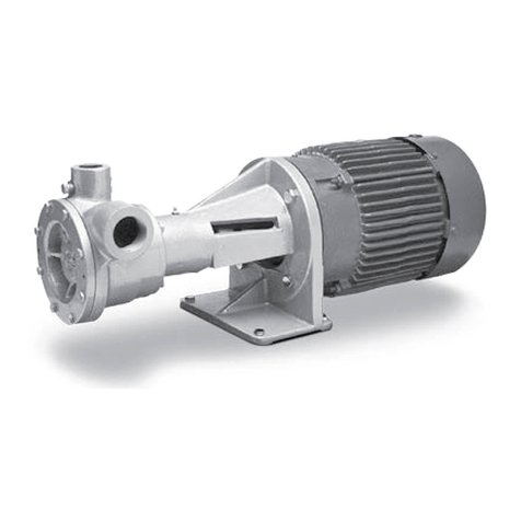
To obtain maximum performance from your Coro-Vane®
pump, a vapor equalizing system should be installed. This
system is simply a pipe connecting the vapor sections of
the tank being unloaded and the tank being filled. This
equalizing line allows vapor to move freely between the
two tanks (in either direction) and assures that both tanks
remain at the same pressure.
As liquid is withdrawn from a tank, it must be replaced
by an equal amount of vapor or the pressure in the tank
will drop. If an equalizing line is not present, this vapor
is formed by “boiling” of the liquid and a reduction of
the tank’s pressure. Meanwhile, the tank being filled
experiences a pressure increase as the rising fluid levels
compresses the vapor space above it. A vapor equalizing
line will eliminate both of these problems and will reduce
pumping time, differential pressure, noise and wear on
the entire system. Slow transfer rates will minimize these
effects, and reduce the need for a vapor equalizing line.
However, today’s high transfer rates require that a vapor
equalizing line be installed.
Another way to consider this principle is to remember
that it takes two holes in an oil can for oil to be poured
smoothly from the can; one for the oil to exit and the
other for the air to enter.
Driver Installation
The wiring of your electric motor is extremely important
and must be done by a competent electrical contractor.
The following wire sizing chart indicates the minimum
standards for wire sizes.
Improper motor wiring will cause expensive motor
difficulties from low voltage. If you suspect you have
low voltage, call your power company. Connecting your
motor for the voltage you have available is important
too. The motors furnished with the stationary pumps are
usually dual voltage, so you must be sure of the voltage
your power company is supplying you. Your motor will be
completely ruined if it is connected to the wrong voltage.
A humid climate can cause problems, particularly in
explosion proof motor applications. The normal breathing
of the motor, and alternating between being warm when
running and cool when stopped, often will cause moist
air to be drawn into the motor housing. This moist air will
condense, and may eventually add enough free water
to the inside of the motor to cause it to fail. To prevent
this, make a practice of running the motor and pump at
least once a week on a bright, dry day for an hour or so
(pumping through the bypass system). In this period the
motor will heat up and vaporize the condensed moisture,
and drive it out of the motor. No motor manufacturer will
guarantee an explosion-proof or totally enclosed motor
against damage from moisture.
Engine drivers pose a special consideration. The
manufacturer’s instructions must be followed. When the
stationary pump is equipped with an engine from the
factory, the engine speed should normally not exceed 1,800
RPM. Excessive engine speed will overload the engine and
cause early failure. The engine loses 3% of its power for
every 1,000 ft (305 m) above sea level, so if your installation
is at a higher altitude than normal, consult the factory.
Motor Recommended
wire size, AWG1
Hp Motor
phase Volts
Approximate
full load
amperes
Length of run (ft)
0–100 to 200 to 300
3111534.0 6 4 2
220 17.0 12 8 8
3230 9.6 12 12 12
460 4.8 12 12 12
5 1 115 56.0 4 1 1/0
230 28.0 10 6 4
3 230 15.2 12 12 10
460 7.6 12 12 12
7-1/2 1 230 40.0 8 6 4
3 230 22.0 10 10 8
450 11.0 12 12 12
10 3 230 28.0 8 8 8
460 14.0 12 12 12
15 3 230 42.0 6 6 6
460 21.0 10 10 10
20 3 230 54.0 4 4 4
460 27.0 8 8 8
25 3 230 68.0 2 2 2
460 34.0 6 6 6
30 3 230 80.0 1 1 1
460 40.0 6 6 6
40 3 230 100.0 2/0 2/0 2/0
460 52.0 4 4 4
50 3 230 130.0 3/0 3/0 3/0
460 65.0 2 2 2
1
Based upon 3% voltage loss copper wire type TW. Single phase
motor calculations are based on two times distance.
9


