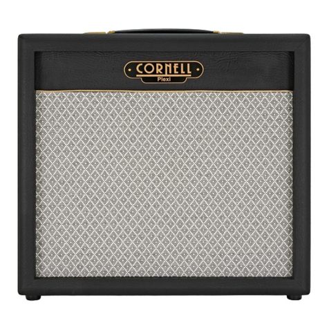
Cornell LegACy 30 Setup guide

CORNELL AMPLIFICATION.
OWNERS
INSTRUCTION MANUAL.
LegACy 30.
DC. Developments.
Musical Equipment Design & Development.
Unit 13 Rosshill Industrial Park, Southend-on-Sea.
Essex England SS2 5PZ Telephone 01702 610964

Page two.
INDEX
1. Introduction
Construction & design.
2. Technical Design
3. Controls.
4. Specification.
5. Tube Replacement
& Valve Failure.
Please Read All instructions before operating unit.
If you require any further information regarding the LegACy 30 amplifier or
other Cornell Products, please do not hesitate to contact us.
Cornell Amplification and equipment design and development
60 Eastcote grove Southend-on-Sea.
Essex England SS2 4QB Telephone 01702 610964
WWW. dcdevelopments.com.

Page 3.
Introduction.
Thank you for choosing a Cornell LegACy 30 amplifier.
Your amplifier employs valve technology. It is hand built to top standards.
Only high quality components are used so that you can enjoy years of
professional use.
Please take time to read this manual, to ensure that you get the
best from your amplifier.
Most guitarist of today will be aware of some amplifier history. The name
AC/30 must be one of the best known. This amplifier started life as a higher
powered version of the AC/15. Back in the 60’s when venues were getting
bigger and bigger, amplification needed to get louder for groups to be heard
so the AC/15 became the AC/30.
Construction & design.
The LegACy 30 is built in a similar way to that of the original AC/30 however
we have taken the basic design to its finest point, tailoring the components
and adjusting the circuit to produce the ultimate sound.
The LegACy 30 is not just a reproduction antique to be admired, it is made to
reproduce that classis sound of the AC4- AC15 and the AC30.
.
Legacy Sound.
The Legacy amplifier has a great tone that is instantly recognised and
emulated. Amplifiers of today try to offer a wide range of tones and sounds
resulting in a mass of controls that can confuse even the most enthusiastic
fiddler.
The result of this is that most amplifiers of today sound the same with a
noticeable loss of natural tone that can only be reproduced by simple design
and point to point wiring.
The LegACy 30 also contains unique Cornell design feature known
as the cream box.

Page 4
TECHNICAL DESIGN
Virtually all modern amplifiers are built using printed circuit boards, which
mean conductor tracks that connect components together, often run very
close to one another. When this happens a small capacitance is produced,
the result of which is a substantial loss in both high frequency response and
harmonic richness.
The Cornell LegACy 30 is designed to avoid this by having specific point to
point wiring.
Components in the LegAC 30 are mounted onto a specially designed panel,
connected using heat resistant wire and finally sealed using a conformal
coating to prevent noise and reduction of component life caused by moisture
penetration.
The Stainless steel chassis hold specially designed interleaved transformers.
The design ensures a very close reproduction of the full harmonic spectrum of
your guitar’s pick-ups.
The cabinet is made of high quality ply-wood. The covering is both heavy duty
and burn resistant. The grille on top of the cabinet is to assist air flow from the
valves by convection. The cabinet is handsomely finished and features a
heavy duty leather handle.
WARNING:
TO PREVENT DAMAGE, FIRE OR SHOCK HAZARD, DO NOT
EXPOSE THIS UNIT TO RAIN OR MOISTURE.
NO USER SERVICEABLE PARTS INSIDE, REFER SERVICING
TO QUALIFIED PERSONNEL ONLY.
THIS UNIT MUST BE EARTH GROUNDED.

Page 5
The Controls
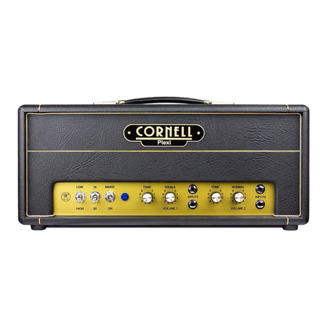
Input Hi & Lo.
The LegACy 30 has 6 inputs 2 for each of the 3 channels.
High impedance input connections for instruments.
Input Hi provides 6 db more gain than the Lo input.
Volume
There are 3 volume controls one for each channels each volume adjusts the
gain of the pre amp and is used to set the overall volume of the amplifier.
Tone.
channel one.
This is a pre-set bass cut switch.
Channel two
Tone.
Adjusts the amount of high and low frequency gain.
Bass
Channel Three.
Adjusts the amount of gain at the lower frequency range.
Treble.
Adjusts the amount of high frequency gain.
Cut.
Reduces the gain at the high frequency range on all 3 channels.
Output Switch.
AC4. Operates one output valve In single-ended class “A”.
AC15. Operates two output valves. In class “A in Push Pull”.
AC30. Operates Four output valve. In class “A in Push Pull ”.
Valve /diode Switch.
This changes the supply voltage to the valves to Valve rectification from Diode
rectification.
Stage/Studio
This reduces the power to ¼ of that set by the output switch
Standby.
Switches off the voltage to the valves but the heaters remain on.
Mains Switch Operation.
Do not operate the mains switch without a 30 second delay between
operations. An internal Thermistor reduces mains surges by introducing a
resistance. when switched on the Thermistor is heated and the resistance is
reduced. When switched off it requires a few seconds to cool to retain its
resistance before switching on again.

Output switch
Changes the speaker output from 8 to 4 ohms and is next to the output jacks.
Page 6
The Specification.
Power. 115 Volt AC 60 Hz. 120 watts US model.
230 Volt AC 60 Hz. 120 watts UK model.
Fuse. T 3 Amp. for 115 volt US model.
T 1.5 Amp. for 230 volt UK model.
Input Impedance. Hi Input 2,2 Meg Lo input 47 K ohms.
Controls Channel 1 Volume / Tone.
Channel 2 Volume Tone.
Channel 3. Volume treble, bass.
Master Cut.
Output. AC4. 5 watts.
AC15. 15 Watts.
AC30. 35 Watts
Dimensions. 60cm X 27cm X 24cm
23 ¾ X 10 ½ X 9 ½
Weight. 12 Kg 26.4 Lbs
Optional On Request. Material, Colours.
Warning.
To prevent damage. Fire or shock hazard, do not expose this unit
to rain or moisture.
No user serviceable parts inside, refer servicing to qualified
personnel only.

This unit must be earth grounded use correct mains cord.
Page 7
Tube replacement.
Tube (valve) life varies depending upon playing styles and application. Power
tubes have a much shorter life than pre-amp tubes which can last for years.
To maintain optimum performance of your amplifier, the tubes should only be
replaced with the same tubes specified on the tube illustration below.
When changing tubes, Always unplug the amplifier and remember
that the Tubes are Hot! Wait for the tubes to cool or replace tubes
when the amplifier has not used for several hours.
Your LegACy amplifier has 1. EF 86, 3. 12AX7, 1. 12AT7, 4 EL84, and 1
GZ34 tubes/valves.
Valve Failure.
When a tube /valve breaks down its internal elements can short. This can
cause major damage to the internal components of the amplifier and also be a
possible fire risk.
The mains fuse is designed to break under fault conditions, remember to
replace the fuse with the same type and rating.
Chassis Valve line up
Mains TX Output TX
GZ34 Output X 4 EL 84
12 AT7
EF 86
12AX7 X 3
Table of contents
Other Cornell Amplifier manuals

Cornell
Cornell Vintage Brown 10 User manual

Cornell
Cornell Custom 80 User manual

Cornell
Cornell Plexi 18 User manual

Cornell
Cornell Rambler 15 User manual

Cornell
Cornell Plexi 7 User manual

Cornell
Cornell Plexi Seven User manual

Cornell
Cornell Plexi 18/20 User manual

Cornell
Cornell Plexi 45 User manual

Cornell
Cornell Romany User manual