VIP Vision NVR Quick Start Guide - Version: VIPNVR-Q119
10
2.1.7 Conguring Basic Storage Settings
Here, you can congure the settings for situations when
the HDD is full, le size/time length of recorded video, and
the settings for auto-deleting old les.
•HDD Full: Congure the settings for when all the read/
write discs are full, and there is no more free disc.
•Pack Mode: Congure the time length and le length
for each recorded video.
•Auto-Delete Old Files: Congure whether to delete
the old les or not. If yes, also determines how many
days of footage are deleted.
NOTE: To conserve mobile data usage while using remote view, 320Kb/s Bit Rate is recommended for Sub Streams.
Encode Menu
•In the Encode menu, select each camera channel
and set the desired encoding options based on table
above (Fig. 2.14).
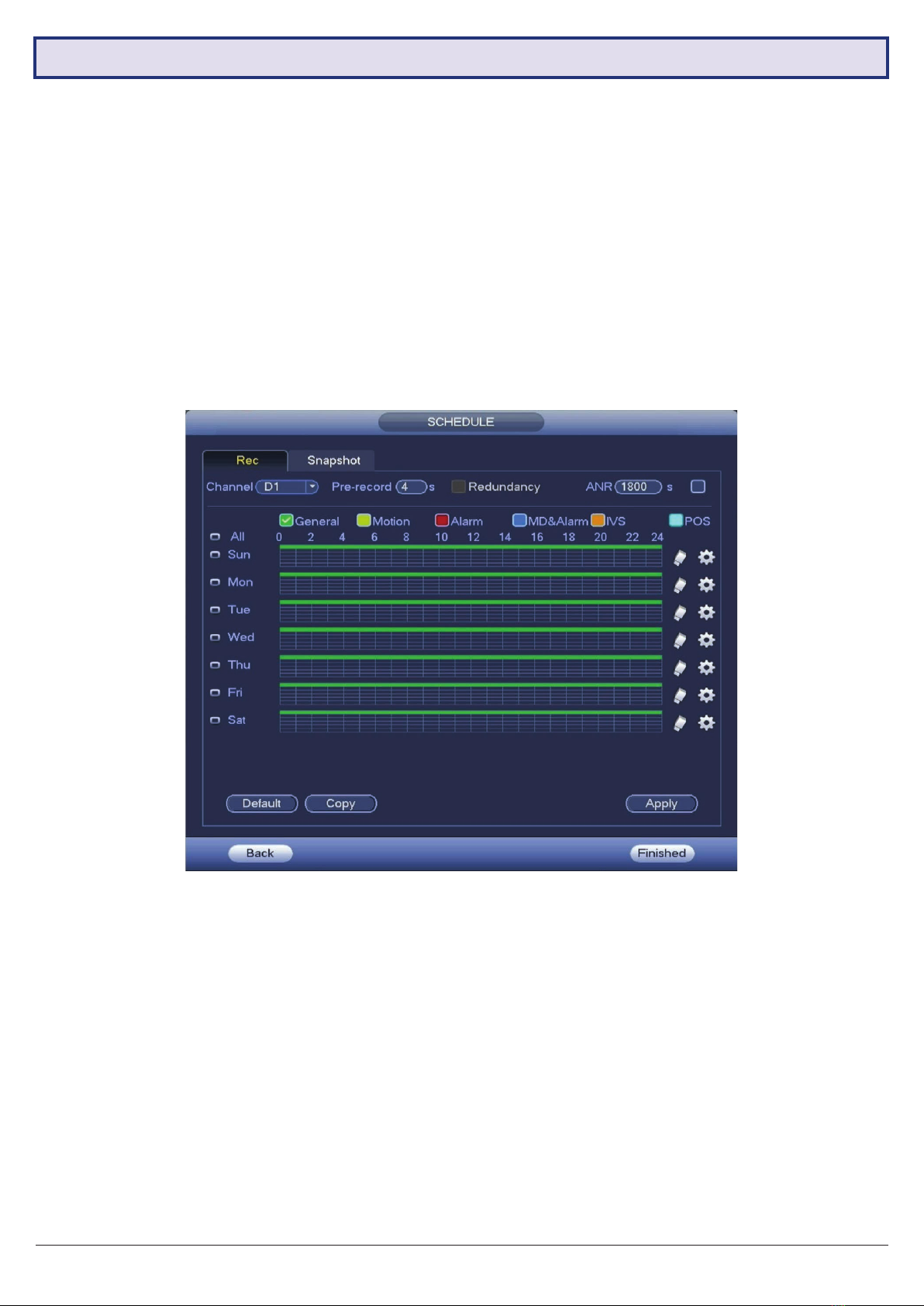
Snapshot Menu
•In the Snapshot menu, you can congure the NVR
to record image snapshots to be taken at Timing
intervals, based on the Snapshot Recording Schedule
(see Section 2.17), or on Trigger, via camera motion
detection.
•This creates image les alongside your recorded
footage.
Fig. 2.14: Suggested camera stream values to be set for individual cameras
Fig. 2.15: Encode setup section channel 1 settings example
(Quality Optimised)
Fig. 2.16: Storage Settings
Field Default Values Quality Optimised Recording Time Optimised
Main Stream Sub Stream Main Stream Sub Stream Main Stream Sub Stream
Resolution 1920 * 1080 352 * 288 1920 * 1080 704 * 576 1920 * 1080 352 * 288
Frame Rate 15fps 15fps 15fps 15fps 10fps 10fps
Bit Rate Type CBR CBR CBR CBR VBR VBR
Bit Rate 2048Kb/s 320Kb/s 4096KB/s 640KB/s 2048Kb/s 320Kb/s
Approx. Total
Record Time 8+ Days 4+ Days 14+ Days
2.2 Conguring Surveillance Cameras
2.2.1 Camera Quality & Bit Rate
After the Startup Wizard has been completed. You can congure the camera via the Encode menu. This section
determines the overall quality of footage recorded by your NVR. These can be adjusted to optimise for video quality or
recording time, depending on your preference.
Each camera features a Main Stream for high quality streaming to the NVR; and a Sub Stream for low quality, low data
streaming to your remote view phone or tablet. You can congure both of these streams for each individual camera,
so you can choose to prioritise quality for important cameras and recording time for others.
Fig. 2.21 details Default Values, Quality Optimised values and Max. Recording-time optimised values for a 2T HDD.
NOTE: Total record times below are estimates based on a 2.0MP system. Actual total record time will differ.