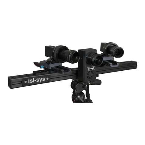
Correlated Solutions Vic-Gauge 3D User manual

Vic-Gauge 3D
T e s t i n g G u i d e
www.correlatedsolutions.com

1
Safety and Risk Management
Safety
Some mechanical assemblies contain pinch points - use proper care and tools
when assembling to avoid injury.
Incandescent lights can get very hot. Use caution when moving or working
around these lights, and beware of excessive heating of the specimen, cameras,
lenses, or other surfaces. Leave lights off when possible.
When mounting cameras it may be possible to create an unstable or unbalanced
situation. Be careful not to cantilever cameras excessively, especially heavier or
high-speed cameras.
Personnel should be in a safe location whenever a dangerous or destructive test is
being performed. Various solutions are available for extending cabling/controls to
allow the system to be operated in a safe, remote location –please contact
Correlated Solutions for more details.
Various paints, chemicals, and solvents may be used in preparing specimens for
testing. Always observe label precautions.
If any cables become frayed or damaged, replace immediately to avoid risk of
shock.
Do not attempt to repair or disassemble the computer or any electronic parts. Risk
of shock or damage may result.
Risk Management
Always fully support cameras when moving, assembling, or adjusting, until all
fasteners are completely tight. For larger high-speed cameras, two people may be
required. Cameras can suffer severe damage if dropped.
Always support lenses when installing or removing. In addition, for certain lenses,
during focusing operation, the front must be supported to prevent drops.
While most power and data connections are keyed, it may be possible to
incorrectly plug in or force a USB, 1394a, or 1394b connection. Always check
orientation and compatibility before making any connection.
For any test where excessive heat, shock, or flying debris may be present, take
steps to protect the cameras and equipment. Various shielding solutions are
available –please contact Correlated Solutions for more details.

2
Introduction
This guide explains the basic steps in running a Vic-Gauge 3D test, from start to finish. A
typical sequence will be:
Preparing the specimen
Setting up, pointing, and focusing the cameras on the specimen
Calibrating the camera system
Placing gauges
Setting the reference image
Analog connection and setup
Running the test
Preparing the specimen
Begin by preparing the region of interest on your specimen with a speckle pattern. For
more information on techniques and guidelines, please see the application note AN525,
Speckle Pattern Fundamentals. In this example, our specimen is prepared with a laser-
printed speckle pattern on adhesive paper.

3
Setting up the cameras
Pointing the cameras
To begin, set your prepared specimen in its testing location. Be aware of the orientation
and potential camera placement; for example, for a dog-bone specimen in a test frame,
the prepared face of the specimen should face outwards from the test frame rather than
facing the frame‟s columns.
Our test specimen for this example is a small demonstration fixture which is designed to
strain a small low-modulus material such as rubber (used here).
Make sure two cameras are connected, and start Vic-Gauge. You will initially be
prompted for a file name and location:
The prefix will determine the name of the output data files as well as any saved images.
All files and images will be placed in the selected path. You can click the …button to
select a new path, or type the path in directly. If you type a path that does not yet exist,
Vic-Gauge will prompt you and allow creating the path automatically.
Click OK, and the main window will appear; the two cameras will come up in a live
view.

4
The cameras are shown side by side; you can also view an individual image by selecting
the tab for a given camera. The red areas in each image indicate overdrive/saturation,
where the pixel is driven to its highest possible brightness value.
The images can be zoomed by placing the mouse over an image and using the scroll
wheel. This is useful for checking focus or examining details but affects only the display
and not the saved image or analysis.
To adjust the exposure time, use the large slider at the bottom of each window. The
typical default range is 0-50ms –to select a higher maximum, or a smaller range (to
allow finer adjustments), you can right-click on the slider. Select a preset, or “Custom” to
specify.
After starting Vic-Gauge, check the position of your camera rig. The distance between
the camera system and the specimen will be determined by your available lenses; when
multiple lenses are available, you should use the shortest one that works for your setup.
In some cases, test or room setup may require you to place the cameras farther away and
compensate with longer lenses; here, there are no such restrictions, so we use 8mm
lenses. The short lenses are generally easier to work with and can give somewhat better
results.

5
The distance is set so that the specimen fully fits in the field of view, while being close
enough to get a good image and use much of the camera‟s resolution. Note that the field
of view should be set with consideration to the final size and position of the specimen.
Here, because we expect axial tension, we‟ve allowed room for the specimen to strain.
Once a lens and approximate distance is selected, the cameras can be pointed. The
cameras should be positioned somewhat symmetrically about the specimen; this will keep
the magnification level consistent. The exact angle included between the cameras is not
critical but selecting a correct stereo angle will give best results: the angle should be at
least 25º for short lenses (8mm, 12mm), at least 20º for medium lenses (35mm), and at
least 15º for longer lenses (70mm). The angle should be kept below approximately 60º.
In the image below, we‟ve pointed both cameras correctly at the specimen. Note that the
image is well centered in both cameras, and that there is plenty of room for the specimen
to strain in tension:

6
Adjusting focus
When the cameras have been positioned, the next step will be to set focus. Use the focus
control on your lenses to achieve a sharp focus on the entire specimen. Often, it will be
helpful to zoom in on the image to check fine focus; with high resolution cameras, a
slight defocus will not be visible with the image zoomed out to fit on screen. While
zoomed in, look closely at both the far and near edge of the specimen to ensure that the
entire surface is in focus, before proceeding.
Tip: to aid in focusing, open the lens‟s aperture all the way. This will reduce the depth of
field and make any focus issues very obvious. Then return the aperture to the appropriate
setting for the test. (You will need to temporarily reduce the exposure time to compensate
–see following section.)
Focusing with large aperture –small DOF
After closing aperture –focal plane is well
centered
Depth-of-field
Depth-of-field
Specimen
Focal plane
Camera

7
Aperture and exposure time
As you make the image sharp through the focus adjustment, it will also be necessary to
adjust the brightness of the image. There are two controls available for this: the
aperture/iris setting on the lens, and the exposure time setting of the camera.
Aperture: opening the aperture allows more light to fall on the sensor. The
aperture setting is also called the f-number; f-numbers are usually indicated on the
lens‟s aperture ring and typically go from an open setting of F/1.4 or F/2.8 to a
closed setting of F/22 or F/32. Using a bigger aperture (lower f-number) will
make the image brighter. However, it will also decrease the depth of field –the
range over which the focus is sharp. Even for a flat specimen, some depth of field
is necessary because each camera is oblique to the plane of the specimen; also,
poor depth of field may make it difficult to achieve a wide range of calibration
target positions (see following section).
At higher magnifications and with higher resolution cameras, care should be taken
when using very small apertures (high F-numbers). In some cases this can limit
resolution due to diffraction; for example, with a 5 megapixel camera and a 75mm
lens, using apertures of F/11 or higher will result in very blurry images. In these
cases it will be necessary to find the best balance of depth of field (requiring high
F-numbers) and resolution (requiring low F-numbers).
Note that the aperture may not be changed after the system is calibrated.
Exposure time: this is the amount of time the camera sensor gathers light before
reading out a new image. Longer exposure times make the image brighter but can
also create blur if significant motion happens during the exposure times. For
many tests, blur is not a concern for the specimen itself, but can be an issue when
acquiring images of a hand-held calibration grid. A rule of thumb is to keep the
exposure time below 1/f, where f is the focal length of the lens (in mm). So, for a
50mm lens, this would mean a limit of approximately 20ms.
In contrast to aperture, exposure time may be adjusted after the system is
calibrated if lighting conditions change or the specimen becomes brighter/darker.
Controls for focus and aperture differ by lens; two common C-mount styles are shown
below.

8
This lens has a focus and
aperture ring, each with locking
knob. The aperture ring is
normally closest to the camera.
Loosen the locking knob (if
present); make any adjustments;
and tighten the lock before
calibrating.
This lens has an aperture ring
with a locking knob. To focus,
loosen the collar (for this
particular lens, a 2mm hex
driver is used), and rotate the
entire body of the lens. Loosen
the lens body
(counterclockwise) to focus
closer; tighten (clockwise) to
focus farther. Tighten the collar
when complete.
Caution –the lens body is not
captive and will fall if screwed
all the way out.
When exposure and aperture settings are complete, the image should be bright and there
should be no overdriven (red) pixels in the area of interest. In many cases, ambient
light will not be enough to achieve this without using unacceptably large exposure times
or aperture settings; for these cases, supplemental light will be required.
Too bright –overdriven
Too dim
Correct brightness

9
For many moderately sized specimens, a simple task lamp of 50-100 watts will give
excellent light levels while providing diffuse, even illumination. For very small
specimens at high magnification, a fiber optic illuminator can be used. For very large
specimens, a 300-500 watt halogen light or a specialized machine vision lighting solution
may be required. If the specimen is reflective or highly curved, specialized solutions or
careful positioning may be required to avoid reflections/highlights on the surface.
WARNING: If the light is positioned in front of and below the cameras, or if the
surface begins to heat up from the lighting, refractive heat waves can appear in your
image. These waves may not be visible in a zoomed out image but when zooming in
they can be seen as a swimming/shimmering effect which can both defocus and
distort the image.
If heat waves are present in your image they can easily introduce false strains of
several thousand microstrain so it is critical that they be avoided.
Heat waves can be minimized by either repositioning the light source, or, if
necessary, a small desk or stand fan can be set up to blow across the scene. This will
generally mix the air well enough to completely eliminate the heat waves.
To conclusively check for heat waves, you can simply run the Vic-Gauge analysis
with no load/motion. If heat waves are present, you will see large displacement and
strain fields that change randomly over time.
Once the camera positions have been set and the focus and aperture adjusted, calibration
can begin. After this point, changing any aspect of the camera system will invalidate the
calibration; so, all adjustments should be carefully fixed at this point.
Tighten the tilt and rotation adjustments on the camera mounts.
Lock the focus and aperture adjustments on the lenses, if possible.
Tighten the tripod column.
Tie the camera cables firmly to the tripod or crossbar; this will prevent external
force on the cables from applying leverage to the cameras.

10
Calibration
Once the focus, aperture, and camera position are set, the system must be calibrated.
Selecting a grid
To begin, select a grid that approximately fills the field of view.
Slightly too small
Correct
Too large
If the grid is too small, it may be difficult for Vic-Gauge to automatically extract points;
additionally, more total images will be required to cover the field of view, including the
corners. However, if no ideally sized grid is available, smaller grids will usually work
well.
If the grid is too large, it will be difficult to keep it fully in the field of view in both
cameras while taking images. However, calibration images will be useful as long as all
three of the hollow marker dots are visible. If any of the three marker dots cannot be
seen, then the image cannot be used.
Occasionally, lighting configuration can affect grid selection. Some grids may be slightly
reflective; under intense or directional light sources, these reflections can wash out the
grid image. For these cases, especially matte grids should be used, or care taken to avoid
reflections.
Positioning the grid
The calibration procedure calculates variables about the camera geometry and imaging; it
is not specific to a plane or volume in space. Therefore, it‟s not necessary to position the
calibration grid in the exact same location as the intended specimen. Still, it will be most
convenient to place the grid in roughly the intended plane. This will ensure that the
cameras point at it correctly and that the grid is in good focus.
Sometimes, the depth of field will be so short that you cannot calibrate in front of the
specimen. In this case you may have to remove the specimen and place the grid in its
location, then replace the specimen.
If the specimen cannot be moved and there is insufficient depth of field to calibrate in
front of the specimen, it may be necessary to move or rotate the stereo rig for calibration.
In this case, it is very important not to disturb the camera position. The best way to
achieve this may be to smoothly rotate the entire mount; this involves a minimum of

11
vibration and shock compared to dragging the tripod away. Then, calibrate to the left or
right of the specimen position before returning the rig to center.
If the tripod must be moved, it may be helpful to mark the original location of each leg;
otherwise, finding the original rotation and position may be difficult.
Acquiring grid images
At least four calibration images must be acquired. More calibration images will give a
more accurate result; in addition, acquiring redundant images leaves more room to
discard poor images (images that contain highlights, defocus, obstructions, or other issues
that makes them unsuitable for use). For a typical setup, 15-20 images will be a good
number.
To acquire calibration images, capture several images of the grid in various poses.
Include significant rotations about all 3 axes.
To accurately estimate perspective information, the grid should be tilted off-axis
and/or moved closer/farther from the cameras for some images.
To estimate aspect ratio accurately, the grid should be also rotated in-plane in
some images
To estimate distortion accurately, grid points should cover the corners of the
image field in some images. If a small grid is used, this will require specifically
moving the grid to each corner and acquiring images. If the grid nearly fills the
field, it will naturally fill in the corners.
For each image pair, the grid should be visible in both images. If calibration is
performed in roughly the same plane as the specimen, this will happen naturally.
Calibration images should be fairly well focused across the width and height of
the target.
If a grid dot is partially off the edge of the image, it will be discarded. However, if
it is partially blocked by, i.e., a thumb, Vic-Gauge may estimate the center
incorrectly. This should be visible as a high error for that particular image.
Some overdrive/saturation is acceptable, as long as black grid dots don‟t begin to
appear shiny and white.
To capture each grid image, click the Calibration Image button on the toolbar:

12
Computing Calibration
To calibrate using the acquired grid images, select the Calibration tab at the toolbar to the
right.
Use the Grid pulldown to select the grid you used –in our case, a 9mm grid. Then, click
Analyze. The points will be automatically extracted from each image, and a calibration
computed.

13
Each image is displayed with an error score, and a final error score is displayed at the
bottom. Lower scores are better; any scores displayed in red are marginal or too high.
Selecting distortion order
Distortion order can be chosen using the spin box at the bottom of the dialog.
For lenses with higher distortion orders, more images may be required, and it becomes
even more important to take grid images where points are present in the corners of the
field of view. As many as 30 images may be required to accurately estimate 3rd order
distortions.
High-magnification calibration
For macro lenses and small fields of view, it will become very difficult to get significant
off-axis tilt in the target without severe defocus. Because of this, the “center” values may
be poorly estimated. The best remedy is to attempt to get as much tilt as possible to get a
better estimate, but failing this, the High magnification option will force the center
values to be the numerical center of the lens.
Calibration results
If your calibration score is high, there may be a problem with the setup or images. Check
that:
The grid images are in focus.
The exposure times are short enough to eliminate motion blur.
The cameras are secure on the stereo rig.
The grid is rigid.
The grid is evenly lit. For a backlit glass grid, this is particularly important.
If using a glass grid, confirm the correct face is towards the camera.
The results are displayed in a tree below the scores. Each calibrated value has both a
result and a +/- confidence interval (smaller confidence intervals are better). Confidence
intervals that are higher than usual might indicate a problem –generally, too few
calibration images, or not enough motion/tilt in the images.

14
Center (x,y): the position on the sensor where the lens is centered. It should be
roughly in the physical center of the sensor.
The confidence intervals for center (x) and (y) will generally be higher for long-
focal-length lenses. At very small fields of view and high magnification lenses
(70mm and up), the interval may be higher in magnitude than the value itself –if
the centers themselves are reasonable then it‟s okay to proceed. If a reasonable
center estimate cannot be obtained, you may need to check the High
magnification option (see above).
Focal length (x,y): the focal length of the lens, in pixels. Multiplying this number
by the known pixel size of the camera will give a number roughly equal to the
specified focal length of the lens.
Skew: indicates the out-of-square of the sensor grid.
Kappa (1, 2, 3): the radial distortion coefficients of the lens.
Rig: the geometry, described as the relationship of camera 2 to camera 1.
When a good calibration is achieved, click Accept to finish. The calibration tab will show
a green checkmark.

15
Placing gauges
Once the cameras are set up, you can place one or more virtual gauges on the specimen.
To place a gauge, right-click in the camera 0 (left) image, and click Add gauge here.
A virtual gauge will appear on the surface.
The gauge has three yellow nodes that can be dragged. Drag the node at the top left of the
text box to reposition the label:

16
To change the size of the gauge, click and drag the node at the lower right:
Larger gauges will compute more slowly and average over a larger area. Using a larger
gauge can also give much more accurate strain results especially when strains are small.
To move the gauge itself, click and drag the center node.
You can place multiple gauges. Note that placing too many gauges will cause correlation
to slow down somewhat and frames may be missed.

17
To create a virtual extensometer, click and drag on the center of one gauge. Drag the
gauge on top of another gauge; a line will appear. Release the mouse button to complete
the extensometer.
A virtual gauge measures a position (X, Y, Z), a displacement (U, V, W), and a
strain tensor (strain in X, strain in Y, shear strain). These values are computed
over the entire gauge area and reported at the gauge center.
A virtual extensometer measures only length, and a simple extension strain
(ΔL/L). This is measured between the two selected gauges. Because the virtual
„gauge length‟ can be longer than with a single virtual gauge, the strain result may
be more accurate.
To delete a gauge or extensometer, right-click on the yellow node at its center, and select
Delete gauge.

18
The reference image
Once all gauges have been placed, you can select a reference image. This image defines
the reference state of the object; all deformations and strains will be relative to this
image. To select this image, click the Reference icon in the toolbar.
Vic-Gauge will attempt to place the gauges in the camera 1 (right) image in the matching
positions.
In some cases, the initial point may not be found automatically. In this case, you can drag
the gauge in the right image to the approximate start point and click Reference again.
Once a reference is established, some basic position and size information will be
displayed in the table at the bottom of the screen.
For each gauge, a reference position is displayed (for an extensometer, this is the center
position). We also see a subset size, a physical size, a sigma value (matching confidence;
always -1 for an extensometer since there is no match associated); and a projection error
(also always -1 for an extensometer). If the projection error is high, it will be displayed in
red, and probably indicates a false match. In this case an initial guess may be needed (see
above).

19
Analog connections and setup
If a data acquisition device is connected, you can configure analog inputs and outputs. To
start, select the Controls tab at the right.
You may configure up to two voltage outputs to produce a voltage proportional to one of
your strain measures. For each ouput, to enable, click Enable. Then, select a gauge to
use, and the relevant strain component. Gauges will have a full strain tensor;
extensometers have only a principal strain (e1).
Select the scale to apply. For example, with the default of 1%strain/volt, the output will
go up to 10V at 10% strain (-10V at -10% strain). Be aware of levels of strain noise and
expected strain levels during the test.
These outputs may be used as part of a machine control loop but caution should be used.
Be sure to set all applicable limits to avoid damage to your machine or specimen.
Because this is a non-contacting technique, it is susceptible to more fluctuation than, i.e.,
a clip extensometer.
Table of contents
Other Correlated Solutions Measuring Instrument manuals