Corsa 14254 User manual

CHEVY SSR
2004 Removal Instructions:
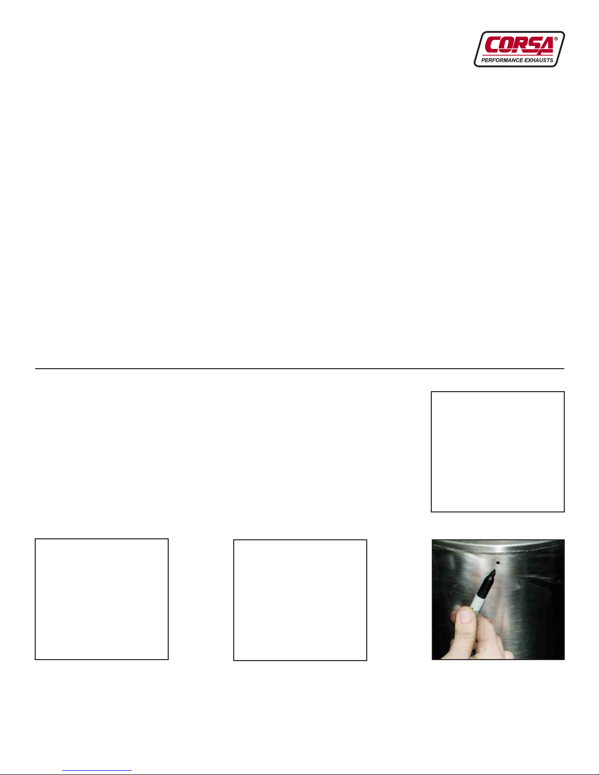
1) Scribe line approximately 2-3 inches down from frame brace (passenger
side). See Fig. A
2) Cut pipe as far upward as possible toward the “Y” section (passenger
side). See Fig. B
3) After cutting through pipe, remove passenger side segment as shown
in Fig. C.
4) Cut the driver side stock pipe as close as possible to spot indicated by
arrow in Fig. D.
5) Cut the driver side pipe as indicated in Fig. E.
TOOLS NEEDED: Safety glasses, 15 mm wrench or deep socket, 1/2” wrench or deep socket,
Torque wrench, saw or cutting wheel, chain-style pipe cutter, soapy water solution, ruler and
black marking pen
FIG. B
FIG. A
FIG. C
FIG. D
FIG. E
2004-06Chevrolet SSR
PN 14254 / PN 14255
Exhaust System Installation
All Torca clamps should be tightened using a
properly calibrated Torque Wrench. Using an air
impact gun will damage the clamp and reduce its
ability to effectively seal the joint. It may also cause
the joint to separate thereby causing damage to
your exhaust system and your vehicle.
INSTALLATION NOTE:
Be sure to apply the provided anti-seize lubricant
to all bolts, fasteners and clamps. A pouch is
included with the hardware kit. Apply the supplied
anti-seize lubricant to the threads ONLY of all
TORCA band clamps. Failure to follow this
procedure can cause the nuts to seize on clamps
and potentially damage threads. WARNING: Be
sure to thoroughly clean hands after use. Anti-
seize lubricant will tarnish stainless steel parts.
CAUTION: Prior to installation, be sure your vehicle
is parked on a level surface, and the exhaust
system is cool. For safety purposes and ease of
installation, we urge you to take your vehicle to a
qualified service center or muffler installer that
employs the use of a lift.
TORCA CLAMP
Position slot
90°off of bolt
Position
clamp at
end of
expanded
tube

6) After completely cutting pipe in previous step, remove the driver side
segment from hanger grommet. Spray some soapy water in grommet
to help. See Fig. F
7) Scribe a line 3 inches in front of stock muffler inlet. See Fig. G
8) Cut pipe approximately 3 inches in front of muffler inlet, as shown in Fig. H.
9) Loosen nuts at flange connection. Use a 15mm socket to remove flange nuts. See Fig. I
10) Remove Head Pipe section from grommet as shown. Spray some soapy water in grommet
to help. See Fig. J
11) Remove cross bar bolts and cross bar from frame rails. See Fig. K
Be careful. The muffler is resting on the cross bar at this point.
12) Remove final section (muffler and “Y” pipe) from grommet as shown in Fig. L. Spray some
soapy water in grommet to help. Carefully remove pipe from the rest of the vehicle.
FIG. G FIG. H
FIG. F
FIG. I FIG. J FIG. K
FIG. L

FIG. M
FIG. N FIG. O FIG. P
2005 Removal Instructions:
1) Cut Driver Side Tail Pipe using chain style cutting device. Remove the Driver
Side Tail Pipe section from the vehicle. See Fig.’s 1 & 2.
2) Cut the 1/2” rod connecting the two tailpipes near the differential using a cut-off wheel or sawsall.
See Fig. 3.
3) Cut the Passenger Side Tail Pipe approximately 3” past the muffler exit. Remove the Passenger Side
Tail Pipe section from the vehicle. See Fig. 4.
4) Follow step 7 -12 on page 2 of instruction pamphlet to complete the removal of the stock
exhaust system.
FIG. 1 FIG. 2 FIG. 4
FIG. 3
CORSA System Install Instructions:
1) Install CORSA Head Pipe shown in Fig. M.
2) Pre-tighten nuts using a 15mm socket as shown in Fig. N. Do not
completely tighten nuts on Head Pipe until the rest of the CORSA
system is in place.
3) Install muffler, ensuring drain hole is facing toward the ground.
See Figures O & P.

4) After the muffler is assembled to the Head Pipe, swing the cross bar
into place and tighten bolt as shown in Fig. Q. Tighten bolt to a
torque of 60 ft.-lbs.
5) Next, assemble the Y-Pipe section of the CORSA exhaust system to
the muffler exit. (See Fig. R)
6) Tighten the Y-Pipe section to the muffler exit using the 3” Torca
clamp provided with your system. See Fig. S. When installing the
Y-pipe hanger section to the factory grommet, make certain to rotate
the grommet 180°so that the Y-Pipe hanger is above the factory
hanger. Make sure the muffler is supported and level when installing
the Y-Pipe. Do not tighten the clamp completely until the rest of the
system is in place.
7) Slide the rubber grommet simultaneously onto the Y-Pipe hanger
and the chassis hanger. Spray some soapy water in grommet
to help. (See Fig. T)
8) After the grommet has been installed onto the Y-Pipe section of
the assembly, your pipes should look similar to those in Fig. U.
9) Install the passenger side pipe assembly to the Y-Pipe section of
the system. (See Fig. V)
10) Pre-tighten the passenger side section to the Y-Pipe section using
a 2.5” Torca clamp (See Fig. W). Clamp is provided with your system.
Do not tighten the clamp completely until the rest of the system
is in place.
11) Install the driver side section of pipe
(See Fig. X) to the Y-Pipe assembly.
12) Slide expanded end of driver side section
onto driver side Y-Pipe. (See Fig. Y)
FIG. Q
FIG. S
FIG. T FIG. V
FIG. W FIG. X FIG. Y
FIG. R
FIG. U

13) Place the grommet shown in Fig. Z onto the hanger of the driver side
pipe assembly. Then tighten down the 2.5” Torca clamp at the Driver
Side Tail Pipe to Y-Pipe connection. Do not tighten the clamp
completely until the rest of the system is in place. Spray some soapy
water in grommet to help.
14) At this point, your pipes should look similar to the SSR rear view
shown in Fig. AA.
15) Begin to install the CORSA 4” Pro-Series tips on both the driver and
passenger side tail pipes. Continue to Step 16 on next page.
16. Place the 4” Pro-Series tips onto both tailpipes. The tips should be
recessed approximately 3/8” inside the tip pocket. The tabs on the
clamps must be facing toward the center of the vehicle. At this time
the clamps can be fully tightened. (See FIG. BB)
17. Install the tie bar with the side that has the hole thru the tab between
the tabs on the passenger side clamp. Use the bolt and nut provided
in the hardware kit to hold the tie-bar in place. (See FIG. CC)
18. Slide the Tie-Bar between the tabs on the driver side clamp.
NOTE: The tab attached to the Tie-Bar on the Driver Side is slotted.
This is to give the installer adjustment when finalizing the tip alignment.
(See FIG. DD)
19. Align the Driver side tip so that it is concentric with the opening in
the bumper then tighten the nut and bolt through the clamp tabs and
tie bar. (See FIG. EE)
20. See FIG. FF for a view of the Tie-Bar fully assembled to the driver
and passenger side clamps.
21. The tips should be evenly spaced with the completion of the Tie-Bar
assembly as shown in FIG. GG.
Now you may completely tighten ALL Torca clamps on the exhaust
system to the Torca torque specification of 45 ft.-lbs.
Finally, finish tightening the nuts at the flange connection shown on
page 3 in Fig. N. When tightening flange bolts, alternately tighten
each bolt so the spacing is even all the way around the flange
connection. Uneven tightening may result in an exhaust leak.
Torque the flange nuts to 60 ft.-lbs.
FIG. Z
FIG. AA
FIG. BB
FIG. CC
FIG. DD FIG. EE FIG. FF FIG. GG

Head Pipe
16SR4000
Sport Muffler
14686
Passenger Side
Pipe Assembly
16SR4008
Driver Side
Pipe Assembly
16SR4009
Hardware Kit
16SR7003
FIG. 5
FIG. 6
FIG. 7
2004-05 Chevrolet SSR Exhaust System
Adjustment Section
1) The alignment of the tips can be adjusted at two
locations: The rear hanger sections of the
Passenger and Driver Side Tail Pipe.
2) Begin with Passenger Side Tail Pipe Hanger
Assembly. If necessary, loosen the two 1/2” nuts
shown in Fig. 5. Once the nuts have been
loosened, the hanger assembly can slide
sideways a 1/2” in either direction or 1” of total travel.Adjust to desired position
and tighten the two nuts to lock the Passenger Side Tip into position.
Torque the nuts to 15 ft.-lbs.
3) Adjusting the Driver Side Hanger Assembly requires movement in the
vertical direction. If necessary, loosen the two 1/2” nuts shown in Fig. 6.
Then move the tip up and or down until you reach the desired position.
Torque the nuts to 15 ft.-lbs.
4) Once this process is complete, the tips should be perfectly centered
as shown in Fig. 7.
Y-Pipe
16SR4015
Pro-Series
4” Tips
16MC3000
Touring Muffler
14687
This manual suits for next models
1
Table of contents
Other Corsa Ventilation Hood manuals
Popular Ventilation Hood manuals by other brands

Broan
Broan EWP1306SS instructions

Ancona
Ancona UC64NL User's manual & installation instructions

Ancona
Ancona WPRL430 User's manual & installation instructions

Philco
Philco APIA 60 L user manual

Miele
Miele PUR 68 W Operating and installation instructions

Hotpoint Ariston
Hotpoint Ariston HLQV 6 AB Instructions for use