manuals.online logo
Brands
  1. Home
  2. •
  3. Brands
  4. •
  5. Corsa
  6. •
  7. Ventilation Hood
  8. •
  9. Corsa 14866 User manual

Corsa 14866 User manual

Cat Back Exhaust System
Single Side Exit w/ Twin 4.5” Pro-Series Tips
2014+ Chevrolet Silverado/GMC Sierra 1500 6.2L
143.5” & 153” Wheel Base
PN: 14866, 14866BLK
Please take time to read and understand these installation instructions.
CORSA recommends that the installation of this system be performed by a qualified service center or professional
muffler installer who has the necessary equipment, tools and experienced personnel. However, if you decide to
perform this install, the use of a lift and an additional person will be required.
CAUTION: Never work on a hot exhaust system. Allow time for the vehicle to cool. Always wear eye protection when
working under a vehicle.
Recommended Tools:
3/8” drive ratchet
3/8” drive 13mm deep socket
3/8” drive 15mm deep socket
Small flathead screwdriver or similar tool
Chain-style pipe cutter or similar device
Grommet pullers
Soap and water solution
Torque Wrench
Penetrating lubricant spray
Safety glasses
Please confirm that all parts are present before beginning the factory exhaust system removal and CORSA exhaust
system installation.
Bill of Materials
1. 16SE2034 –Muffler Assembly
2. 16SE3028 –Tip Assembly
3. 16SE4474 –Head Pipe Assembly
4. 16SE4478 –Tail Pipe Assembly
5. 16SE4487 –153” WB Adapter Pipe
6. 16SE7100 –Hardware Kit
Cat Back Exhaust System
Single Side Exit w/ Twin 4.5” Pro-Series Tips
2014+ Chevrolet Silverado/GMC Sierra 1500 6.2L
143.5” & 153” Wheel Base
PN: 14866, 14866BLK
Factory Exhaust System Removal:
1. Beginning near the flex section, loosen the clamp using the ratchet and 13mm deep socket. (Fig A)
Note: Penetrating lubricant may make this step easier.
2. Downstream of the flex section, remove the hanger from the rubber grommet using grommet pullers or a
similar device. (Fig B)
Note: A soap and water solution may aid in the removal of hangers.
3. Support the front portion of the exhaust system (just in front of the muffler) using a jack stand or similar device.
4. Remove the two hangers from the rubber grommets downstream of the muffler using grommet pullers or a
similar device. (Fig C)
Note: At this point, the exhaust is only supported by the jack stand and the hanger near the tip. Take care to not
let the exhaust system tip or roll as it may damage the vehicle and/or cause personal injury.
5. Using the grommet pullers, remove the last hanger near the tip. (Fig D)
6. Carefully remove the factory exhaust system from the vehicle by first twisting the system within the chassis and
pushing it backwards to clear the chassis bracing at the front and then pulling the exhaust system forward.
Note: Take care to not damage the brake lines or wires near the rear axle when moving the exhaust system. If
you are not able to move the system rearward enough to clear the chassis bracing near the front of the factory
exhaust, cutting the factory exhaust system will be required. We suggest cutting the exhaust in front of the
tunnel muffler using chain-style pipe cutters or a similar device.
7. Using a small, flathead screwdriver or similar device, gently pry the retaining tab just enough to remove
spherical clamp from the factory exhaust system. (Fig E) Keep the clamp for later use during installation of the
Corsa exhaust.
8. This concludes the factory exhaust system removal process.
Cat Back Exhaust System
Single Side Exit w/ Twin 4.5” Pro-Series Tips
2014+ Chevrolet Silverado/GMC Sierra 1500 6.2L
143.5” & 153” Wheel Base
PN: 14866, 14866BLK
Factory Exhaust Removal Pictures
Fig. A Fig. B
Fig. C Fig. D
Fig. E
Cat Back Exhaust System
Single Side Exit w/ Twin 4.5” Pro-Series Tips
2014+ Chevrolet Silverado/GMC Sierra 1500 6.2L
143.5” & 153” Wheel Base
PN: 14866, 14866BLK
Installation of CORSA Exhaust System:
NOTE: Apply the anti-seize lubricant (supplied) to the threads ONLY of all the clamps and flange bolts. Failure to follow this
procedure can cause nuts to seize on clamps and potentially destroy threads. After applying anti-seize lubricant, be sure to
thoroughly clean your hands, as lubricant will tarnish stainless steel. All clamps should be tightened using a properly calibrated
Torque Wrench. Using an air impact gun will damage the clamp and reduce its ability to
effectively seal the joint. It may also cause the joint to separate, thereby causing damage
to your exhaust system and to your vehicle.
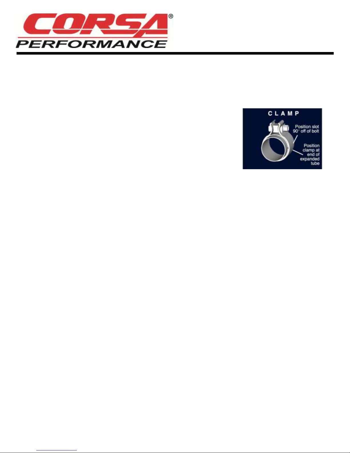
NOTE: Align all clamps so that the center of the clamp bolt is 90 degrees from the notch in
the pipe. (See Fig. CLAMP)
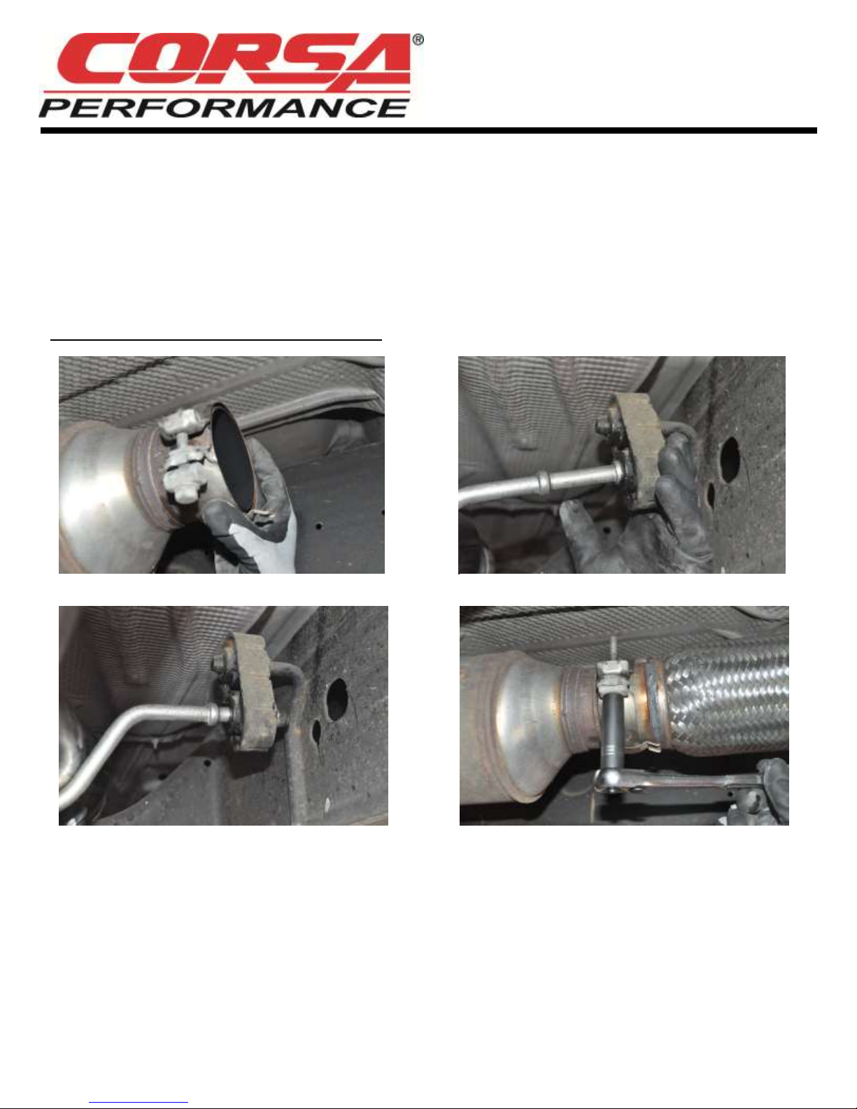
1. Begin by reinstalling the spherical clamp onto the end of the factory Y pipe. Install it
such that the bolt is on the driver’s side of the pipe while the hex head is toward the
ground to more easily facilitate tightening. (Fig A)
2. Locate the headpipe and insert the hanger into the rubber grommet. (Fig B) Insert the spherical form of the headpipe into the
spherical clamp and adjust the headpipe such that the part of the hanger inside the rubber grommet is level and parallel to the
ground. (Fig C). Use a temporary spacer between the headpipe and frame rail, and snugly tighten the spherical clamp using the
ratchet and 13mm socket. (Fig D).
For 143.5” wheel base trucks, skip to Step #4. For 153” wheel base trucks, continue to Step #3.
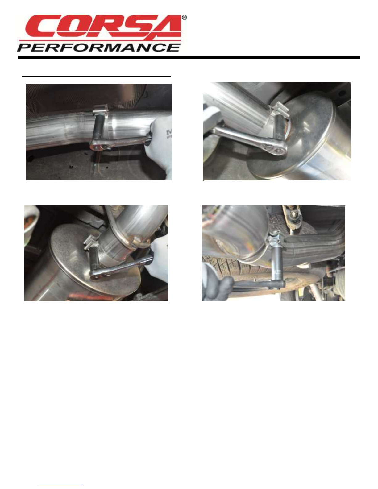
3. Locate the short, straight length of pipe with the expansion on one end. Slide a 3.5” clamp over the expansion and then slide it
over the outlet end of the headpipe. Orient the clamp such that the bolt is on the driver’s side of the pipe with the nut towards
the ground. Snugly tighten the clamp using the ratchet and 15mm socket. (Fig E).
4. Locate the muffler and another 3.5” clamp. Slide the clamp over the expanded inlet of the muffler and then slide the muffler
onto either the end of the headpipe (143.5” WB trucks) or the end of the 153” adapter pipe (153” WB trucks). Make sure the
drain hole in muffler is oriented downwards. Snugly tighten the clamp using the ratchet and 15mm socket. (Fig F)
5. Locate the tail pipe and another 3.5” clamp. Slide the clamp over the expansion and from the rear of the vehicle, feed the pipe
over the rear axle. Insert the hangers into the rubber grommets both near the muffler and the single hanger near the end of
the tail pipe. Adjust the tail pipe such that the portion of the hangers inside the grommets are level and parallel to the ground.
Snugly tighten the clamp using the ratchet and 15mm socket. (Fig G)
6. Locate another 3.5” clamp and the tip assembly. Slide the clamp over the expansion and then slide the tip assembly onto the
tail pipe. Adjust rotation of tip assembly to align the tips with the rear bumper and the side of the truck bed. Snugly tighten the
clamp using the ratchet and 15mm socket. (Fig H)
7. Ensure the exhaust system is adjusted properly making sure the headpipe is not contacting any bracing, the axle pipe is not
contacting the rear axle or chassis, and that the tip is adjusted to preference. Once satisfied, beginning at the front of the
vehicle, fully tighten down all clamps using a torque wrench. Tighten the spherical clamp using the 13mm socket to 31ft-lb and
the 3.5” clamps to 45ft-lb using the 15mm socket. Make sure to remove the temporary spacer from Step #2 at this time if it is
still in place.
Cat Back Exhaust System
Single Side Exit w/ Twin 4.5” Pro-Series Tips
2014+ Chevrolet Silverado/GMC Sierra 1500 6.2L
143.5” & 153” Wheel Base
PN: 14866, 14866BLK
NOTE: During cold weather start-ups, you may experience an exhaust sound that is deeper and louder in tone
than usual. This is temporary and will diminish to normal levels once your engine has reached its normal
operating temperature.
NOTE: Immediately following the installation of your exhaust system, you may experience a trace of smoke
after initial start-up. DO NOT be alarmed. The smoke is caused by the burning of a small amount of forming oil
residue used in the manufacturing process.
CORSA Exhaust Installation Pictures
Fig. A Fig. B
Fig. C Fig. D
Cat Back Exhaust System
Single Side Exit w/ Twin 4.5” Pro-Series Tips
2014+ Chevrolet Silverado/GMC Sierra 1500 6.2L
143.5” & 153” Wheel Base
PN: 14866, 14866BLK
CORSA Exhaust Installation Pictures:
Fig. E Fig. F
Fig. G Fig. H

This manual suits for next models

1

Other Corsa Ventilation Hood manuals

Corsa 14172 User manual

Corsa

Corsa 14172 User manual

Corsa 14254 User manual

Corsa

Corsa 14254 User manual

Corsa 14247 User manual

Corsa

Corsa 14247 User manual

Popular Ventilation Hood manuals by other brands

Turboair Ticino Instruction on mounting and use

Turboair

Turboair Ticino Instruction on mounting and use

ROROS HETTA SENSE User instructions

ROROS HETTA

ROROS HETTA SENSE User instructions

Air King Range Hood SEV30SSH Specifications

Air King

Air King Range Hood SEV30SSH Specifications

Range Master BELHD80 instruction manual

Range Master

Range Master BELHD80 instruction manual

Air King P1030 Brochure & specs

Air King

Air King P1030 Brochure & specs

FAL AWS-P55A 90CM instruction manual

FAL

FAL AWS-P55A 90CM instruction manual

Range Master 63000 Series instructions

Range Master

Range Master 63000 Series instructions

Euro Chef COKRHIEUCAC10 user manual

Euro Chef

Euro Chef COKRHIEUCAC10 user manual

Air King PIN30 operating manual

Air King

Air King PIN30 operating manual

ROROS HETTA CRYSTALL F-1140 user manual

ROROS HETTA

ROROS HETTA CRYSTALL F-1140 user manual

VentAHood EUROLINE installation instructions

VentAHood

VentAHood EUROLINE installation instructions

BLUE STONE HOB-8735 user manual

BLUE STONE

BLUE STONE HOB-8735 user manual

foc.us MEDIOLAN Assembly and maintenance instructions

foc.us

foc.us MEDIOLAN Assembly and maintenance instructions

Range Master RM51000 Series User instructions

Range Master

Range Master RM51000 Series User instructions

Master cook WK-Cristal Use and care guide

Master cook

Master cook WK-Cristal Use and care guide

AirPro 06E Series Installation instructions & use & care guide

AirPro

AirPro 06E Series Installation instructions & use & care guide

Turboair SOFIA H6 IX/A/60 Instruction on mounting and use

Turboair

Turboair SOFIA H6 IX/A/60 Instruction on mounting and use

KOBE CHX-30 Series(400 CFM-LED) Installation instructions and operation manual

KOBE

KOBE CHX-30 Series(400 CFM-LED) Installation instructions and operation manual

manuals.online logo
manuals.online logoBrands
  • About & Mission
  • Contact us
  • Privacy Policy
  • Terms and Conditions

Copyright 2025 Manuals.Online. All Rights Reserved.