Costalab Labyrinth User manual

Labyrinth
Advanced-Switchboard
User Manual

INDEX
- Introduction…………………………………………………………………………………………….............3
- Front amp effects connection…………………………………………........................................................4
- Four cables method connection …………………………………………...................................................5
- Operating modes…………………………………………............................................................................6
- Storing a preset…………………………………………...............................................................................7
- Front Panel…………………………………………........................................................................................8
- Rear Panel………………………………………….........................................................................................9
- Menu…………………………………………...............................................................................................10
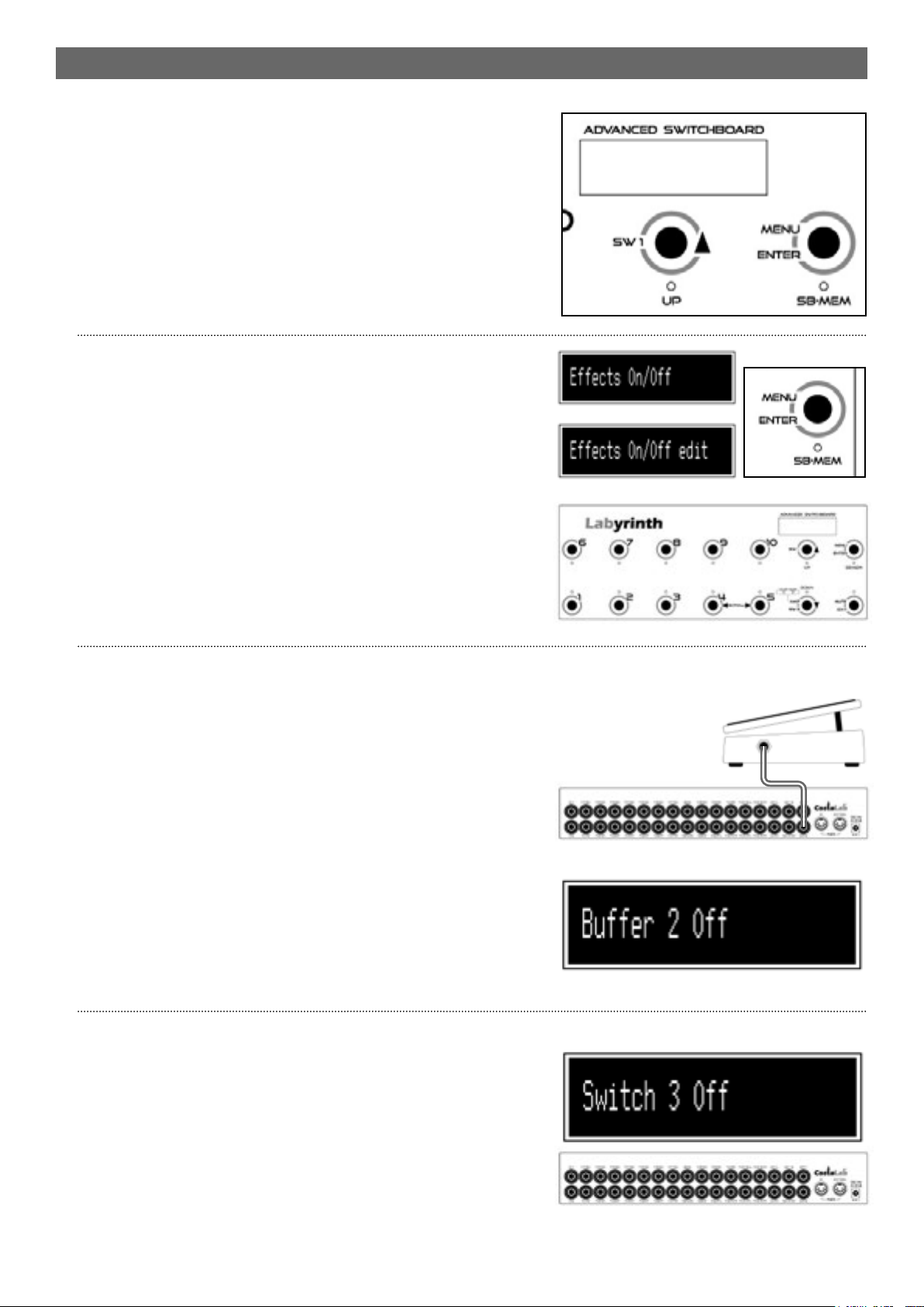
- Effect On Off…………………………………………..................................................................................10
- Buffer 2…………………………………………...........................................................................................10
- Switch 3…………………………………………..........................................................................................10
- Switch Mode…………………………………………..................................................................................11
- Amp Select………………………………………….....................................................................................11
- Pedal management………………………………………….................................................................11-12
- Program Change and Control Change………………………..................................................................12
- Tap Tempo…………………………………………......................................................................................12
- Name…………………………………………..............................................................................................13
- Midi ChTx/Rx………………………………………….................................................................................13
- Midi Thru…………………………………………........................................................................................13
- Wireless…………………………………………..........................................................................................13
- Device Name………………………………………….................................................................................13
- Write…………………………………………...............................................................................................13
- Factory Restore…………………………………………..............................................................................14
- Update Firmware…………………………………………...........................................................................14
- Firmware version…………………………………………...........................................................................14
- Expression pedal calibration…………………………………………........................................................14
- Block diagram……………………………………………………………………………………..................15
- Switch and expression pedals diagram…………………………………………………………...............15
- Technical specications………………………………………………………………………………….......16

ATTENTION
Please read this user manual carefully before powering up the pedalboard and strictly adhere to
the instructions.
Be sure to use only the supplied AC adapter which operates at 9-12 V DC.
Please do not open the 230-12V power supply and do not damage nor modify the power supply
cord.
CostaLab will not be responsible for any damage to the product caused by unauthorised
modications to electrical and electronical parts.
COSTALAB LABYRINTH
Labyrinth pedalboard is designed to switch pedal effects in true-bypass.
You can activate/deactivate up to 10 pedals (or pedal sequences) individually (SB Mode - Stompbox
Mode) or in programmed mode (MEM)
With LABYRINTH you can:
- Maintain the signal quality along the effect path.
- Easily change complex sounds without having to switch on and off individual pedals
- Switch amp channels
- Manage an external multieffect processor or pedals via MIDI
FEATURES
- 10 true bypass loops (send/return) for “front amp” effects or: 7 true bypass loops (send/return) for
“front amp” effects and 3 “stereo” true bypass loops for amp send/return effects.
- 3 control switches and analog TAP TEMPO out.
- Programmable Amp A/B output.
- 10 “stomp box” buttons with status LED. These buttons directly activate effect loops. (Stomp Box
Mode)
OR
- 10 preset buttons (1-10) to recall the effects combination and switch settings. MIDI (MEM Mode).
- UP/DOWN buttons for MIDI bank change (1-5, 6-10, 11-15, 16-20, 21-25, etc.). Also used for MIDI
channel change and switch function selection.
3

CONNECTIONS: 10 LOOPS FRONT AMP
Pedals have to be connected as indicated in the above schematic. Make sure every pedal is
activated and powered on. To include or exclude a pedal from the signal path, simply press the
corresponding pedalboard button.
FRONT AMP LOOPS 1-7 FRONT AMP LOOPS 8-10
4

4
CONNECTIONS: 7 LOOP FRONT AMP + 3 LOOP SEND/RETURN
Pedals have to be connected as indicated in the above schematic. Make sure every pedal is
activated and powered on. To include or exclude a pedal from the signal path, simply press the
corresponding pedalboard button.
FRONT AMP LOOPS SEND RETURN LOOPS
AMP
SEND AMP
RETURN
5

OPERATING MODES
Labyrinth could be used in two different modes:
“SB” (Stomp Box) Mode
In this mode, the 10 dedicated buttons include or exclude the relative pedals in the signal path.
When “SB” mode is selected, “SB” is displayed on the screen and the leds above the stomp buttons
indicates which effects are in the signal path.
“MEM” (Preset) Mode
MEM Mode (Memory Preset) allows you to recall any effect combination previously saved. You can
store up to 520 presets. Every preset can be modied in real time by switching in SB Mode and
using the loop buttons.
In “MEM” mode the display shows the current preset with a letter “A-Z” (Bank) and a number from
1 to 10 (Preset).
Using 1 to 10 buttons you can recall the relative preset of the current Bank. By pressing the “UP” or
“DOWN” buttons you can select the bank from Ato Z(1-260) or from A to Z (261-520).
N.B. When choosing a new bank, the current preset is not changed until you select a preset of the
new bank.
Switching between “SB” e “MEM” mode is done by briey pressing the “Menu/Enter/SB.MEM”
button.
If the “MEM” Mode is active, the green indicator “SB-MEM” under the “Menu/Enter/SB.MEM”
button is lit.
6

6
STORING A PRESET
1) Enter “SB” Mode by holding “Menu/
Enter/SB-MEM”
2) Press the buttons corresponding to the
pedals you want to insert in the signal
path. Led indicators will light up.
3) Press and hold the “Menu/Enter/SB-
MEM” button until main menu is displayed.
4) Again, press and hold the “Menu/Enter/
SB-MEM” button until “Write to” appears
on the display.
This sequence represents an “on the y” storing process, to save the patch that is selected in that
moment.
5) Use UP and DOWN buttons to select the bank where to save the new patch. Use 1 to 10 button to
choose in which memory location store your preset.
Simply press “ENTER” button to conrm. “COMPLETE” will appear on the display to conrm the
saving of the preset in the pedalboard memory.
Long Press
Long Press
7

FRONT PANEL (SB “STOMP BOX” Mode)
Switch 1...10: activate/deactivate the relative effect loop.
Switch SW1: activate the analog switch (dry contact) for amp channel switch or similiar functions.
Switch SW2: hold this button for more than 2 sec. to activate a second analog switch (dry contact)
for amp channel switch or similiar functions.
Switch AMP: press this button to sequencially cicle between amp A, B, or A+B out; use this to select
the desired destination AMP.
Switch MEM: commutes between SB and MEM Mode.
Switch TAP: sends tap tempo via MIDI message or analogically using a static switch on the tip of
SW3/TAP jack.
Switch MUTE: hold for more than 2 sec. to activate the MUTE Mode and enables the TUNER output
of TUNER jack.
FRONT PANEL (MEM “PRESET” Mode)
Switch 1...10: select patches in the current bank.
Switch UP e DOWN: allows to select a memory bank.
Switch MEM: cycles between SB and MEM Mode.
Switch MUTE: hold for more than 2 sec. to activate the MUTE Mode and enables the TUNER output
of TUNER jack.
Switch TAP: sends tap tempo via MIDI message or analogically using a static switch on the tip of
SW3/TAP jack.
8

8
REAR PANEL
IN A guitar input
IN B buffered guitar input (Pedal EXP1)
FX SN 1....7 effect send jacks (connect to pedal input)
FN RT 1...7 effect return jacks (connect to pedal output)
SEND out of the rst 7 loops chain, connect to amp input (If no jack is inserted, all
10 loops are connected in series)
RETURN loops 8, 9 and 10 input, connect to AMP SEND
FX8-SN loop 8 send (connect to effect input)
FX8-RT loop 8 return (connect to effect output)
FX9-SN loop 9 send (connect to effect “mono” input)
FN9-RT-L loop 9 left stereo return (connect to effect Left output)
TUNER tuner out
FN9-RT-R loop 9 right stereo return (connect to effect Right output)
FX10-SN-L loop 10 left stereo send (connect to effect Left input)
FX10-RT-L loop 10 left stereo return (connect to effect Left output)
FX10-SN-R loop 10 right stereo send (connect to effect Right input)
FN10-RT-R loop 10 right stereo return (connect to effect Right output)
SW 1-2 AMP channel switch jacks (via dry contact)
SW 3-TAP dry contact switch (Ring) and static-switch for TAP-TEMPO (Tip) control
EXP-1 Expression pedal input (Pedal 1) to control buffer 1 volume
EXP-2 Expression pedal input (Pedal 2) to control buffer 2 volume
MIDI IN MIDI IN socket
MIDI OUT-THRU MIDI OUT-THRU socket
DC-IN 9-12Vdc input socket
9

MENU
In SB Mode, hold the MEM button until led SB/MEM
blinks. Edit Menu has many conguration options. The
display always shows the last option selected. Select
which parameter to modify using the UP/DOWN buttons,
press ENTER, then use UP/DOWN buttons to set the
value and eventually press ENTER again to conrm.
A description of editable parameters is provided below.
Effect On/Off
Allows effect loops (from 1 to 10) to be included in the
signal path.
Press again the ENTER button, the screen shows “edit”
indicating that you are in the effect choose mode.
Pressing number switches 1-10 turns each effect loop
on/off.
Corresponding LEDs indicate the loops included in the
signal path.
Buffer 2
Buffer located after loop 7. It can be activated/
deactivated.
If activated allows to control the signal level of the effect
chain usually connected to the Send/Return of an amp
via an expression pedal connected to EXP2 jack.
The pedal value controls the amount of signal owing
into the effect chain connected to the amp Send/Return
maintaining reverb and delay tails.
Pedal position is stored in the patch. Therefore it is
possible to set a patch main volume for each individual
patch.
Switch 3
Analog switch on SW3-TAP jack. activable only in MEM
Mode.
When this parameter is ON the analog switch is activated
and allows to switch amplier channels.
When a patch is recalled and the parameter is ON, the
switch is closed.
Master Volume
Scegliere i loop da attivare
Premere Enter
10

Premere Enter
10
MENU
Switch Mode
Set the working mode of the 3 analog switches:
Options are: Latch, Timer 250ms, 500ms and 1000ms.
In Latch mode the switch is closed and held closed until
another patch is selected.
In the other modes, the switch is closed and held closed
for the amount of time selected.
These modes are useful for devices that use “Unlatched”
pedals.
Amp Select
Labyrint features two separate outputs for two amps or
as stereo outputs of stereo effects connected to loops 8,
9 or 10.
This parameter selects the active output: A, B, or A+B..
To use Labyrint in stereo select the A+B mode.
EXP PEDALS
Pedal 1/2 On/Off
Activates the EXP1 pedal on the IN-B input buffer or
EXP2 pedal on buffer 2.
Once the pedal is active, the signal is fully analogic
controlled using the expression pedal connected to the
relative jack.
Pedal position is stored into the patch and recalled when
the patch is selected.
Using EXP1 Pedal
This funcion is used to have different sounds depending
on the pedal position.
For example let’s store a patch with the loop 2 ON
containing an Overdrive with a high gain.
Set ON the EXP1 pedal and move the pedal position
at 1/4. The resulting sound will be a light crunch as we
lowered the guitar volume knob. Then store a patch with
these settings. Now move the pedal position at 3/4 so
the resulting sound will be a higher gain one. Store this
sound as a new patch.
Set now the pedal at maximum, the sound will be a lead
sound corresponding to the Overdrive setting. Let’s
store this third patch.
Select these 3 different patches to recall a Lite Crunch,
Crunch and Lead sound without even touch the pedal
knobs.
Input Volume
Pedal 1/4 lite crunch
Pedal 1/2 crunch
Pedal Full Lead
11

PEDAL MANAGEMENT
Pedal 1/2 Value
Indicates the current volume value of EXP1 or EXP2
Pedal (from 0 to 1023).
This parameter can be set also if no pedal is connected
to the EXP jack.
Pedal 1/2 Min:
Sets the minumum value of EXP1 or EXP2 Pedal (from 0
to 1023).
Pedal 1/2 Max:
Sets the maximum value of EXP1 or EXP2 Pedal (from 0
to 1023).
Pedal 1/2 MIDI cc:
Sets the Control Change sent via MIDI Out with EXP1 or
EXP2 Pedal.
Pedal 1/2 mode
Three working modes:
- Int (acts as volume pedal, EXP1 for Buffer 1, EXP2 for
Buffer 2)
- Ext (sends Control Change)
- Int. Ext. (sends Control Change and acts as volume
pedal simultaneously)
PROGRAM E CONTROL CHANGE
PC Tx MIDI Ch
Sets the Program Change (from 1 to 128) sent via MIDI
and MIDI Channel (from 1 to 16).
CC Tx N Val
Sets the number (from 0 to 127) and value (from 0 to
127) of relative Control Change.
CC Tx MIDI Ch
Sets the MIDI Channel (from 1 to 16) of relative Control
Change.
You can set up to 5 Program Change and 5 Control
Change simultaneously.
TAP TEMPO
TAP MIDI Ch
These parameters set the kind of tap tempo sent via
MIDI:
- Notes and value,
- Control Change and value,
- MIDI Channel
Use Scroll buttons to switch between parameters.
Rx Clock
If On, Labyrinth can receive MIDI clock from an external
device.
12

12
MENU
Name
Set patch name. Use UP and DOWN buttons to change
characters, use SCROLL button to move between letters.
MIDI ChTx/Rx
Set general MIDI channel for EXP1 and EXP2 pedals.
Thru On/Off
Set MIDI OUT mode between OUT or THRU.
When in THRU, all incoming MIDI messages received on
MIDI IN jack are
retransmitted on MIDI OUT jack.
Wireless On/Off
Activates or deactivates the wireless mode.
ATTENTION: This parameter is set to OFF by default, if
you want use the pedalboard with Iphone apps (iOS) or
Android set it to “ON”. When the pedalboard is switched
OFF it is set to OFF automatically.
Device name
Set device name of the bluetooth device. Use UP and
DOWN buttons to change characters, and SCROLL
buttons to navigate.
Write
Saves all current patch parameters and settings on a
memory.
Press ENTER, the display shows the bank and memory
number blinking. Use UP and DOWN buttons to select
the bank and with 1 to 10 switches select the desired
memory number, then press ENTER to store the patch.
COMPLETE will appear on the display, indicating the
succesful save. Press EXIT to return.
13

OTHER FUNCTIONS
Factory Restore
In order to perform a factory reset, power on the
pedalboard while holding switches 1 and 6. The device
will now reset, indicated by the “Init Memory” prompt in
the LCD display. Wait for the factory restore procedure
to nish (“Complete”).
N.B. Please note that the factory restore will delete all
user presets and data. It is strongly suggested to perform
a backup with the Labyrinth Editor software before
proceed to the factory restore.
Update Firmware
With “Boot Loader” software downloadable from
the Costalab website is possible to update Labyrinth
rmware to the latest version.
Connect Labyrinth to a PC using the Roland UM1 MK2
MIDI-USB interface via MIDI jacks.
To enter boot-loader mode, power the pedalboard
while holding switches 6 and 7.
When the display shows “Bootloader”, you can proceed
with the update.
Firmware Version
Start the pedalboard while holding switch 2 to verify the
rmware version installed.
Expression Pedal calibration
Pedals connected to jack EXP-1 e EXP-2 can be calibrated
by powering on the pedalboard while holding switch
4. Follow the indications on the screen to perform a
complete calibration.
14

14
BLOCK DIAGRAM
SWITCH AND EXPRESSION PEDALS DIAGRAM
Switch SW-1 and SW-2 wiring for AMP remote
switching:
Switch SW-3 and TAP Tempo wiring:
EXP-1 and EXP-2 pedals wiring:
AMP SWITCH SW-2 SW-2
EXPRESSION PEDAL EXP-1 EXP-2
TAP TEMPO AMP SWITCH SW-3
15

TECHNICAL SPECIFICATIONS
Power supply: 9-12 Vdc
Max current: 0,7 A (power absorption with all loops and switches on)
Dimensions (LxwxH): (360x130x61)mm
Weight: 1,58 Kg
SUPPORT
Firmware update
http://www.costalab.com/software
Video Tutorial CostaLab Labyrinth
https://www.youtube.com/
playlist?list=PLfy1VOplOzpofcxERB5uULxdyEqINBQfS
Contacts
Ofcial website: http://www.costalab.com
Facebook: https://www.facebook.com/CostaLabGear/
Instagram: https://www.instagram.com/costalab/
QR Code:
Scan from your
smartphone for the
video-guide
16
Table of contents
Other Costalab Music Pedal manuals

Costalab
Costalab Booster Plus User manual

Costalab
Costalab Sun Drive User manual

Costalab
Costalab Booster User manual

Costalab
Costalab DUAL DRIVE User manual

Costalab
Costalab Sun Drive User manual

Costalab
Costalab Natural Drive MKII User manual

Costalab
Costalab Bad Angel User manual

Costalab
Costalab CUSTOM MUFF User manual

Costalab
Costalab Moon Drive User manual

Costalab
Costalab ECHOLAB User manual