Cotek CT Series User manual

! ! !
" # $ % &
' ( ) * * + , - . / 0 1 2 3 , + 4 , 5 6 6 5 7 8 9 ( 9 , : 9 ; * + < 9 , ; ) * * 8 = > 1 ? @ 8 ) A : B 4 C 2 ( 9 , : 9 ; D
' ( ) * * + , - 6 5 ? E F ) B : - ; 9 , : 5 8 + , * 5 , 5 8 8 9 8 @ + B - , + 8 G ) B @ - : + B
' ( ) * * + , - H ( I J I K L F M * , + - + @ + 8
' 1 5 ; = : B ; - 5 8 8 5 - : + B G + , ; 9 , : 5 8 + , * 5 , 5 8 8 9 8 @ + B - , + 8 E
N O P Q $
' R B * ) - S + 8 - 5 4 9 T M S A @
' / * 9 , 5 - : B 4 0 9 6 * 9 , 5 - ) , 9 H 5 B 4 9 T U V W
ഒ
X Y
W
ഒ
' ( - + , 5 4 9 0 9 6 * 9 , 5 - ) , 9 H 5 B 4 9 T U J W
ഒ
X Z
W
ഒ
' [ 5 ) A , 5 - 9 T L F W W \ ] \ F \ V
' . + B B 9 @ - + , T ^ [ U _ ` G + H ( I J I \ H a U V V >
Y
3 L . D G + , H ( L F M
' / * - : @ 5 8 R ; + 8 5 - : + B T R K 3 U / K 3 T I M W W S 5 @ , 6 ; G + , V 6 : B ) - 9
b c d e
f e c gc h d e
i d b e
i d b e
i d b e f j k i
f j k i
l
m n
o
m
o
p q r
s
t
u
r v
w
x
y
JP4
y
z {
|
p q
v
p q r
p q
v
p q r
p q u
p q u
} ~ i
f j k i
c h
c c h ee
f d e
} ~ i
o
l
n
o
p q
v
p q r p q u p q t
p q s
p q
p q
JP2
JP1
JP3
JP4
s
t
u
r v
w
x
y
} ~ i
b c d e
c gc h d e f e
i d b e c g
i d b e
n
o
l
mn
o
y
z{
|
v
v
c h d e f e
b c d e
p q t
p q u
f j k i
} ~ i
m
o
i d b e
p q
v

6P4C
12.4±0.3 14.6±0.3
3.1±0.2
12.4±0.3
6.5±0.2
9.6±0.2
CONDUCTOR
14.6±0.3
6.5±0.2
30cm
3.1±0.2
9.6±0.2 6
1
6
(2) (2)
(1) INSULATION
JACKET
A B
1
DO NOT use standard telephone cable.
WARNING!
4. CT series cable drawing
1
12
2324
12
2324
5
RS232
200
P1 P2
Mating Housing / Contact
JST PHDR-24VS
or equivalent JST
SPHD-002T-P0.5
or equivalent
• CT
series cable
(COTEK Part no.47-0124-0001)
• CT-204 to CT-204 series
cable
(Optional)
(COTEK Part no. 47-0103-0028)
300mm ±5
• CT
parallel cable (For CT-551 Only)
(COTEK Part no. 47-0106-0003)
2

5. Accessories
6. Pin assignment
1
3
4
5
6
2DATA +
DATA -
+5V
NC
GND
•
DB-9F RS232 (only for CT-201/204/251)
•
RJ-11 6P4C RS485 (only for CT-251/551)
1
3
4
5
2GND
PAR
VS -
VS +
AUX
•
ECH350V-05P DINKLE (only for CT-201/251/551)
1
3
4
5
6
2NC
TxD
NC
NC
7
8NC
NC
9NC
RxD
RS485
16
RJ-11 6P4C
1
3
2GND
TxD
RxD
•
B-XH-A 180’C (only for CT-204)
GND
NC
Pin No.
1
2
3
4
5
Pin No.
6
7
8
9
10
Pin No.
12
13
14
15
Pin No.
16
17
18
19
20
Assignment
Pin No.
21
22
23
24 VS+
VO+
VS-
VO-
Assignment
GND
SDA
VCI
GND
AUX
Assignment
SCL
NC.
AUX
GND
NC. Assignment
GND
POK
VSET
GND
Assignment
AUX
GND
EN-
EN+
ACI
•
Control Pin connections: JST S24B-PHDSS or equivalent
11
123
12345
16
PAR
SK-XXX INVERTER
6P PHONE JACK
REMOTE INTERF ACE 9P FEMALE D-SUB
TO PC RS-232
5: VCC CABLE
3: RXD
2: GND
4: TXD
8:
6: DSR
4: DTR
3: TXD
2: RXD
5: GND
7:
: VCC
CT-201
MODEL
CT-204
CT-251
CT-551
User Guide
CT parallel
cable EC350R-05P
connector
CT-204 to CT-204
series
cable
CT series cable
Accessories
1
1
1
1
1
4
1
1
---
---
---
1
---
Optional
---
---
1
---
1
1
3

7. CT Series Quick Feature Guide
8. Application Notes
CT-201
MODEL
Function
CT-204
CT-251
CT-551
Parallel /
Remote sense Power
Connection RS485
Expansion RS232
Expansion
4 Units
1 Unit
1 Unit
1 Unit
To Host
RS-232(DB-9F)
RS-232(DB-9F)
---
RS-232(DB-9F)
MODEL: CT-204 Series Control 4 EUT.
CT-204
CN1
JP1
JP3
JP4
CN6
CN7
CN5
1
151
1
23
Load
Total Output
MAX < 500VDC
+
-
CN2
123
CN3
123
CN4
123
JP2
+
-
DC OUTPUT
+
-+
-+
-
CN2 CN2
RS232
PC
MAX. 10M
0
7
6
5
4
3
2
1
0
7
6
5
4
3
2
1
0
7
6
5
4
3
2
1
0
7
6
5
4
3
2
1
DC OUTPUT DC OUTPUT DC OUTPUT
CN2 CN2
Programmable
Power Supply
Programmable
Power Supply Programmable
Power Supply
Programmable
Power Supply
MODEL: CT-201
1
CN2
CN1
CN3
15
6
9
23
1
2
3
4
5
+
-Load
+
-
PC
RS232
MAX. 10M
0
7
6
5
4
3
2
1
DC OUTPUT
CN2
Programmable
Power Supply
CT-201
MAX. 200mm
CT
series cable
MAX. 200mm
CT
series cable
MAX. 200mm
CT
series cable
MAX. 200mm
CT
series cable
MAX. 200mm
CT
series cable
4

CN1
JP1
JP3
JP4
CN6
CN7
CN5
1
151
1
23
Load
Total Output
MAX < 500VDC
+
-
CN2
123
CN3
123
CN4
123
JP2
CT-204
+
-
DC OUTPUT
+
-+
-+
-
CN2 CN2
RS232
0
7
6
5
4
3
2
1
0
7
6
5
4
3
2
1
0
7
6
5
4
3
2
1
0
7
6
5
4
3
2
1
CN1
JP1
JP3
JP4
CN6
CN7
CN5
1
151
1
23
CN2
123
CN3
123
CN4
123
JP2
CT-204
+
-+
-+
-+
-
RS232
PC
MAX. 10M
0
7
6
5
4
3
2
1
0
7
6
5
4
3
2
1
0
7
6
5
4
3
2
1
0
7
6
5
4
3
2
1
DC OUTPUT DC OUTPUT DC OUTPUT
CN2 CN2
CN2 CN2CN2 CN2
DC OUTPUT DC OUTPUT DC OUTPUT DC OUTPUT
Programmable
Power Supply
Programmable
Power Supply
Programmable
Power Supply
Programmable
Power Supply
Programmable
Power Supply
Programmable
Power Supply
Programmable
Power Supply
Programmable
Power Supply
MODEL: CT-204 Series Control 8 EUT.
MAX. 200mm
CT
series cable
MAX. 200mm
CT
series cable
MAX. 200mm
CT
series cable
MAX. 200mm
CT
series cable
MAX. 200mm
CT
series cable
MAX. 200mm
CT
series cable
CT-204 to CT-204 series
cable
MAX. 200mm
CT
series cable
MAX. 200mm
CT
series cable
5

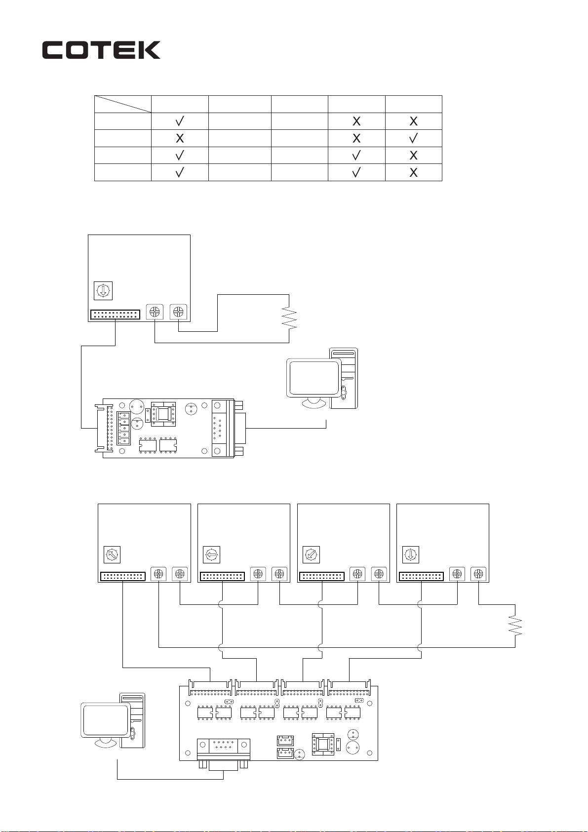
MODEL: CT-251 / 551 Parallel Control with Remote Sensing
1
+ +
-
CN2
+
-
DC OUTPUT
+
-
Load
+
-
CN2
J1
CN1
CN3
CN4
CN2
CN3
CN4
CN2
CN3
CN4
23
1
2
3
4
5
1
6
1
6
J1
CN1
123
1
2
3
4
5
1
6
1
6
J1
CN1
123
1
2
3
4
5
1
6
1
6
CN1
CN2
CN3
J1
1
5
CN4
6
9
123
1
2
3
4
5
1
6
-
MAX.8 EUT
*Last control board
J1 need short
MAX. 200M
CT
parallel cable
MAX. 200M
CT
parallel cable
MAX. 10M
MAX. 200mm
CT
series cable
MAX. 200mm
CT
series cable
MAX. 200mm
CT
series cable
MAX. 200mm
CT
series cable
RS485 RS485
CT-251CT-551CT-551CT-551
PC
4
0
7
6
5
3
2
1
CN2
DC OUTPUT DC OUTPUTDC OUTPUT
CN2 CN2
RS485 RS485 RS485 RS232
RS485
Programmable
Power Supply
Programmable
Power Supply
Programmable
Power Supply
Programmable
Power Supply
Before using RS232/485 to control COTEK programmable SMPS (excl. AK Series),
make sure to read the following notes:
1. Make sure the voltage and current setting has been correctly delivered to EUT before setting the
command (Power <type>) to turn on / off the power supply. If OVP, or OLP LED signal has been
activated due to incorrect operation, enter command POWER <type> will allow you to operate the
EUT and setting command.
2. Every RS232/485 command character must be entered within 400ms, the ending point is judged by
CR LF (0D0A), program will disregard the command if the command entering time exceeds 400ms
per character.
3. After shut-down of the power of EUT, command setting will return to default, local mode.
4. After power on the EUT with command execution complete, EUT will switch to remote mode with
orange LED signal status. For detail LED signal info, please refer to the EUT datasheet.
5. Please refer to the CT-xxx user manual (Page 02) for the cable spec. connect in between the CT-xxx
controller board and EUT. Make sure to connect the cable as instructed on the user manual to avoid
CT-xxx damage.
6. CT-xxx boards could support max. 8 units serial or parallel control function (ADDS 0-7). Before
controlling the EUT, make sure the address is not in conflict with each other.
7. When controlling multiple EUT’s, make sure to query the Address (ADDS x) first before entering
command to avoid EUT retrieving the incorrect value. If only single EUT, there is no need to query
ADDS before entering command.
No. 33, Rong Hsin Rd., Pa Teh City, Tao Yuan County, Taiwan
Phone : 886-3-3661581 FAX : 886-3-3676029
http : // www.cotek.com.tw
2013.04 A0
4
0
7
6
5
3
2
1
4
0
7
6
5
3
2
1
4
0
7
6
5
3
2
1
6
This manual suits for next models
4
Table of contents
Popular Recording Equipment manuals by other brands

CAME
CAME Security line CP Series Installer manual

Panasonic
Panasonic SVSR100 - SD AUDIO RECORDER operating instructions

Omega
Omega OM-CP-IFC200 Quick installation guide

PeakTech
PeakTech 1140 Operation manual

C. Crane
C. Crane VersaCorder operating instructions

Mutable Instruments
Mutable Instruments Links user manual