F
or
additional
information
email
[email protected]om or call 800-345-6007 M-F 8-5 CST4
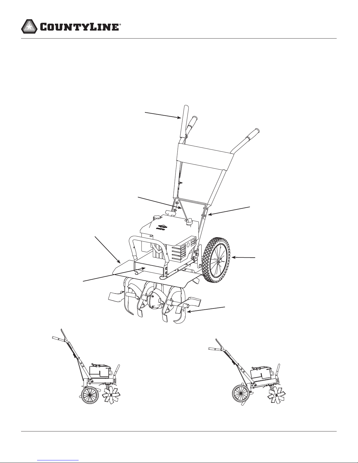
Operator’s Manual
17455 Front Tine Tiller
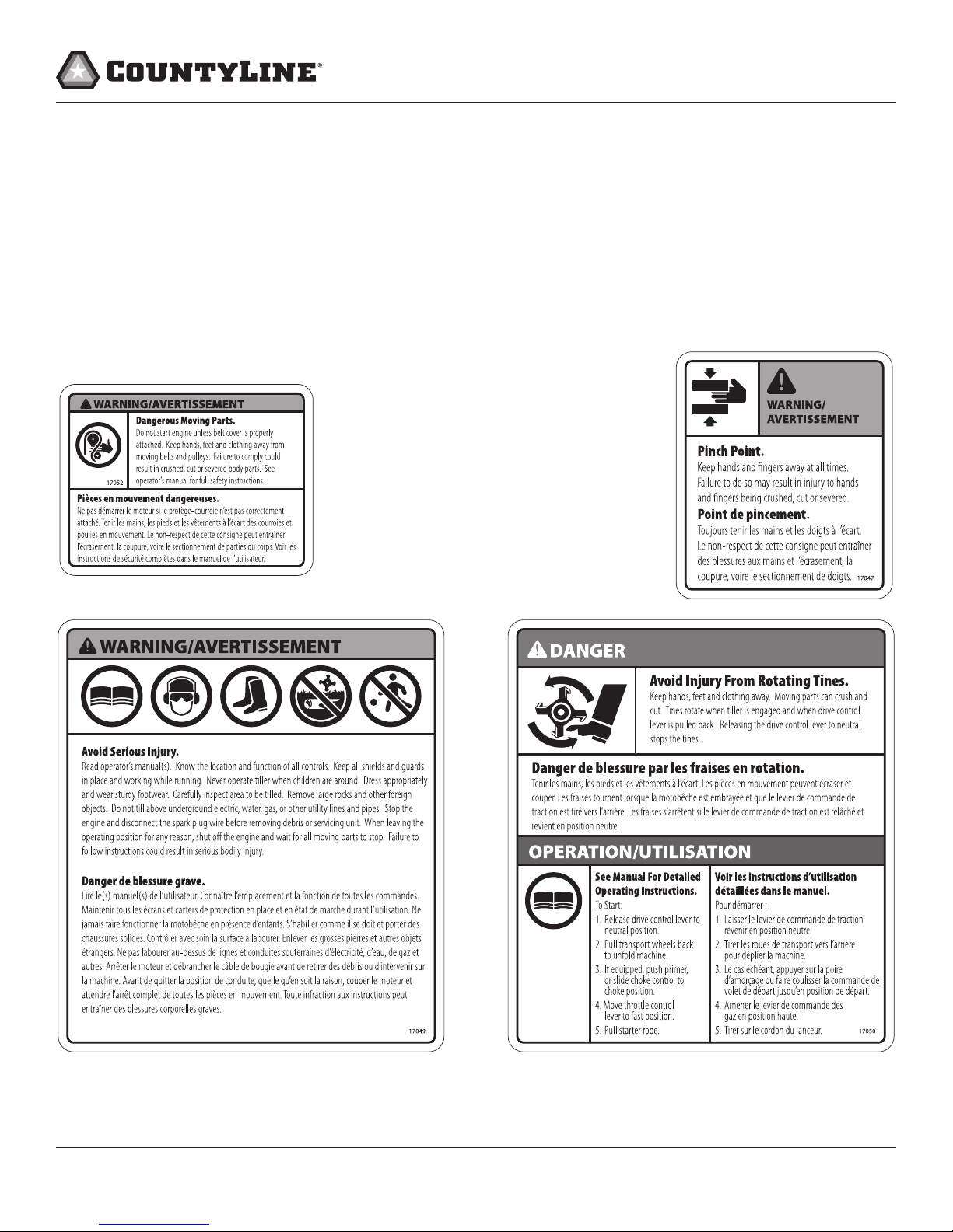
GENERAL SAFETY RULES
• Read, understand, and follow all instructions on the machine
and in the manual(s). Be thoroughly familiar with the controls
and the proper use of the machine before starting.
• Use this equipment for its intended purpose only.
• Familiarize yourself with all of the safety and operating
decals on this equipment and on any of its attachments or
accessories.
• Do not put hands or feet near or under rotating parts.
• Only allow responsible individuals who are familiar with the
instructions to operate the machine. Do not allow children
to operate this machine. Do not allow adults to operate the
machine without proper instruction.
• Thoroughly inspect the area where the machine is to be
used and remove all foreign objects. Your equipment can
propel small objects at high speed causing personal injury
or property damage. Stay away from breakable objects, such
as house windows, automobiles, greenhouses, etc.
• Wear appropriate clothing such as a long-sleeved shirt or
jacket. Also wear long trousers or slacks. Do not wear shorts.
Never wear sandals, sneakers or open shoes, and never
operate the machine with bare feet.
• Do not wear loose clothing or jewelry. They can get caught in
moving parts. Always keep hands, feet, hair and loose clothing
away from any moving parts on engine and machine.
• Always wear safety goggles or safety glasses with side shields
when operating the machine to protect your eyes from
foreign objects which can be thrown from the unit. Always
wear a protective hearing device.
• Always wear work gloves and sturdy footwear. Wear
footwear that will improve footing on slippery surfaces.
Leather work shoes or short boots work well for most people.
These will protect the operator’s ankles and shins from small
sticks, splinters, and other debris.
• It is advisable to wear protective headgear to prevent the
possibility of being struck by small ying particles, or being
struck by low hanging branches, twigs, or other objects
which may be unnoticed by the operator.
• Do not operate the machine without proper guards or other
safety protective devices in place.
• See manufacturer’s instructions for proper operation and
installation of accessories. Only use accessories approved
by the manufacturer.
• Operate only in daylight or good articial light.
• Do not operate product when fatigued or under the
influence of alcohol, drugs or other medication which
can cause drowsiness or aect your ability to operate this
machine safely.
• Never operate machine in wet grass. Always be sure of your
footing; keep a rm hold on the handle and walk; never run.
• Watch for trac when operating machine near, or when
crossing roads.
• If the equipment should start to vibrate abnormally, stop the
engine (motor), ip the ON/OFF switch to the OFF position.
Check immediately for cause.Vibration is generally a warning
of trouble. If the noise or vibrations of the machine increase,
stop immediately and perform an inspection.
• Never leave the machine unattended when the engine is
running. Flip the ON/OFF switch to the OFF position.
• Regularly inspect the machine. Make sure parts are not bent,
damaged or loose.
• Temperature of muer and nearby areas may exceed 150°
F (65° C). Allow muer and engine areas to cool before
touching. Never pick up or carry the machine while the
engine is running.
• Prolongedexposuretonoise andvibrationfromgasolineengine-
powered equipment should be avoided. Take intermittent
breaks and/or wear ear protection from engine noise as well as
heavy work gloves to reduce vibration in the hands.
• Keepallscrews,nutsandboltstight.
• Do not transport the machine from one place to another
with the engine running.
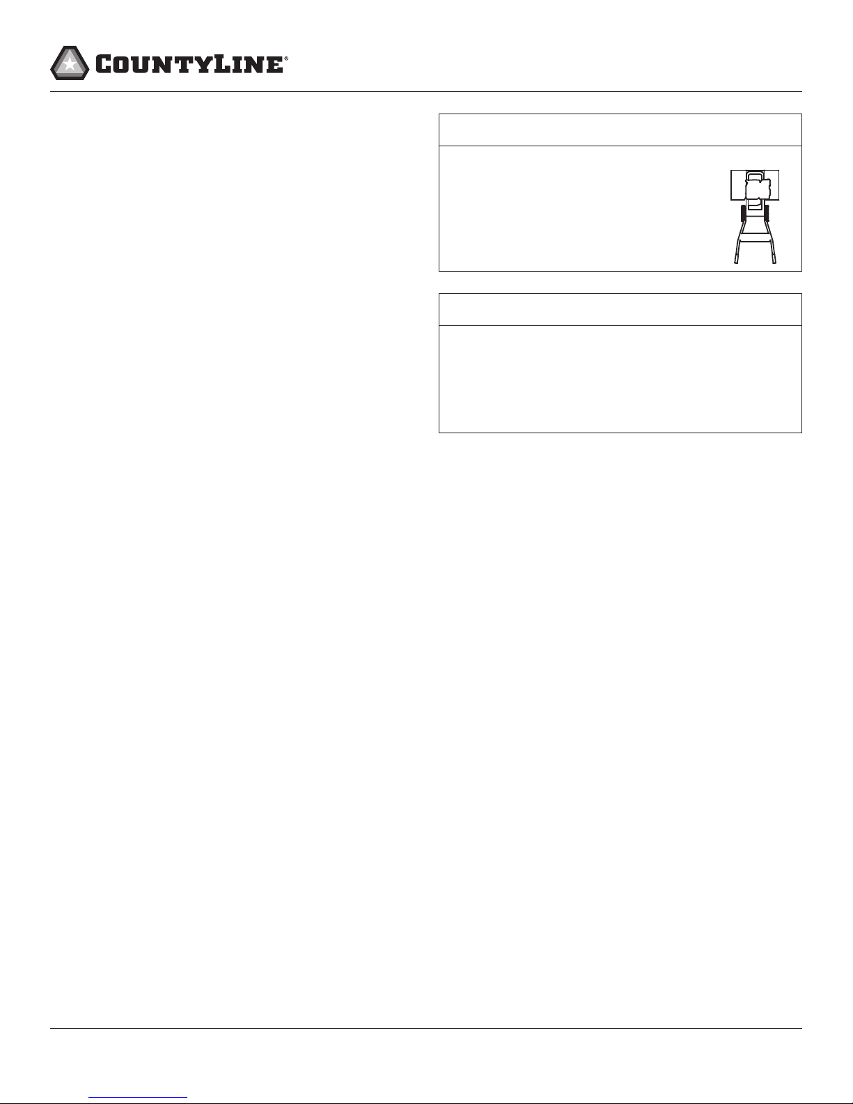
• When moving the packaged machine, always do so with a
partner.
• Check local regulations for age restrictions on use of this
machine.
PRODUCTSPECIFIC SAFETY RULES
• Do not till above underground utilities, including water
lines, gas lines, electric cables, or pipes. Do not operate the
machine on terrain/soil with large rocks and foreign objects
which can damage the equipment.
• After striking a foreign object, stop the engine. Flip the ON/
OFF switch to the OFF position. Inspect the machine for
damage. If damaged, repair before starting and operating
the machine.
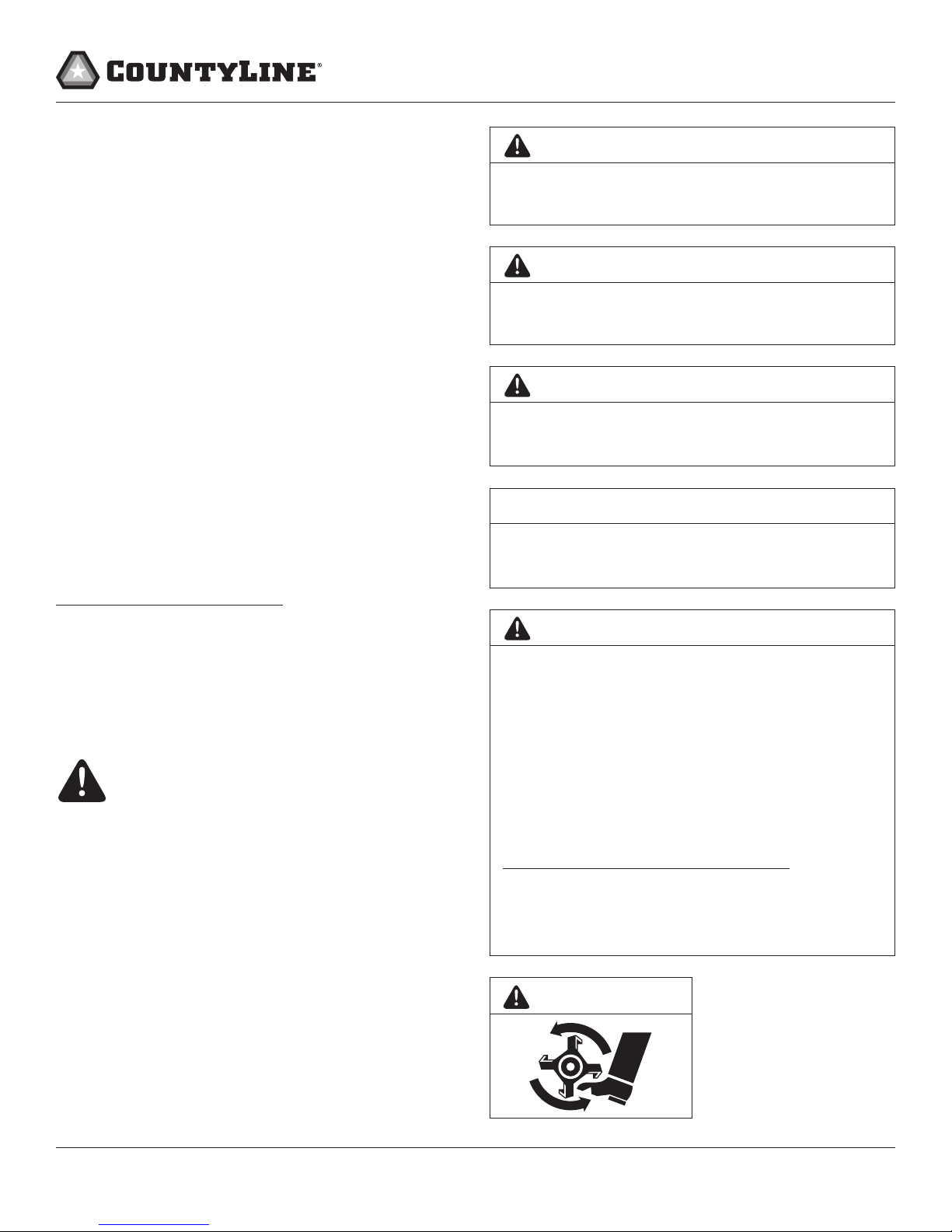
• The tines of the tiller should not rotate when the drive control
lever is released into the neutral position. If it does rotate
when in neutral, contact CountyLine customer service for
instruction.
• If an object becomes lodged in the tines, ip the ON/OFF
switch to the OFF position, allow to cool before attempting
to remove the foreign object.
• Pulleys and belts should be kept free of oil or other moisture
for ecient operation.
• Disengage all clutches and leave control lever in the neutral
position before starting the engine.