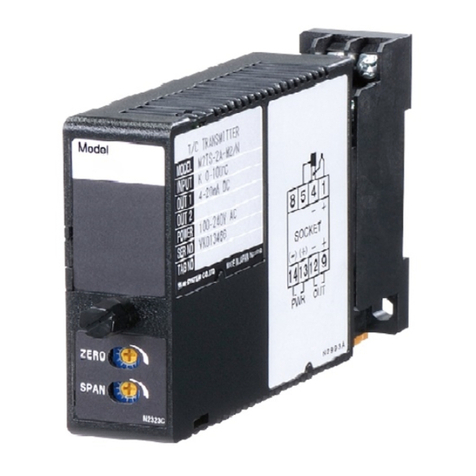
Cove Communications SILVERLINE VTx User manual

SILVERLINE VTX 03/09/08 User Guide Issue1 Page 1
User Guide
SILVERLINE VTx
Miniature Fibre Optic Video Transmitter
Serial Number ...............................................
Date Commissioned ......................................
Commissioned By ..........................................
Cove Communications
Contacts.........................................................
Cove Communications Ltd.
8 Copthorne Business Park,
Dowlands Lane,
Copthorne, Crawley,
West Sussex,
England
RH10 3HX
Tel: +44 (0) 845 838 8850
Fax: +44 (0) 1342 715384

SILVERLINE VTX 03/09/08 User Guide Issue1 Page 2
CONTENTS
1. INTRODUCTION
2. FEATURES
3. SPECIFICATION
4. ANALOGUE VIDEO DISTRIBUTION SYSTEMS
4.2 Levels and Impedance
4.3 Bandwidths
5. OPERATION
5.1 General
5.2 AGC (Automatic Gain Control)
6. INSTALLATION
6.1 Installation Records
6.2 External Use
6.3 Power Requirements
6.4 Power Connections and LED Indications
6.5 Fibre Optic Connection
6.6 Fibre Optic Cable
7. MAINTENANCE
8. FAULT DIAGNOSIS
1. INTRODUCTION
The SILVERLINE VTX Miniature Fibre Optic Transmitter has been designed for use with
composite colour and monochrome video signals that fall within the frequency bandwidth
of 15MHz. As all current terrestrial broadcasting standards such as PAL, NTSC and
SECAM require only 5.5MHz of bandwidth they are eminently suitable for transmission
over fibre with this product. This product enables high quality video distribution over fibre
without the need for equalisation for distances up to 4km.
Because of the wide bandwidth of the Cove Communications SILVERLINE Fibre Optic
Video Transmitter and its video encoding systems independence, users can be confident
when using this product that they are relatively future proof against the introduction of new
composite video standards and compatibility problems. However the extended bandwidth
of the Cove Communications SILVERLINE Fibre Optic Video Transmitter currently allows
its use with high quality video sources such as some high quality, high resolution cameras
and will give far superior results compared to the use of coaxial cable even for relatively
short distances. The extended bandwidth also ensures that the new 16 x 9 aspect ratio
wide screen video format, which has a bandwidth of 7.5 MHz may be used with this
product.

SILVERLINE VTX 03/09/08 User Guide Issue1 Page 3
This product is intended for use with multimode fibre and is available to order fitted with
either the ST or SMA fibre optic connectors. The Cove Communications SILVERLINE VTx
Fibre Optic Video Transmitter is intended for use with the range of Cove Communications
Fibre Optic Video Receivers. This range includes the SILVERLINE VRx miniature receiver
and the STARLINE 19 inch rack mountable range of receivers, VRX 1 Channel, VRX 2
Channel, and the VRX 3 Channel version.
The unit is constructed in a robust light weight housing and is fitted with a BNC video
connector intended for direct connection to video sources such as, cameras, video tape
recorders etc.
Power is connected to the unit via a miniature circular connector requiring a nominal +12v
D.C. supply.
To help during installation LED's are provided to indicate that the D.C. power is connected,
that video is present.
This equipment has been designed to meet the European EMC requirements.
2. FEATURES
Compact miniature metal case construction
Conforms fully to all world composite broadcasting standards (PAL, NTSC, SECAM)
Video composite encoding system independent
Up to 4km video distribution with multimode fibre optic cable
Suitable for colour and monochrome video systems
ST or SMA Optical connectors to order
Easy Installation
Connects directly to the video source
Low cost
Wide Bandwidth
Low Distortions
Transparent operation
Video present LED
Power connection indication LED
Internal DC Supply regulation
Optional mains power cube DC supply

SILVERLINE VTX 03/09/08 User Guide Issue1 Page 4
Separate DC supply connector for host powering
High efficiency optical emitter
Professional construction
Optical interface gives immunity to all electromagnetic interference
Total electrical isolation between sites with no earthing problems
Wide operating temperature range
3. SPECIFICATION
Video input Level: 1V p-p +3dB max (Composite)
Video Input (sync to video relationship): 0.3V syncs to 0.7V video
Video input Impedance: 75 Ohms
Bandwidth: Greater than 15MHz
Operating Distance (fibre) d.c to 15 MHz 4km ( with Cove Communications optical video receiver)
LED Indications: Power and video present
Light Source: LED
Light Source Wave Length: 850nm
Optical output power: Greater than 30µW (62.5 / 125 fibre)
Optical Connectors: ST
Construction: Metal Case
Overall Size: 71 x 63 x 30mm
DC Power Requirements: 11-15V at 70mA
Overall weight: 0.15kg
Operating Temperature: -5º C to +50º C
Storage Temperature: -20ºC to +70ºC
Humidity: 90% non-condensing
Cove Communications reserves the right to change the specification without notice

SILVERLINE VTX 03/09/08 User Guide Issue1 Page 5
4. ANALOGUE VIDEO DISTRIBUTION SYSTEMS
Apart from the normal terrestrial video broadcast systems; PAL, NTSC and SECAM the
Cove Communications SILVERLINE VTX Fibre Optic Video Transmitter may be used with
other distribution systems, provided that the signal has a composite format, i.e. it has a
mixed sync part to its waveform.
4.1 Levels and Impedance
The input impedance of the Cove Communications SILVERLINE VTX Fibre Optic video
transmitter is 75 Ohms. Should the application require a video looping facility, the
transmitter can be supplied with a high input impedance suitable for looping.
4.2 Bandwidths
The SILVERLINE VTX has a bandwidth that extends beyond 15MHz and over the
broadcast specified frequency response for PAL, NTSC and SECAM, when used in
conjunction with the Cove Communications Fibre Optic Video Receiver the frequency
response will be within ±1dB from D.C. to 5.5MHz.
5. OPERATION
5.1 General
The SILVERLINE VTX is intended for use with the range of Fibre Optic Video receivers.
This range includes the SILVERLINE VRX miniature receiver and the STARLINE 19 inch
rack mountable range of receivers, VRX 1 Channel, VRX 2 Channel, and the VRX 3
Channel version.
The video transmitter is small enough to be connected directly to the video source and
may either draw its power from the host equipment or from an external D.C. supply. The
video signal is processed in the analogue domain and converts the analogue video input
signal into a linearly modulated infra-red light source for transmission down the fibre optic
cable.
5.2 AGC (Automatic Gain Control)
The AGC (Automatic Gain Control) featured in the range of Cove Communications Fibre
Optic Video Receivers uses the mixed sync portion of the video signal to set the through
gain. If the mixed sync signal presented to the transmitter is 0.3V and the peak white level
is 0.7V then the output signal from the receiver will be the same. However, if the input
video mixed sync amplitude is low compared to the peak white level, at the transmitter the
video output level will be high from the receiver because the mixed sync level will be
amplified up to the standard 0.3V level. Conversely if the input mixed sync level is too high
compared to the peak white at the transmitter the output video level at the receiver will be
too low because the mixed syncs will be attenuated back to the correct 0.3V level. If the
amplitude relationship between the mixed syncs and the peak white video is correct at the
transmitter but happens to be overall either too high or too low the AGC in the receiver will
correct for this and output a perfectly correct signal.

SILVERLINE VTX 03/09/08 User Guide Issue1 Page 6
The AGC therefore offers to the installer many benefits provided that the video signal
presented to the transmitter has the correct sync to peak white video relationship.
The AGC fully compensates for the loss in the fibre optic cable and no amplification or
frequency response equalisation is required.
6. INSTALLATION
THIS EQUIPMENT IS NOT WATER PROOF AND MUST NOT BE USED OUTDOORS
UNLESS PROTECTED BY A CLIMATIC HOUSING.
THE FOUR SCREWS AROUND THE BNC CONNECTOR MUST NOT BE REMOVED
UNDER ANY CIRCUMSTANCES. THESE SCREWS DO NOT GIVE ACCESS TO THE
INSIDE OF THE UNIT.
6.1 Installation Records
NOTES
...........................................................................................................................................
...........................................................................................................................................
...........................................................................................................................................
...........................................................................................................................................
...........................................................................................................................................
...........................................................................................................................................
...........................................................................................................................................
...........................................................................................................................................
...........................................................................................................................................
...........................................................................................................................................
...........................................................................................................................................
...........................................................................................................................................
...........................................................................................................................................
...........................................................................................................................................
6.2 External use
If this fibre optic video transmitter is to be used with a video camera mounted in the open,
it should be fitted into the climatic enclosure along with the camera. If the video camera
has a pan tilt and zoom pedestal, it is recommended that the Video SILVERLINE is
mounted to a fixed position and a special flexible video coaxial cable used for the camera
connection. This is because fibre optic cable, although quite flexible, is not ideal for this
application as the specialised coaxial types.
6.3 Power Requirements
The video SILVERLINE may either be powered by the host equipment or from an external
12V D.C. supply.
The D.C. supply must be between 12 - 18V at 100mA. The connection is wired directly to
the power connector that is supplied as part of the unit or is available separately to order.

SILVERLINE VTX 03/09/08 User Guide Issue1 Page 7
6.4 Power Connections and LED indications
D.C. connector connections: Right........ Positive (+12 to + 18V D.C.)
Left........... 0V (Earth )
The 0V connection may be connected to earth if required.
A green LED is provided on the unit, which indicates that the D.C. power is connected.
6.5 Fibre Optic Connection
The video transmitters are supplied with either ST or other fibre optic connectors according
to the order. If no preference is stated the default connector will be the ST version.
6.6 Fibre Optic Cable
The transmitter will work with all multimode fibre optic cable. 50/125 and 62.5/125 fibre
optic cable is recommended.
7. MAINTENANCE
The unit has been designed for continuous running and fault free operation. Should the
unit require servicing it must be returned to Cove Communications, as there are no internal
customer serviceable parts.

SILVERLINE VTX 03/09/08 User Guide Issue1 Page 8
8. FAULT DIAGNOSIS
The Cove Communications Fibre Optic Video Transmitters can only be fully tested in
conjunction with a known working Cove Communcations Fibre Optic Video Receiver.
However the LED indicators will give a guide as to its operation
FAULT POSSIBLE CAUSE
Green LED 'OFF'. D.C. power not present at the circular D.C. connector.
Incorrect wiring of the circular D.C. connector (reverse
polarity connection may damage the unit).
D.C. voltage is too low. This should not be below +11v.
Green LED 'ON' but No video signal connected to the unit.
Yellow LED is 'OFF' Video signal level is non standard or too low in level.
Green and Yellow LED's Fibre optic cable loss is too high.
are 'ON' but there is no Dirt in fibre optic connectors or the level is low due to
video output at the receiver a faulty optic transmitter diode (return to Cove
Communications for service)
Green and Yellow LED's Mixed sync level at the transmitter is too high in
are 'ON' but the video output amplitude compared to the peak white level.
level at the receiver is low in (Ensure your video source signal is compatible)
amplitude.
Green and Yellow LED’s Mixed sync level at the transmitter is too low in
are ‘ON’ but the video output amplitude compared to the peak white level.
level at the receiver is high in
amplitude.
-END-
This User Guide has been produced by Cove Communications and may not be copied or
reproduced in any way shape or form without the written permission of Cove Communications.
Table of contents
