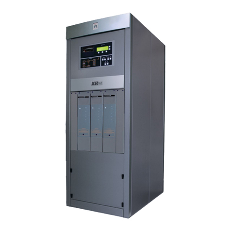
Nautel XR12 User manual

XR12 Transmitter
Operations and Maintenance
Manual
Document:NHB-XR12-OPS
Issue: 3.1 2013-03-14
Status: Standard

left blank intentionally

Nautel Limited
10089 Peggy’s Cove Road
Hackett’s Cove, NS Canada B3Z 3J4
Phone: +1.902.823.3900 or
Toll Free: +1.877.6NAUTEL (6628835) (Canada & USA only)
Fax: +1.902.823.3183
Nautel Inc.
201 Target Industrial Circle
Bangor, Maine USA 04401
Phone: +1.207.947.8200
Fax: +1.207.947.3693
Email: [email protected]
Web: www.nautel.com
The comparisons and other information provided in this document
have been prepared in good faith based on publicly available
information. The reader is encouraged to consult the respective
manufacturer's most recent published data for verification.
© Copyright 2009 NAUTEL. All rights reserved.

left blank intentionally

XR12 Operations and Maintenance Manual Table of contents
Page v
Contents
About this manual vii
About Safety xi
Electrical Hazards 3-xi
Lightning Hazards 3-xii
RF Hazards 3-xii
Toxic Hazards 3-xii
Other Hazards 3-xii
Safety Precautions xiii
Personal Safety 3-xiii
Site Safety 3-xiv
Equipment Safety 3-xvi
Description 1-1
Ac/dc power stage 1-1
Exciter stage 1-2
RF power stage 1-4
RF output filter 1-5
Control/monitor stage 1-6
Operating the transmitter 2-1
Graphic user interface 2-2
XR12 GUI 2-2
Viewing alarm status 2-7
Controlling power modules 2-8
Changing automation settings 2-9
Changing general settings 2-10

XR12 Operations and Maintenance Manual Table of contents
Page vi Issue 3.1 2013-03-14
Viewing digital meters 2-14
Setting the clock 2-16
Viewing software version information 2-19
Adjusting screen contrast 2-20
Changing hardware settings 2-20
Using the event log 3-1
Viewing the event log 3-1
Clearing the event log 3-6
Event log messages 3-7
Routine maintenance 4-1
Scheduled maintenance 4-1
Replacing air filter 4-2
Performing on-air checks 4-3
Replacing the control/display PWB battery 4-3
Inspecting lightning protection systems 4-4
Test and adjustment 5-1
Test equipment required 5-1
Test prerequisites 5-1
Standard adjustments 5-2
Non-standard adjustments 5-4
List of terms 6-1
Index IX-1

XR12 Operations and Maintenance Manual
Issue 3.1 2013-03-14 Page vii
About this manual
This manual provides technical information needed when operating, maintaining and
troubleshooting an XR12 transmitter. This manual is intended for use by transmitter operators and
field technicians.
Using this manual
If you are responsible for configuring or operating a transmitter, see Section 2, “Operating the
transmitter” on page 2-1 and Section 3, “Using the event log” on page 3-1.
If you are performing scheduled maintenance, or planning your maintenance schedule, see Section 4,
“Routine maintenance” on page 4-1.
If you are performing a test or adjustment, as instructed during a troubleshooting task, see Section 5,
“Test and adjustment” on page 5-1.
Performing procedures
When using procedures in this manual, perform each step in sequence.
• If you are asked to see another section of this manual, or another document, refer to that
section or document for additional information, then continue the procedure.
• If you are asked to go to another step within the procedure, jump directly to that step with-
out performing the intervening steps.
• If you are asked to go to another section or document, stop the procedure and perform the
tasks described in the other section or document.
• If you are asked to check a voltage, use a digital voltmeter and test the voltage relative to
ground (unless otherwise instructed).
• If you are asked to check a signal, use an oscilloscope and test the signal relative to ground
(unless otherwise instructed).

XR12 Operations and Maintenance Manual
Page viii Issue 3.1 2013-03-14
Technical support
Nautel offers technical support to customers over the Internet and by telephone. Nautel’s customer
support team will answer your questions and work with you to identify and resolve problems.
For technical support, call the Customer Support Team at 902-823-3900 or - in U.S.A. and Canada
only - call toll free at 1-877-6NAUTEL (662-8835). Or find us on the Internet at http://
www.nautel.com.
For parts and tools information, see “Parts and tools” on page 9-1 of the XR12 Pre-Installation Manual.
For accessories or spares, see “Accessories” on page 10-1 of the XR12 Pre-Installation Manual.
For standard warranty information, see “Pre-installation assistance” on page 11-1 of the
XR12 Pre-Installation Manual.
For extended warranty information, see “Pre-installation assistance” on page 11-1 of the
XR12 Pre-Installation Manual.
XR12 transmitter manuals
The XR12 documentation suite includes the following documents:
XR12 Pre-installation Manual, XR12-PREINST. The Pre-installation Manual provides
instructions and reference information needed when planning and preparing for the installation of an
XR12 transmitter.
Nautel Site Protection Manual. The Site Protection Manual provides detailed information
about protecting your site from lightning-related hazards.
CAUTION: FAILURE TO COMPLY WITH RECOMMENDATIONS MAY VOID YOUR
MANUFACTURER'S WARRANTY. FOR MORE INFORMATION, REVIEW YOUR
WARRANTY DOCUMENTS.
Tip: When you have completed a task or a step, put a checkmark beside the step number.

XR12 Operations and Maintenance Manual
Issue 3.1 2013-03-14 Page ix
XR12 Installation Manual, XR12-INST. The Installation Manual provides instructions and
reference information needed when installing an XR12 transmitter.
XR12 Operating and Maintenance Manual, XR12-OPS-MAINT. The Operating and
Maintenance Manual provides instructions for operating, maintaining and troubleshooting
an XR12 transmitter. It also provides reference information needed when performing diagnostic
procedures.
XR12 Troubleshooting Manual, XR12-TROUBLE. The Troubleshooting Manual provides
detailed technical information about the XR12 transmitter, including electrical schematics and
mechanical drawings.
Nautel website / Online resources
The Nautel website provides useful resources to keep you up to date on your XR12.
Nautel User Group (NUG)
The website includes a special section that customers can log into in order to access the Nautel
customer newsletter, product manuals, frequently asked questions (FAQ), information sheets, and
information about field upgrades. Registration is available online and is required.
Documentation: online and printed
The website’s NUG section provides online access to all the documentation for your XR12.
Documentation is provided in Acrobat (PDF) format. You can use the documentation online or
print the sections that you need.
When using online documents:
• Click on blue text (hyperlinks) to jump to a related section, or to get additional information
(e.g., view a term’s definition).
• To search a document to find keywords, use Find in Acrobat Reader’s Edit menu.
• To quickly find a specific section, click the section in the PDF file’s Bookmarks list.
When using printed documents:
• To find keywords, go to the Index section at the end of the manual.
• To find a specific term, go to the List of Terms section near the end of the manual.
XR12 Operations and Maintenance Manual
Page x Issue 3.1 2013-03-14

XR12 OPERATIONS AND MAINTENANCE MANUAL
VERSION 3.1 2013-03-14 PAGE XI
About Safety
All Nautel transmitters are designed to meet the requirements of EN60215, Safety Requirements for
Radio Transmitters. The philosophy of EN60215 is that the removal of any cover or panel that can only
be opened using a tool is a maintenance activity, and that any person performing a maintenance
activity is expected to be trained for that activity. Under EN60215, it is assumed that trained personnel
will be knowledgeable and will take precautions such as removing all power to the transmitter before
accessing its components.
Electrical Hazards
To remove power from the transmitter, switch off and lock out the ac power. There are three amber
LEDs at the bottom rear of the cabinet that glow to remind anyone who has not turned off the power
that the system is live and serious danger is present.
DANGER - HIGH VOLTAGE
Indicates dangerous voltage (in excess of 72 volts), capable of causing a fatal
electrical shock, are present on or near parts bearing this label.
Mount the transmitter ac power disconnect switch/breaker close to the transmitter so that it can be
reached quickly in an emergency. Clearly label the switch/breaker (e.g., EMERGENCY SWITCH).
After turning off the power, always perform a measurement to confirm that the power is off before
touching anything within the transmitter. If the wrong breaker was opened, the equipment will be live.
Use only a non-contact voltage probe or a safety voltmeter (available from vendors such as Fluke, Ideal,
and Teagam).
Use a proper lockout procedure to ensure that another worker cannot accidentally reapply power while
you are performing maintenance on any part of the transmitter or site.
WARNING: IT IS NOT ENOUGH TO SWITCH OFF RF POWER. THE POWER LINE
IS STILL CONNECTED. DISCONNECT AND LOCK OUT THE UPSTREAM SUPPLY
BEFORE SERVICING.
WARNING: DO NOT USE AN ORDINARY MULTIMETER TO CHECK FOR
VOLTAGE, SINCE IT MAY HAVE BEEN LEFT INADVERTENTLY ON THE AMP (A)
RANGE, TRIGGERING A SHORT AND AN ARC BLAST THAT COULD RESULT IN
SEVERE BURNS AND EVEN DEATH.

XR12 OPERATIONS AND MAINTENANCE MANUAL
PAGE XII VERSION 3.1 2013-03-14
Lightning Hazards
Before opening the transmitter and touching internal parts, remove and solidly ground the antenna
connection.
RF Hazards
A serious RF hazard and very high voltages exist in the vicinity of the antenna and its networks during
normal operations.
Toxic Hazards
There are devices used in this equipment containing beryllium oxide ceramic, which is non-hazardous
during normal device operation and under normal device failure conditions. These devices are
specifically identified with “(BeO)” in the Description column of the Troubleshooting Manual’s parts
list(s).
Do not cut, crush or grind devices because the resulting dust may be hazardous if inhaled.
Unserviceable devices should be disposed of as harmful waste.
Other Hazards
Ensure that appropriate fire alarms and fire extinguishers are available. Extinguishers must be suitable
for use on electrical fires.
Many other site safety risks exist. It is beyond the scope of this manual to identify all the risks and
procedures.
WARNING: IT IS NOT ENOUGH TO GROUND THE ANTENNA TERMINAL WITH
THE ANTENNA STILL CONNECTED. EVEN A SMALL IMPEDANCE IN THE
GROUND STRAP WILL RESULT IN LETHAL VOLTAGES DURING A LIGHTNING
STRIKE.

XR12 OPERATIONS AND MAINTENANCE MANUAL
VERSION 3.1 2013-03-14 PAGE XIII
Safety Precautions
This section provides very important information about protecting the safety of personnel and
equipment:
Personal Safety - see page xiii
Site Safety - see page xiv
Equipment Safety - see page xvi
Personal Safety
Training
The training of any personnel who will have physical access to the site or the transmitter is very
important. Personnel must be familiar with the transmitter, so that they can avoid physical danger, and
be aware of hazards to themselves and the equipment.
Nautel offers a number of training courses covering the basic fundamentals of RF systems and
transmitters, and the operation and maintenance of the transmitter. For more information about
available courses and schedules, go to the Nautel website at http://www.nautel.com/Training.aspx, or
ask your Nautel sales representative.
Site Orientation
When you give personnel access to the transmitter site (e.g., hiring new personnel, or giving access keys
to personnel), perform a site orientation to ensure that they are familiar with the site, on-site
procedures, and on-site hazards. Cover the following topics:
Securing the site (locking doors and fences) to prevent unauthorized access
How and when to call for technical support or emergency assistance
Areas of the site and pieces of equipment that are off limits

XR12 OPERATIONS AND MAINTENANCE MANUAL
PAGE XIV VERSION 3.1 2013-03-14
Voltage Awareness
Ensure that all personnel that are able to access areas with high voltage circuits or high field strengths
are aware of the hazards associated with high voltage. Cover the following topics:
High voltage or high field strength areas where caution is required
Physical risks of electric shock
Risks for personnel with pacemakers or other medical implants
Induced voltages in high field strength areas
On-site risks during thunderstorms and lightning strikes
Operation of safety interlocks (if installed)
First Aid
Nautel does not offer first aid training, since the hazards associated with high voltage and RF energy
are not specific to the transmitter. However, the customer should provide first aid training to all
personnel who have access to the transmitter site. First aid training should include CPR, care of burns,
artificial respiration, and defibrillation if specific equipment is available on-site.
Site Safety
Controlling Access
Transmitters and antennas generate and carry dangerous voltages that can be harmful or fatal. It is very
important that you control access to the site and its equipment. To secure your transmitter site, use:
Locking steel or security doors to prevent casual access
A perimeter fence to keep trespassers away from the antenna system and feedline
“No Trespassing” signs
An alarm system

XR12 OPERATIONS AND MAINTENANCE MANUAL
VERSION 3.1 2013-03-14 PAGE XV
Marking Hazards
Place warning signs close to any hazardous areas or systems (e.g., the feedline or the antenna system).
Make the signs large enough that they cannot be missed. Provide signage in all languages used in the
region. These signs are intended not only for authorized personnel, but also for emergency responders
or accidental trespassers.
Qualifying Site Personnel
Make sure that personnel who have access to the site are qualified to work around electronics and high
voltage systems.
Ac Power Protection
You should take steps to protect equipment from surges (over-voltage spikes) on the ac power lines.
Surges may occur during thunderstorms, or because of malfunctions in the electrical distribution grid.
Surge suppressors and ac power conditioners can prevent serious damage to your on-site equipment,
including the transmitter.
RF Protection
Transmitters and their antenna systems create intense radio frequency fields at the transmitter site,
particularly near the feedline, antenna and tower. At some sites, these fields may cause biological
effects, including the heating of body tissues. Intense fields can also create dangerous high voltages on
ungrounded, conductive surfaces and objects. At certain points where high voltage conductors come
close to grounded conductors (e.g., at feedline junctions or on the tower), dangerous electrical arcing or
overs can occur. It is very important that you take the following steps to prevent damage to equipment
or personnel due to RF fields:
Use safety interlocks to de-energize transmitters if personnel open doors or panels accessing high
field areas
Place warning signs in any locations where high fields can occur
Train personnel about the short-term and long-term hazards of RF radiation
Physically block access to the area around the antenna system, feedline and tower
Ground all exposed conductive surfaces or objects in high field areas
The RF connection to the transmitter output can be a serious safety hazard. Connect a 50 Ωtest load
during installation and commissioning. It is recommended that a switch be used to automatically
connect the transmitter to the antenna system without human contact with the transmitting
conductors.

XR12 OPERATIONS AND MAINTENANCE MANUAL
PAGE XVI VERSION 3.1 2013-03-14
Safety Interlocks
The transmitter contains an electrical interlock, which is an external circuit that turns off the RF output
if any of its switches are opened.
Ac Disconnect Switch
Safe operation of the transmitter requires an ac disconnect switch. Lock the ac disconnect switch in the
disconnected (open) position during the installation process.
Equipment Safety
Electrostatic Protection
The transmitter’s systems are very rugged and resistant to damage. However, it is possible for damage
to occur because of high voltage electrostatic discharges during servicing. Train all service personnel to
ground themselves to bleed off any static charge before opening the transmitter or touching any
exposed components. Provide a grounding wand or known ground (e.g., a grounded metal table) that
personnel can use to discharge themselves.
Surge Protection
Surge protection is recommended for your entire site. However, even if you do not use a surge protector
on the service entrance to the site, you should install a surge protector in the transmitter’s ac power
feed to prevent over-voltage from entering the transmitter.
Lightning Protection
The transmitter is designed to resist lightning strike damage. However, intense or repeated strikes could
damage the transmitter. We recommend that you install lightning suppression on the antenna, tower
and feedline to reduce the effect of lightning strikes on the transmitter itself (and to protect the rest of
your site equipment and your personnel). For detailed information about lightning protection, see the
Nautel Site Preparation Manual, available from your Nautel sales agent, or online from the Nautel
website.

XR12 OPERATIONS AND MAINTENANCE MANUAL
VERSION 3.1 2013-03-14 PAGE XVII
Physical Protection
Consider physical hazards to equipment at your site, including the transmitter. Ensure that equipment is
protected from weather (e.g., rain or flooding), even during extreme weather events. Place equipment
so that it is not in the path of swinging doors or high-traffic areas. Do not allow wheeled items like
office chairs or tables with wheels in the transmitter room, as these may damage equipment if
accidentally pushed or knocked over. Do not place the transmitter under water pipes, drains, or
sprinklers. Keep any equipment that generates heat, like the transmitter, away from flammable
materials like ceiling panels, cubicle dividers, and curtains.
Earthquake Protection
If the transmitter site is in a region that experiences any noticeable earthquake activity, take steps to
prevent the transmitter from shifting or rocking during an earthquake. Even during minor earthquakes,
rocking or movement of the transmitter is likely to damage the feedline connection, and could even
cause a catastrophic failure of the ac power feed into the transmitter. During larger earthquakes, the
weight of the transmitter chassis could be hazardous to nearby equipment or personnel.

XR12 OPERATIONS AND MAINTENANCE MANUAL
PAGE XVIII VERSION 3.1 2013-03-14

XR12 Operations and Maintenance Manual Description
Issue 3.1 2013-03-14 Page 1-1
Section 1: Description
Refer to the functional block diagram: “XR Series Transmitter Block Diagram” on page 1-7.
This section provides a high-level description of the transmitter’s key sections. The transmitter
circuitry is subdivided into five basic stages:
• Ac/dc power stage
• Exciter stage
•RFpowerstage
• RF output filter (includes combiner)
• Control/monitor stage
XR12 electrical schematics
The descriptions in this section all refer to the XR12 electrical schematics located at the end of the
XR12 Troubleshooting Manual.
Redundancy
The XR12 features redundancy in all key systems:
• RF power modules (optional fully redundant backup is available)
• Exciters
• Cooling fans
Ac/dc power stage
See electrical schematic SD-3. The ac/dc power supply stage contains the input power transformer
that receives the main ac input to the transmitter. It also contains the transmitter’s low voltage power
supplies. The ac/dc power supply stage also include a three-phase voltage rectifier, Hall Effect
current sensor and B+ power supply/distribution PWB.
The output of the rectifier is fed through the Hall Effect current sensor, which supplies a dc current
signal to the distribution PWB. The distribution PWB provides a dc current sample to the control/
display PWB.

XR12 Operations and Maintenance Manual Description
Page 1-2 Issue 3.1 2013-03-14
The rectifier output is also applied to the B+ distribution PWB, which then provides the B+ voltage
to the RF power module and LVPS power supplies, and a B+ sample to the exciter interface PWB.
Voltages from the low voltage power supplies are then supplied throughout the transmitter.
Ac power transformer
The XR12’s power transformer can be set to use a range of input voltages. See Section 3, “Installing
the power transformer” on page 3-1 in the XR12 Installation Manual.
Exciter stage
See electrical schematics SD-1, SD-2 and SD-3 and Figure 1.1 on page 1-3. The exciter stage consists
of an exciter interface PWB (A2A1), RF synthesizer PWBs A (A2A2) and B (A2A4), interphase PDM
driver PWBs A (A2A3) and B (A2A5), distribution PWB (A16), and RF drive buffer PWB (A24). The
exciter stage contains two independent exciter sections (A and B), which can be selected automatically
or by local or remote control.
Exciter Interface PWB
The exciter interface PWB (A2A1) accepts audio from the remote interface PWB, carrier reference,
exciter selection, reset, and inhibit controls from the control/monitor stage. It also receives low-level,
regulated dc voltages and a B+ sample from the ac/dc power stage, and a sample of the PA volts
from the RF power stage. Each exciter section generates its own RF frequency source, PDM and
digital control signals, for use in the RF power stage. The exciter interface PWB passes signals to the
RF drive buffer PWB, which then outputs the RF drive signals to the RF power module in the RF
power stage
The exciter interface PWB also provides physical interconnection for the RF synthesizer PWBs (A
and B), and interphase PDM driver PWBs (A and B).
Other manuals for XR12
3
Table of contents
Other Nautel Transmitter manuals

Nautel
Nautel NX100 User manual

Nautel
Nautel NV7.5 User manual

Nautel
Nautel GV30N Programming manual

Nautel
Nautel NX5 Manual

Nautel
Nautel XR6 Programming manual

Nautel
Nautel ND500II Manual

Nautel
Nautel VS300 Programming manual

Nautel
Nautel NX100 User manual

Nautel
Nautel ND500II-113-x21 User manual

Nautel
Nautel NV10LT User manual

Nautel
Nautel VS1 User manual

Nautel
Nautel GV20 User manual

Nautel
Nautel NX200 User manual

Nautel
Nautel Vector-LP VR125 Owner's manual

Nautel
Nautel ND500II Manual

Nautel
Nautel XR6 User manual

Nautel
Nautel GV10 Programming manual

Nautel
Nautel ND500II User manual

Nautel
Nautel NX5 AM User manual

Nautel
Nautel GV10 User manual