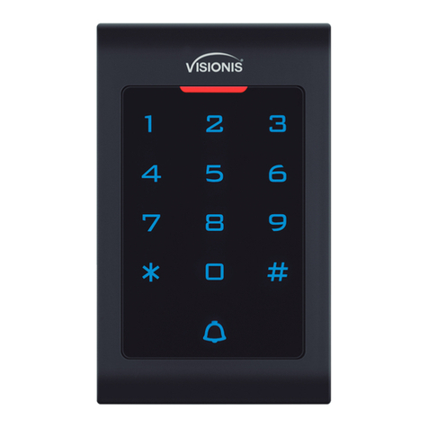
Cover Pools Coverlink Wireless Control User manual

600568 Rel-0006
1 of 7
The CoverLink Wireless Control system controls access to pool cover operation. The CoverLink Wireless Control
uses a Personal Identication Number (PIN) in place of a Key. Entering a valid PIN into the Control Pad allows
access to the cover and uncover operation for the pool cover.
COVERLINK WIRELESS CONTROL FEATURES
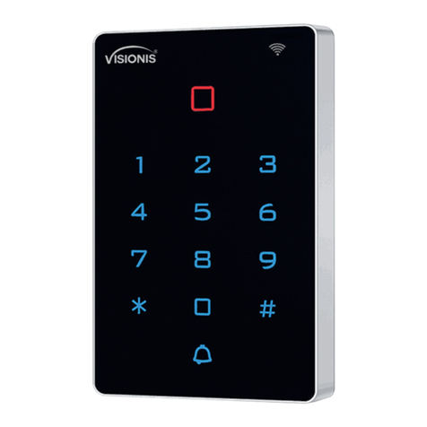
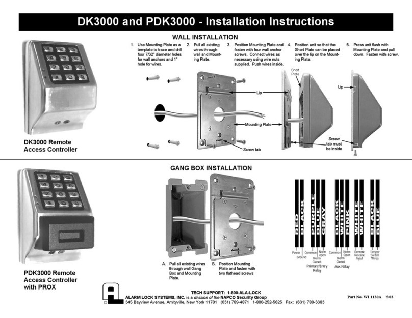
CoverLink Control Pad and CoverLink Receiver
The CoverLink Control system is factory programmed and ready for use.
THE CONTROL PAD MUST BE MOUNTED IN FULL VIEW OF THE POOL COVER.
Control Pad features:
• Up to 3 separate Control Pads can operate the same pool cover.
• Up to 4 unique 4 digit PINs can control access to the pool cover.
• Control Pads can be setup in different locations around the pool.
• A Master PIN that is stored in memory location 1 (Factory Default Master PIN: 1583).
• Additional PINs can be stored in memory locations 2, 3 and 4.
(The pool owner should keep a record of PIN to memory location, for reference).
• A unique signal that is sent from the Control Pad and stored by the Receiver when linked.
• Each Control Pad must be linked to the Receiver and set to:
»The same channel number and the same network ID number
Receiver features:
• 3 control buttons: • 32 usable Channels: • 100 Network ID numbers:
»Uncover »00 - 31 »00 - 99
»Cover
»Setup
• Typically the Receiver and Auto Shutoff board are located in an enclosure by the pool cover
electric motor.
CoverLink Control Pad
Green
LED Red
LED
Antenna Wire
Connection
CoverLink Receiver
Green LED
Red LED
Setup
UnCover
Cover
Red
Black
Green
Yellow
YELLOW
RED
BLACK
BLUE
WHITE
ORANGE
WHITE
Auto Shutoff to CoverLink Receiver
Green
LED's
YELLOW
GREEN
BLUE
ORANGE
BLACK
PURPLE
BROWN
RED
BLACK
AUTO SHUTOFF
AMP LIMIT
AMP
LIMITER
(LOW VOLTAGE WIRES)
(HIGH VOLTAGE WIRES)
Setup
Uncover
Cover
Instructions
Coverlink™ Wireless Control
Operation and Programming
©Cover-Pools Inc.
1-800-447-2838
1 of 7
600568 Rel-0006
Electrical Details 7:19

600568 Rel-0006
1. NORMAL OPERATION
1.1 Normal use: Control Pad
PIN entry controls access to the cover and uncover operation for the pool cover. After PIN entry, press &
hold 'C' or 'U' within 20 seconds or system will time-out and PIN re-entry is required.
1.1.1 Enter 4 digit PIN: 1583 (or valid PIN)
a.Red LED will ash as each button is pressed.
b. Green LED will ash if PIN is accepted.
Press & Hold C (Cover) or U(Uncover) to cover or uncover the pool.
c. Green LED will ash while cover is in motion.
If PIN is not accepted Red LED is "ON" when C (Cover) or U (Uncover) is pressed, re-enter PIN.
1.2 Normal use: Receiver (located in an enclosure with the Auto Shutoff board).
The Receiver buttons are intended for service use only.
Uncover = Uncovers the pool.
Cover = Covers the pool.
Setup = Use setup to reset to factory default (See RECEIVER RESET).
Use setup to re-link Control Pad and Receiver (See LINK CONTROL PAD AND RECEIVER).
2. PIN SETUP
Factory Default Master PIN: 1583. The Factory Default Master PIN CAN be changed.
The Factory Default Master PIN is stored in memory location 1 on the Control Pad and CAN be changed
to any 4 digit PIN.
This Master PIN controls access to add, change or delete PINs.
Service Master PIN: 2838. The Service Master PIN CAN NOT be changed.
The Service Master PIN is intended for service use only and CAN NOT be changed.
The Service Master PIN overrides all PINs and allows service to access all modes.
2.1.Change or Enter New PIN:
To change or enter new PINs follow this process. Buttons must be pressed within 20 seconds of
each other or programming access will time-out.
2.1.1. Enter '1583' (or valid PIN)
a. Red LED will ash as each button is pressed.
b. Green LED will ash if PIN is accepted.
2.1.2. Press 1 to enter programming mode.
a. Red and Green LED "ON".
2.1.3. Press 1 to enter PIN change mode.
a. Green LED will ash.
2.1.4. Press 1, 2, 3 or 4 to select PIN memory location.
(Remember Factory Default Master PIN is stored in memory location 1, but can be changed).
a. Red LED will ash.
2.1.5. Enter new 4 digit PIN.
a. Both LEDs will ash
(If you wish to abort PIN setup - press 0)
2.1.6. Enter new PIN again to conrm change.
a. Red LED will ash.
b. Green LED "ON" indicating success.
c. System is ready after 20 sec. delay and Green LED is "OFF".
Test new PIN by following NORMAL OPERATION.
2 of 7
Location # PIN
1 (1583)
2
3
4
PIN Memory Location Record
©Cover-Pools Inc.
2 of 7
600568 Rel-0006
Electrical Details 7:20

600568 Rel-0006
3. DELETE PIN
3.1.Delete PIN (except master):
To erase one PIN at a time from the Receiver follow this process. Buttons must be pressed within 20
seconds of each other or Programming access will time-out.
3.1.1. Enter '1583' (or current Master PIN)
a. Red LED will ash as each button is pressed.
b. Green LED will ash if PIN is accepted.
3.1.2. Press 1 to enter programming mode.
a. Red and Green LED "ON".
3.1.3. Press 2 to enter PIN delete mode.
a. Green LED will ash.
3.1.4. Press (2, 3, or 4) to delete PIN from that memory location.
a. Green LED will ash.
(If you wish to abort PIN Delete - press 0)
3.1.5. Press (2, 3, or 4) again for conrmation.
a. Green LED "ON" after brief delay indicating success.
b. System is ready after 20 sec. delay and Green LED is "OFF".
3.2.Delete all PINs (except master):
To erase all PINs except master from the Receiver follow this process. Buttons must be pressed
within 20 seconds of each other or Programming access will time-out.
3.2.1. Enter '1583' (or current Master PIN)
a. Red LED will ash as each button is pressed.
b.Green LED will ash if PIN is accepted.
3.2.2. Press 1 to enter programming mode.
a. Red and Green LED "ON".
3.2.3. Press 3 to enter all PIN delete mode.
a. Red and Green LED will ash.
(If you wish to abort PIN Delete - press 0)
3.2.4. Enter master PIN to verify delete.
a. Green LED "ON" after brief delay indicating success.
b. System is ready after 20 sec. delay and Green LED is "OFF".
4. RECEIVER RESET
Reset Receiver to factory default: (See Illustration on page 1 for Setup button location)
This process may require more than one person if Main Power (Breaker) is not within reach of Receiver.
To erase the Receiver memory including all linked Control Pads follow this process.
• All Control Pads must be re-linked to Receiver and PINs re-established.
(See LINK CONTROL PAD AND RECEIVER to reestablish link).
Verify Board Revision before proceding (located on Receiver Label)
For Revisions up to 5
4.1. Turn power "OFF" for 10 sec.
4.2. Hold Setup button down while turning power "ON".
The Green LED on the Receiver will ash briey indicating the erasure is complete.
For Revisions 5+ or higher
4.3. Push and release Setup button. Wait for red LED to go out.
• The Receiver is returned to factory default setting.
3 of 7 ©Cover-Pools Inc.
3 of 7
600568 Rel-0006
Electrical Details 7:21

600568 Rel-00064 of 7
Prior to programming the CoverLink System complete the following steps at the Autoshut Off Board and
Coverlink Receiver:
Uncover and cover the pool completely by pushing the buttons on the CoverLink Receiver located in the
Autoshut Off Box as shown on page 1 in illustration CoverLink Receiver.
If the operation of the cover is sluggish or stopping adjust the "amp limiter located on the Autoshut Off Board
as described in document #600356 WIRING AUTOSHUTOFFAMP LIMIT BRD-ACCB-AMP LMT LED FUNC.
5. LINK CONTROL PAD AND RECEIVER
This process may require more than one person if Control Pad is not within reach of Receiver. Buttons must
be pressed within 20 seconds of each other or Programming access will time-out.
Step 1
Enter Setup Mode:
1. Control Pad: Press and Hold U (Uncover) and 3until both LEDs turn "ON" (5 sec.).
2. Enter 396207 (6 digit Security code)
a. Control Pad: Red LED "OFF" - Green LED "ON".
Step 2
Link Radio Signal:
3. Receiver: Press and Hold the Setup button.
a. Receiver: Red LED "ON".
4. While Holding the Setup button on Receiver Press and Release 1 on the Control Pad.
a. Control Pad: Green LED will ash once then "ON" indicating link is established.
b. Control Pad: Red LED "ON" then Link is not established repeat 4.
(If your wish to abort Setup - press 4)
Step 3
Set Channel Number:
5. Press 2 to enter Channel mode.
a. No LEDs "ON".
6. Enter 2 digit Channel Number (00 - 31). (Example: 08)
a. Control Pad: Green LED "ON" if Channel is accepted.
b. Control Pad: Red LED "ON" if Channel is not accepted, repeat 5 and 6.
Step 4
Set Network ID Number:
7. Press 3 to enter Network mode.
a. No LED's "ON".
8. Enter 2 digit Network ID Number (00 - 99) (Example: 09).
a. Control Pad: Green LED "ON" if Network ID is accepted.
b. Control Pad: Red LED "ON" if Channel is not accepted, repeat 7 and 8.
Step 5
End Setup:
9. Press 0 on Control Pad.
a. Control Pad: Green LED will ash once if accepted.
Link is complete and system is ready for normal operation.
(See NORMAL OPERATION and PIN SETUP)
b. Control Pad: Red LED "ON" if Link is not accepted, wait 20 seconds and repeat Link
procedure.
©Cover-Pools Inc.
4 of 7
600568 Rel-0006
Electrical Details 7:22

600568 Rel-00065 of 7
PROBLEM SOLUTION
LEDs on Control Pad do not light when
buttons are pressed.
Did not x problem.
Remove Control Pad faceplate.
Remove batteries from battery holder.
Clean battery contacts.
Install new batteries in battery holder.
Reinstall Control Pad faceplate.
Contact local Cover Dealer for service.
PIN entry does not activate Cover
Mechanism, but red LED on Control
Pad is 'ON' when buttons are pressed.
Did not x problem.
Did not x problem.
Power "ON" toAuto Shutoff board
Did not x problem.
Did not x problem.
Enter valid PIN.
If PIN is Valid, Green LED will ash as C (Cover) or U (Uncover) is
pressed.
If PIN is NOT valid, Red LED is 'ON' as C (Cover) or U (Uncover) is
pressed, Re-enter PIN.
Verify that power to the Auto Shutoff board is on.
Typically the Auto Shutoff board and Receiver are located in an enclo-
sure by the pool cover electric motor.
Power to Auto Shutoff board is on if 2 Green LEDs on Auto Shutoff
board are ashing. (see Illustration on page 1).
Turn power "OFF" for 10 sec.
Turn power "ON".
Enter valid PIN.
See RECEIVER RESET instructions. (pg. 3)
See LINK CONTROL PAD AND RECEIVER instructions. (pg. 4)
Contact local Cover Dealer for service.
Coverlink™ Wireless Control
Troubleshoot Guide
ExPLANATION OF CHANNEL AND NETWORK ID
CHANNEL:
The channel controls the frequency at which signals are transmitted. Frequencies range in thirty-two
increments between 903MHz (channel 00) to 926MHz (channel 31). Thus, if signal interference is
observed during cover operation (intermittent or hesitant cover movement) another interference free
channel may be selected.
NETWORK ID:
The network ID allows multiple cover systems (within the same vicinity) to run without interference while
being on the same channel. There are one hundred Network ID (00 to 99). If each cover system is on a
different network ID, they will run interference free from one another on the same channel.
6. TROUBLESHOOT gUIDE
©Cover-Pools Inc.
5 of 7
600568 Rel-0006
Electrical Details 7:23

600568 Rel-0006
Coverlink™ Wireless Control
Troubleshoot Guide
Qualied service personnel only
PROBLEM SOLUTION
Auto-shutoff Verication
Cover system does not operate or
operates intermittently. Step 1. Check for secure wiring connections at the Circuit Breaker,
Auto Shutoff Board, Receiver Board, and Motor.
Check that the Antenna wire is secure and not damaged.
All wiring is good, go to step 2.
Step 2. Reboot the receiver:
Turn the system power off to the receiver and auto-shutoff
board, leave it off for 30 seconds, then turn the system power
back on.
Step 3. Use the CoverLink override buttons on the receiver
(Uncover & Cover).
If the buttons work, go to Troubleshoot CoverLink.
If the buttons do not work, go to step 3
Step 4. Disconnect the receiver from the auto-shutoff. Short the key
switch wires together (Black to Yellow should cover the pool &
Black to Green should uncover the pool).
If the Auto-shutoff works, go to Troubleshoot CoverLink.
If the Auto-shutoff does not work, see Document 600356 Adjusting
the AMP Limiter and LED Function of the Auto-shutoff.
6 of 7
Verify that the Auto-shutoff board is working properly prior to troubleshooting the CoverLink system.
©Cover-Pools Inc.
Electrical Details 7:24
6 of 7
600568 Rel-0006

600568 Rel-0006
PROBLEM SOLUTION
Troubleshoot CoverLink
The CoverLink system does not
operate or operates intermittently
Step 1. Reboot the receiver:
Turn the system power off to the receiver and auto-shutoff
board, leave it off for 30 seconds, then turn the system power
back on. (Skip step 1 if completed in Auto-shutoff Verication)
Step 2. Try the receiver override buttons, Cover and Uncover
If the buttons work, go to step 4.
If the buttons do not work, continue to step 3.
Step 3. Reset the receiver: Verify Board Revision before proceding
(located on Receiver Label)
For Revisions up to 5
Turn power "OFF" for 10 sec.
Hold Setup button down while turning power "ON".
The Green LED on the Receiver will ash briey indicating
the erasure is complete.
For Revisions 5+ or higher
Push and release Setup button. Wait for red LED to go out.
• The Receiver is returned to factory default setting.
Try the receiver override buttons again:
If the buttons work, go to step 6.
If the buttons do not work, (the yellow LED's on the auto-shutoff
board do not come on when the override buttons are pushed)
replace the receiver.
After replacing the receiver see Section 5. Link Control Pad and
Receiver.
Step 4. Try the control pad:
Enter a valid PIN and press C (Cover) or U (Uncover).
If the control pad did not work, move to step 5.
If the control pad works, system is set and ready to use.
Step 5. Reboot the Control Pad:
Remove one battery from the control pad, wait 30 seconds,
re-install the battery. (Install new batteries if batteries are more
than 1 year old).
Try the control pad:
If the control pad did not work, go to step 3 and reset the receiver.
If the control pad works, system is set and ready to use.
Step 6. Re-link the control pad to the receiver.
see Section 5. Link Control Pad and Receiver
If these steps do not x the problem then the receiver and/or the
control pad are bad and must be replaced.
If you have an extra control pad and/or receiver try the following to help
you identify which of the two are bad.
With an extra control pad, try to link it to the existing receiver.
With an extra receiver, try to link it to the existing control pad.
Coverlink™ Wireless Control
Troubleshoot Guide
Qualied service personnel only
7 of 7 ©Cover-Pools Inc.
7 of 7
600568 Rel-0006
Electrical Details 7:25
Table of contents
