Cover JR 10 User manual

V.2051
Uninterruptible power supply UPS
COVER JR
10 –15 –20 kVA
3:3 / 3:1
User Manual
The content of this document is the copyright of the publisher
and may not be reproduced without prior permission.
The right to modify the design and specifications is reserved without
prior notice.
Copyright 2020
COMEX S.A.
All rights reserved.

Table of contents
1. Safety rules.......................................................................................................................................1
2. Transport, unpacking the UPS .........................................................................................................3
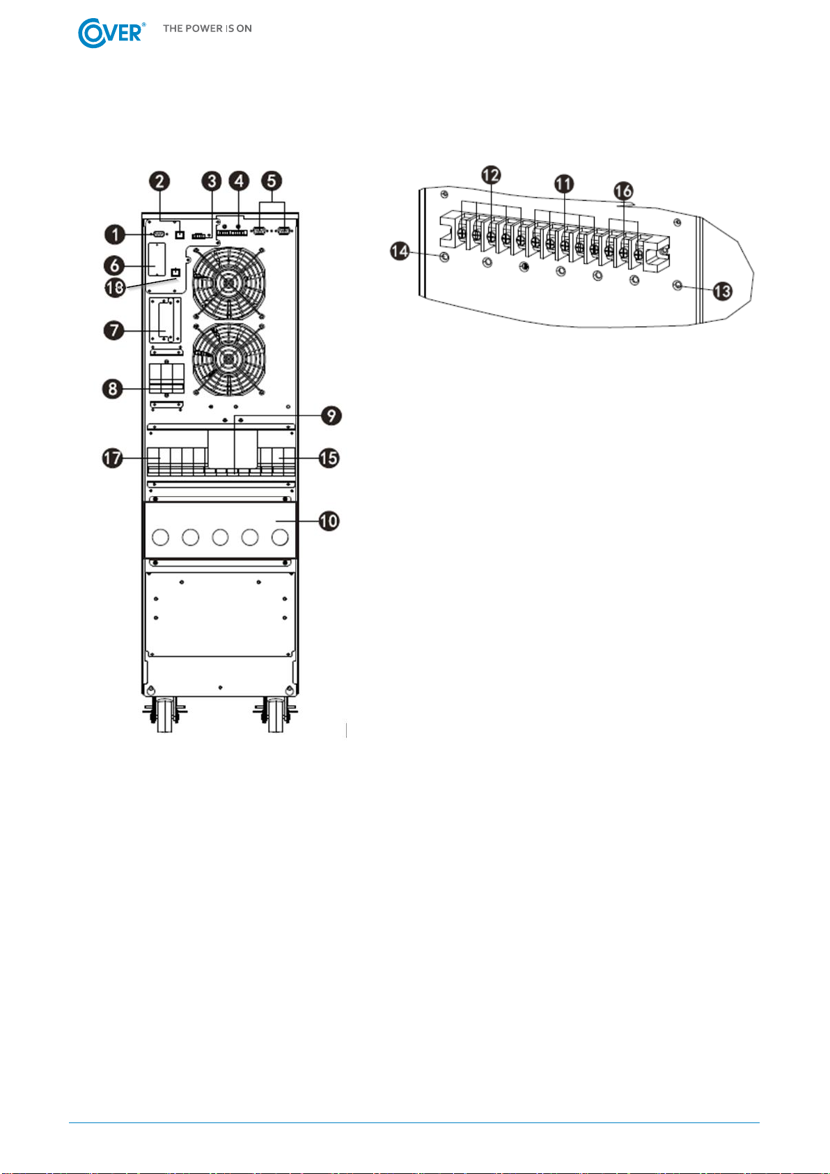
3. Appearance and connection............................................................................................................4
3.1. UPS rear panel..........................................................................................................................4
3.2. Connection of the remote REPO switch....................................................................................4
3.3. Connecting communication to the External Service Bypass EMBS. .........................................4
3.4. Connection of communication options.....................................................................................5
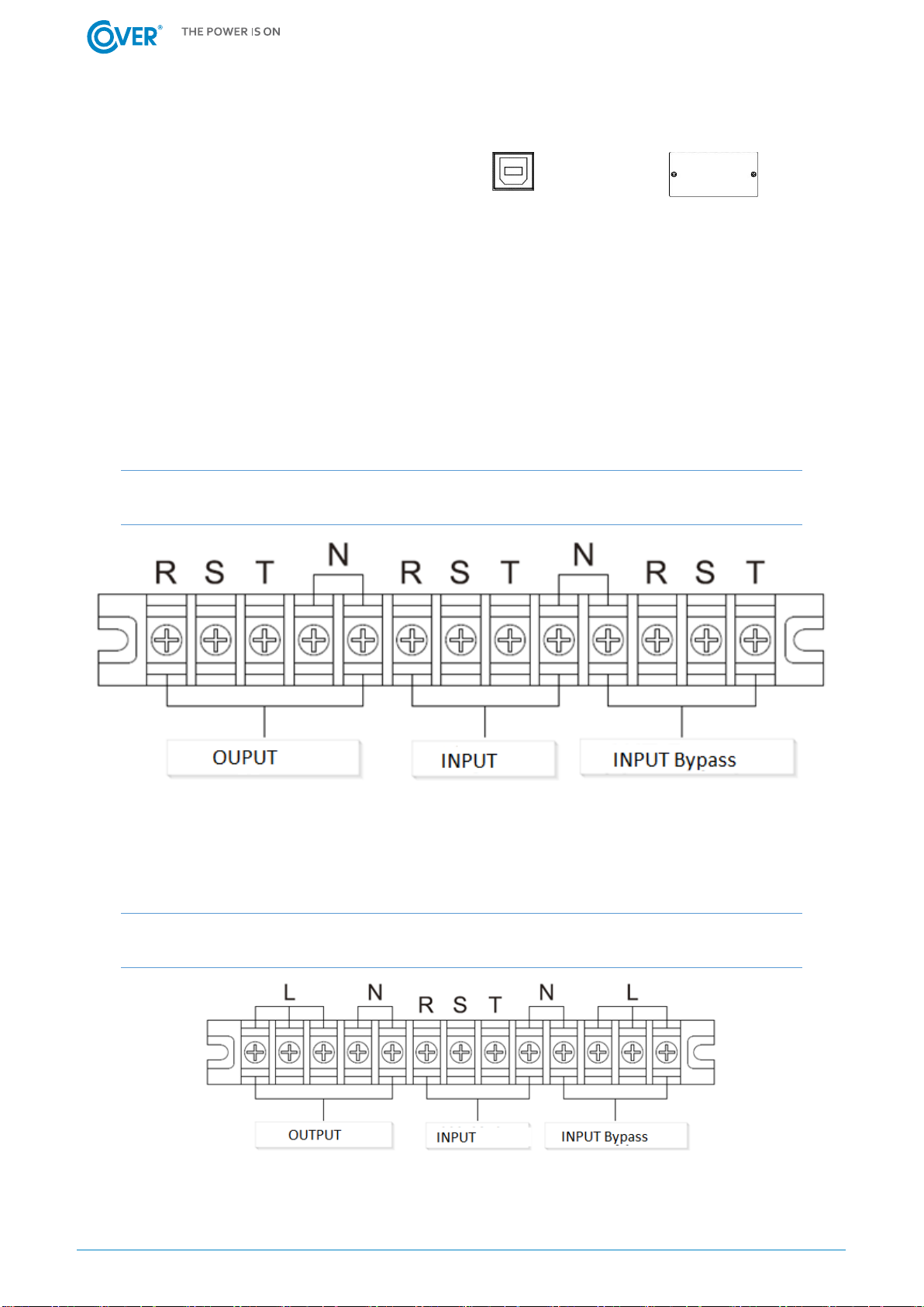
3.5. Power connection - configuration 3:3 ......................................................................................5
3.6. Power connection - configuration 3:1 ......................................................................................5
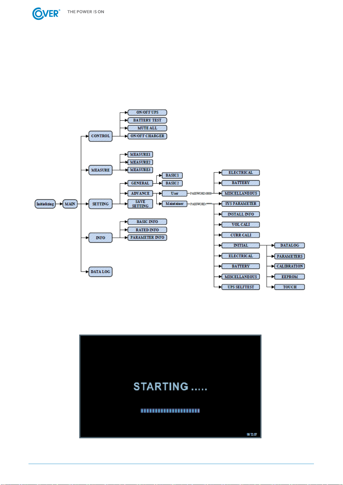
4. LCD display operation ......................................................................................................................6
4.1. Main display window ................................................................................................................6
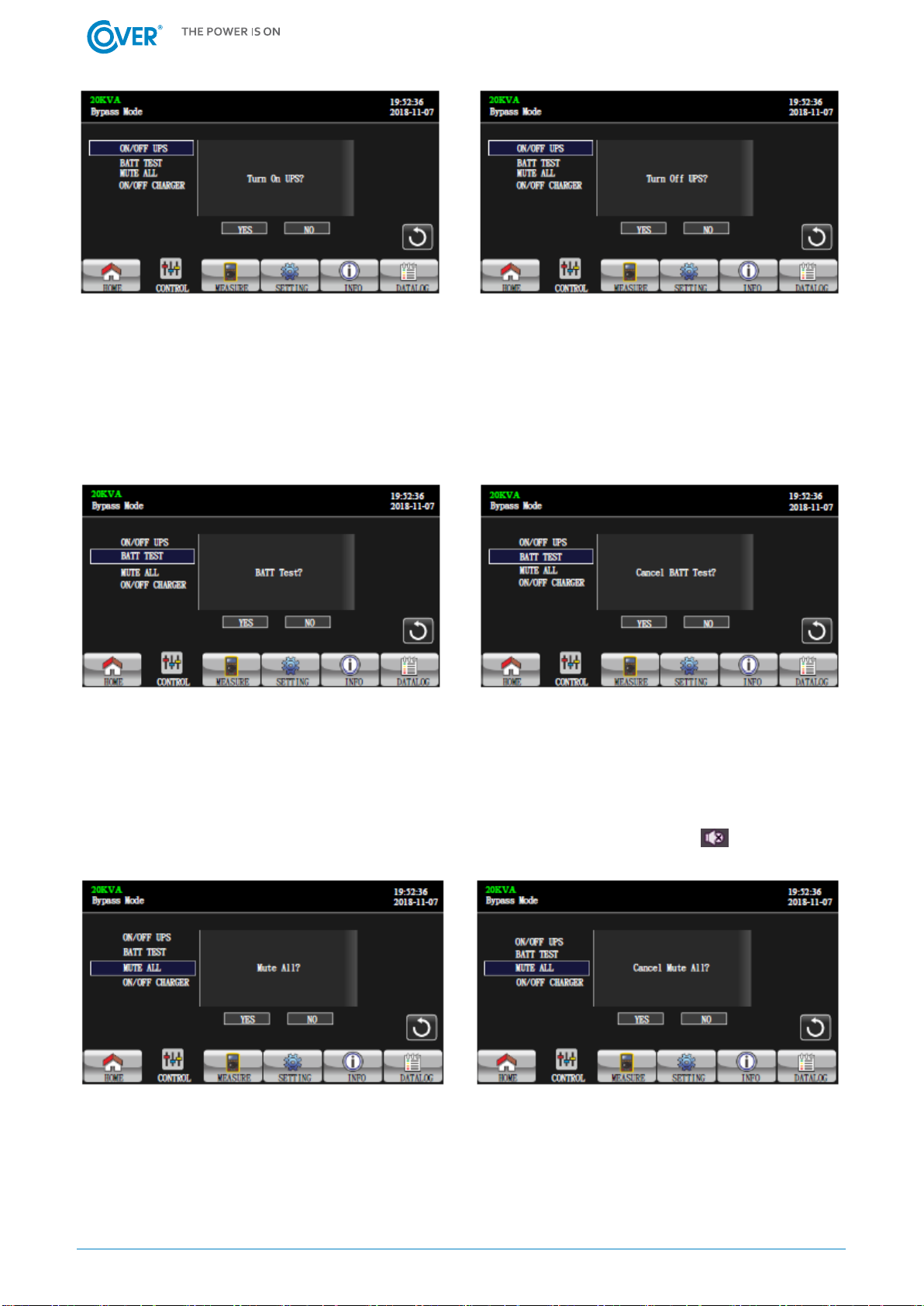
4.2. UPS control window..................................................................................................................7
4.3. Measure window.......................................................................................................................9
4.4. UPS configuration window (Setting) .......................................................................................11
4.5. Information window................................................................................................................13
4.6. Alarm window .........................................................................................................................13
5. Audible alarms and event codes....................................................................................................14
5.1. Audible alarms.........................................................................................................................14
5.2. Warning codes.........................................................................................................................14
6. UPS operations...............................................................................................................................15
6.1. Turn on the UPS from the mains.............................................................................................15
6.2. UPS shutdown .........................................................................................................................15
6.3. Turn on the UPS from the battery ..........................................................................................15
6.4. Switching UPS to the Maintenance Bypass mode ..................................................................16
6.5. Switching the UPS from Maintenance Bypass mode..............................................................16
6.6. Installing the software.............................................................................................................16
6.7. Working conditions .................................................................................................................16
6.8. The storage conditions............................................................................................................17
6.9. Battery change ........................................................................................................................17

1
1. Safety rules
This manual provides information on the safe use of the UPS. Before unpacking and installing the UPS,
read its contents and follow its instructions.
FULFILLED STANDARDS - EXECUTION
EN 62040-3
Uninterruptible Power Systems (UPS): Methods for determining
the properties and test requirements.
FULFILLED STANDARDS - ELECTROMAGNETIC COMPATIBILITY
EN 62040-2 :2006 C3
Guaranteed Power Systems (UPS): Electromagnetic Compatibility.
EN 61000-2-2 :2002
Electromagnetic Compatibility (EMC): Environment. Compatibility
levels for conducted low-frequency disorders and signaling in
public low-voltage power systems.
EN 61000-4-2 :2009
Electromagnetic Compatibility (EMC): Testing and measurement
methods - electrostatic discharge immunity test.
EN 61000-4-3 :2006
+A1 :2008 +A2 :2010
Electromagnetic Compatibility (EMC): Testing and measurement
methods - Radio frequency electromagnetic field immunity test.
EN 61000-4-4 :2004
+A1 :2010
Electromagnetic Compatibility (EMC): Testing and Measurement
Methods - Testing of immunity to a series of fast electrical
transients.
EN 61000-4-5 :2006
Electromagnetic Compatibility (EMC): Testing and Measurement
Methods - Surge Immunity Test.
EN 61000-4-6 :2009
Electromagnetic Compatibility (EMC): Test and Measurement
Methods - Immunity to conducted disturbances, induced by radio
frequency fields.
EN 61000-4-8 :2010
Electromagnetic Compatibility (EMC): Testing and measurement
methods - Testing of resistance to magnetic field at the frequency
of the power grid.
The device complies with the Directive 2004/108 / EC (EMC).
FULFILLED STANDARDS - SAFETY
EN 62040-1:2008
Uninterruptible Power Systems (UPS): General requirements and
requirements for UPS safety.
EN 60950-1:2006
Information technology devices. Security.
IEC 60417
Symbols used on devices
The device complies with the 2006/95 / EC (LVD) directive.
警告
危险
警告
危险
警告
危险

2
Keep these operating instructions! The manual contains important instructions on the use of the
UPS that should be followed during installation and use of the UPS device and batteries.
Condensation may occur if the power supply is cold and is brought into a warm place. Therefore,
you should wait at least 2 hours until it starts up.
To reduce the risk of electric shock, the UPS should be installed in a pollution-free room with
adequate temperature and humidity. The ambient temperature must not exceed 40 ° C.
Do not install the power supply in a place exposed to direct sunlight or other heat sources.
Do not connect devices that can overload the UPS output, e.g. laser printers, electric heaters, etc.
Cables should be connected and arranged in such a way that no one can accidentally step on or
disconnect them.
The UPS must be connected to a wall outlet with a working protective earth (GND).
Do not block the ventilation openings on the UPS. Make sure the vents are exposed and there is a
minimum of 25cm free space for ventilation.
The UPS power socket should be protected with an appropriate overcurrent switch.
The UPS has its own battery power source, so there may be voltage at the output sockets even
though the UPS is not connected to the mains.
Battery service should be performed by trained personnel who are knowledgeable about battery
operation and take appropriate precautions during its use.
If it is necessary to replace the battery, use batteries with the same number and parameters, i.e.
rated voltage, capacity and dimensions.
ATTENTION! Do not throw batteries into fire. The battery may explode.
ATTENTION! Do not open or mutilate the battery. Released electrolyte is harmful to the
skin and eyes. It can be toxic.
The battery can present a risk of electric shock. The following precautions should be taken when
working with batteries:
oRemove watches, wedding rings and other metal objects from your hand.
oUse tools with insulated handles.
oWear rubber gloves and boots.
oDo not lay tools or metal parts on top of the battery.
oDisconnect the battery charging source before connecting or disconnecting the battery
terminals.
Make sure the battery is not inadvertently grounded. If present, remove the source of ground fault.
Contact with any part of a grounded battery can result in electric shock.

3
2. Transport, unpacking the UPS
Check carefully that the carton and the contents are not damaged. If any damage is found,
immediately inform the shipping company and the power supply distributor.
Do not throw away the UPS packaging.
1. If no damage is found, carefully open the carton.
2. Unpack all protective elements (sponges, fillers).
3. Gently remove the UPS from the protective film and place it on a clean, flat and stable surface.
To prevent mechanical damage, shock and impact, only ship the UPS in its original
packaging.

4
3. Appearance and connection
3.1. UPS rear panel
1. RS 232 Port.
2. USB Port.
3. EPO port (fire protection switch connector).
4. Parallel port (optional).
5. Parallel port (optional).
6. Communication card slot (SNMP).
7. External battery socket.
8. Rectifier power disconnect switch for UPS.
9. Mechanical and service bypass.
10. Power cable connection strip.
11. Terminals for powering the UPS rectifier.
12. Terminals for connecting load power.
13. Ground terminal.
14. Ground terminal.
15. Internal bypass feeder disconnector of UPS.
16. Bypass power supply terminals.
17. Output disconnector.
18. Bypass communication connector ext. EMBS.
Fig. 1 UPS COVER JR 10 - 20K
3.2. Connection of the remote REPO switch
The UPS is equipped with an EPO port for connecting the Remote Emergency Power Off (REPO) switch.
The EPO port is configured as NC (normally closed), the activation of EPO occurs by breaking the
connection between Pin 1 and Pin 2 (removal of the jumper).
3.3. Connecting communication to the External Service Bypass EMBS.
The UPS is equipped with an EMBS connector, enabling communication to be connected to the
External Service Bypass, in order to enable the inverter to be turned off while operating on the External
Bypass. It is an NC (normally closed) port that is activated by breaking the connection between Pin 1
and Pin 2 (removing the jumper). Activating the port turns off the inverter and blocks the possibility
of its activation.

5
3.4. Connection of communication options.
The UPS has two communication ports:
USB
Intelligent Slot (SNMP)
To enable automatic management and monitoring of the UPS, connect the USB cable supplied with
the UPS, on one side to the USB socket on the UPS and on the other side to the USB socket on the
computer. The software provided with the UPS allows you to automate the processes of turning on /
off the receivers connected to the UPS depending on the events that occur on the UPS (e.g. power
failure, low battery level, overload, etc.). The software also allows for ongoing monitoring and logging
of UPS event history.
The UPS also has a slot for additional cards, which enables retrofitting with an SNMP network card for
remote communication via the network.
3.5. Power connection - configuration 3:3
NOTE: UPS operation configuration may only be changed by an authorized service!
Fig. 2 Terminal for connecting the power supply for COVER JR 10 - 20K configuration 3: 3 phase
3.6. Power connection - configuration 3:1
NOTE: UPS operation configuration may only be changed by an authorized service!
Fig. 3 Power supply terminal for COVER JR 10 - 20K configuration 3: 1 phase

6
4. LCD display operation
The PSU is equipped with a color LCD touch panel. Below is a diagram showing the possibilities and
the location of the various information available in the display menu.
For 3: 3 and 3: 1 UPS configurations there are differences in the number of displayed output phases
and bypass phases.
The screens below show a 3: 3 configuration. For a 3: 1 configuration, only 1 Output Phase and Bypass
are displayed.
4.1. Main display window

7
The main menu of the display shows the current operating mode of the UPS (energy flow through
individual functional blocks) and the parameters of power supply, batteries and UPS outputs.
To return to the main window from anywhere else, use the icon .
4.2. UPS control window
Control menu allows you to turn the UPS inverter on or off, run a battery test and silence the
audible alarm.
Select the UPS ON / OFF command to enable or disable the UPS inverter. The display will switch to the
following view asking you to confirm or cancel your selection.
Click "YES" to turn on / off the UPS. The display will return to the main window view.
Click "BACK" or "No" to return to the control window.
The display in the main window will show messages related to turning the UPS on (Turning on) or
turning off the UPS (Turning off).

8
Turn on UPS Turn off UPS
To start the battery test, select the "BATT TEST" command and confirm your selection with the "YES"
key.
To cancel the test, select the return to the "Back" menu or the "No" command.
The display in the main window will show messages related to Battery testing or Battery test failed.
Turn on battery test Turn off battery test
To silence the audible alarm, select the "MUTE ALL" command and confirm your selection with the
"YES" key.
To turn mute off, choose "Back" or with the command "No".
The mute icon appears on the display in the main window in the upper left corner .
Mute alarm Cancel mute alarm
The control menu also allows you to switch the battery charger on or off. Selecting the "ON / OFF
CHARGER" command enables it to turn on "Turn on Charger" if it is not working, or to turn it "Turn off
Charger" if it is currently active.

9
Turn on charger Turn off charger
4.3. Measure window
The screens below show a 3: 3 configuration. For a 3: 1 configuration, only 1 Output Phase and Bypass
are displayed.
In the measurements tab there are three windows between which you can switch with the
arrow keys up / down. The first window contains information about the parameters:
• Phase voltage of the L-N rectifier supply
• Phase-to-phase voltage of the L-L rectifier supply
• Rectifier supply frequency
• L-N inverter phase voltage
• L-L inverter phase-to-phase voltage
• Inverter frequency
• L-N phase voltage of the bypass supply
• Phase-to-phase voltage of the L-L bypass
• Bypass supply frequency
• Phase voltage at the UPS L-N output
• Phase-to-phase voltage at the UPS L-L output
• UPS output frequency

10
The following measurements are available in the second measurement window:
• Apparent power on the UPS
• Active power on the UPS
• Percentage of active power load of each output phase
• Percentage of apparent power load of each output phase
• Total percentage of active power load on the UPS
• Total UPS apparent power percentage
• Battery voltage +/-
• DC BUS +/- voltage
• Battery charging current
• Battery discharge current
• R / S / T temperatures
The third tab offers measurements of input and output currents, power factors, and measurements
of active and apparent input power as well as the load percentage.

11
4.4. UPS configuration window (Setting)
In the configuration tab there are two setting levels to choose from.
Basic mode (GENERAL) for the user allows setting
• Time
• Dates
• Language selection
• Power sources network / generator
• Service telephone number
• Contact person
• Service email address
• Mute alarms
Password authorization is required in the advanced mode available for the service.
Enter the password Password incorrect

12
In the service mode, it is possible to configure the electrical parameters:
Voltage, frequency
Working mode
Voltage tolerance ranges etc.
Battery parameters:
• Warning levels for high and low battery voltage
• Cut-off voltage
• Capacity and number of battery chains etc.
Other detailed settings are available exclusions for service technicians.
Other UPS parameters:
• Possibility to set the UPS to restart after the battery is discharged
• UPS shutdown delay
• UPS switch-on delay after power recovery
• Password change

13
4.5. Information window
In the information tab There is access to all configured parameters of the UPS, information
about the software version, serial number, etc. In the user mode, it is only possible to view the
parameters without the possibility of changing them.
4.6. Alarm window
In the alarms tab current existing alarms and warnings are shown. Sample battery disconnected
alarm below:

14
5. Audible alarms and event codes
5.1. Audible alarms
Description
Alarm
The possibility of mute
Bypass mode
1x / 2 minutes
YES
Battery mode
1x / 4 seconds
Damage
continuous
Overload
2x / 1 second
NO
Other
1x / 1 second
YES
5.2. Warning codes
Code
Error
Code
Error
01
Batteries not connected
36
Unbalanced inverter current
02
N wire missing
3A
Service Bypass included
04
Incorrect phase sequence of the rectifier
power supply
3C
Extremely unbalanced load
05
Incorrect phase sequence of the bypass
supply
3D
Unstable bypass
07
Battery overcharging
3E
Battery voltage too high
08
Low battery voltage
3F
Battery voltage unbalanced
09
Overload
40
Charger short circuit
0A
Fan failure
41
No Bypass power
0B
Active EPO
42
Isolation transformer overheating
0D
Overheating
43
DC BUS Soft Start Error
0E
Charger failure
44
EEPROM reset
21
Different rectifier feed lines in a parallel
system
45
External output switch open
22
Various bypass feed lines in a parallel
system
46
External battery switch open
33
Bypass mode lock after 3 times overload for
30 minutes
47
External Bypass switch closed
34
Inverter is out of symmetry
48
External input signal open

15
6. UPS operations
6.1. Turn on the UPS from the mains
1. Turn on the output disconnect switch on the rear panel of the UPS..
2. Turn on the battery disconnector located near the battery cabinet in the case of external batteries
to the ON position.
3. Turn on the bypass and UPS rectifier disconnectors. When power is applied, the LCD panel lights
up and the fans start to run. A few seconds later, the UPS enters Bypass mode.
Turning on the UPS power will turn on the Bypass mode. At this time, the receivers are
supplied with voltage from the UPS input and are not protected against power outages.
To start the UPS inverter, turn on the UPS - control menu.
4. In order to turn on the power supply, select the Control tab and the Turn on command.
5. A few seconds later, the UPS turns on the inverter and starts normal operation.
If the supply voltage is out of tolerance, the UPS starts to work from the battery. When
the battery is discharged, the power is turned off. The restoration of the power supply
automatically restarts the UPS to normal operation.
Attention! In order to obtain the maximum autonomy, charge the batteries at least 10 hours after the
first start. The maximum capacity of the battery is obtained after two complete discharge / charge
cycles.
6.2. UPS shutdown
1. Turn off the UPS inverter by selecting "OFF UPS" in the control window. The UPS will transfer to
Bypass mode.
In the event that the UPS is operating on battery, the above procedure turns off the UPS
and the voltage at the UPS output.
2. In Bypass mode, the output voltage is supplied directly from the mains. To completely shut down
the UPS, turn off the loads connected to the UPS and then disconnect the UPS power. Seconds
later, the UPS turns off the LCD panel and stops the fans.
3. Turn the battery circuit breaker to the OFF position.
4. Turn the output disconnect switch to the OFF position.
6.3. Turn on the UPS from the battery
1. Turn on the output disconnect switch on the rear panel of the UPS.
2. Turn on the battery disconnector located near the battery cabinet in the case of external batteries
to the ON position.
3. Press the “Power ON” button to turn the UPS into Stand-by mode. After the display is on, select
the "On" command in the control menu to turn on the inverter and apply voltage to the UPS
output.
4. A few seconds later, the UPS enters Battery mode.

16
6.4. Switching UPS to the Maintenance Bypass mode
The following procedure is for a UPS equipped with an external Maintenance Bypass.
Switching the UPS to the Maintenance Bypass mode means that the receivers are not
protected against power outages.
1. Turn off the UPS inverter (control tab). UPS will confirm shutdown with a single beep and switch
to Bypass mode.
2. Switch the external Maintenance Bypass from UPS position to BYPASS position.
3. To completely shut down the UPS, turn off the UPS power. Seconds later, the UPS turns off the
LCD panel and stops the fans.
4. Turn the battery circuit breaker to the OFF position.
6.5. Switching the UPS from Maintenance Bypass mode
1. Turn on the output disconnect switch on the rear panel of the UPS.
2. Turn on the battery disconnector located near the battery cabinet in the case of external batteries
to the ON position.
3. Switch on the UPS power in the UPS distribution board. When power is applied, the LCD panel
lights up and the fans start to run. A few seconds later, the UPS enters Bypass mode.
Make sure the Bypass LED is on to go to the next step.
4. Switch the external Maintenance Bypass from BYPASS position to UPS position.
5. In order to turn on the power supply (start the inverter), select the "Turn on" command in the
control tab.
6. A few seconds later, the UPS turns on the inverter and starts normal operation.
6.6. Installing the software
To take full advantage of the UPS, please install the provided ViewPower communication software.
During the installation, follow the instructions on the computer screen.
You must restart your computer after the installation process is complete. Restarting the computer
will automatically launch ViewPower, as shown by the ViewPower icon in the Windows system tray.
Środowisko pracy i eksploatacja UPS
6.7. Working conditions
To ensure the proper working conditions for the uninterruptible power supply system, the room with
the power supply must be clean, free of dust and dirt.
From time to time (at least every 6 months or more often depending on the degree of soiling), clean
the ventilation holes on the power supply to ensure free air flow.
To extend battery life, the ambient temperature should be between 15-25 ° C.

17
6.8. The storage conditions
If the UPS is not in use and storage or storage is envisaged, the batteries must be recharged periodically
to avoid damaging them. Depending on the storage temperature, the power supply should be
connected at least every 6 months to charge the battery. Typically, the batteries are charged within 4
hours to 90% of their capacity, while it is recommended to leave the power supply on for a period of
24-48 hours to fully charge the batteries, which will extend their life.
Temp. storage up to 20 ° C - charging every 6 months.
Temp. storage up to 30 ° C - charging every 3 months.
Temp. storage up to 40 ° C - charging every 1 month
6.9. Battery change
If the operating time of the UPS is halved with the batteries working properly, or the UPS reports a
battery alarm, the batteries should be replaced immediately.
After disconnecting the batteries, the receivers are not protected against power outages.
It is not recommended to replace the batteries while the UPS and receivers are operating.
It is not allowed to replace the batteries while the UPS is operating in battery mode!
This manual suits for next models
2
Table of contents
Other Cover UPS manuals
Popular UPS manuals by other brands

Steren
Steren MOV-015 instruction manual

Online USV
Online USV ONLINE XANTO S Series user manual

Atlantis
Atlantis Linepower X1 user manual

Voltronic Power
Voltronic Power 1K Online UPS For Dual-mains Input user manual

Vertiv
Vertiv Liebert NXL Series Operation and maintenance manual

Best Power
Best Power Fortress 750 VA user guide

Integra
Integra OPTIMA T10 1.5K user manual

Orion Power Systems
Orion Power Systems Edge Pro Series user manual

Powerex
Powerex OL 1K RM user manual

Eaton
Eaton Powerware 9390 Installation and operation manual

SynQor
SynQor 3-Phase UPS-1500 Series Operator's guide

Tripp Lite
Tripp Lite SMARTINT3000VS owner's manual