Cover NHS Series User manual

UPS
C
C
CO
O
OV
V
VE
E
ER
R
R
N
N
NH
H
HS
S
S
S
S
Se
e
er
r
ri
i
ie
e
es
s
s
True On-Line Double Conversion
30-120 kVA
User Manual
V.1730-1

The content of this manual is copyrighted by the publisher and can
not be reproduced without prior permission. We reserve the right to
modify the design and specifications without prior notice.
© Copyright 2016
COMEX S.A.
All rights reserved.

Table of Contents
1. Precautions ......................................................................................................................................... 1
2. Installation procedure.......................................................................................................................... 5
2.1. Introduction................................................................................................................................. 5
2.2. Initial check................................................................................................................................. 5
2.3. Location...................................................................................................................................... 5
2.3.1. UPS room........................................................................................................................... 5
2.3.2. Battery room....................................................................................................................... 6
2.3.3. Storage ............................................................................................................................... 6
2.4. Unpacking, checking and setting................................................................................................ 6
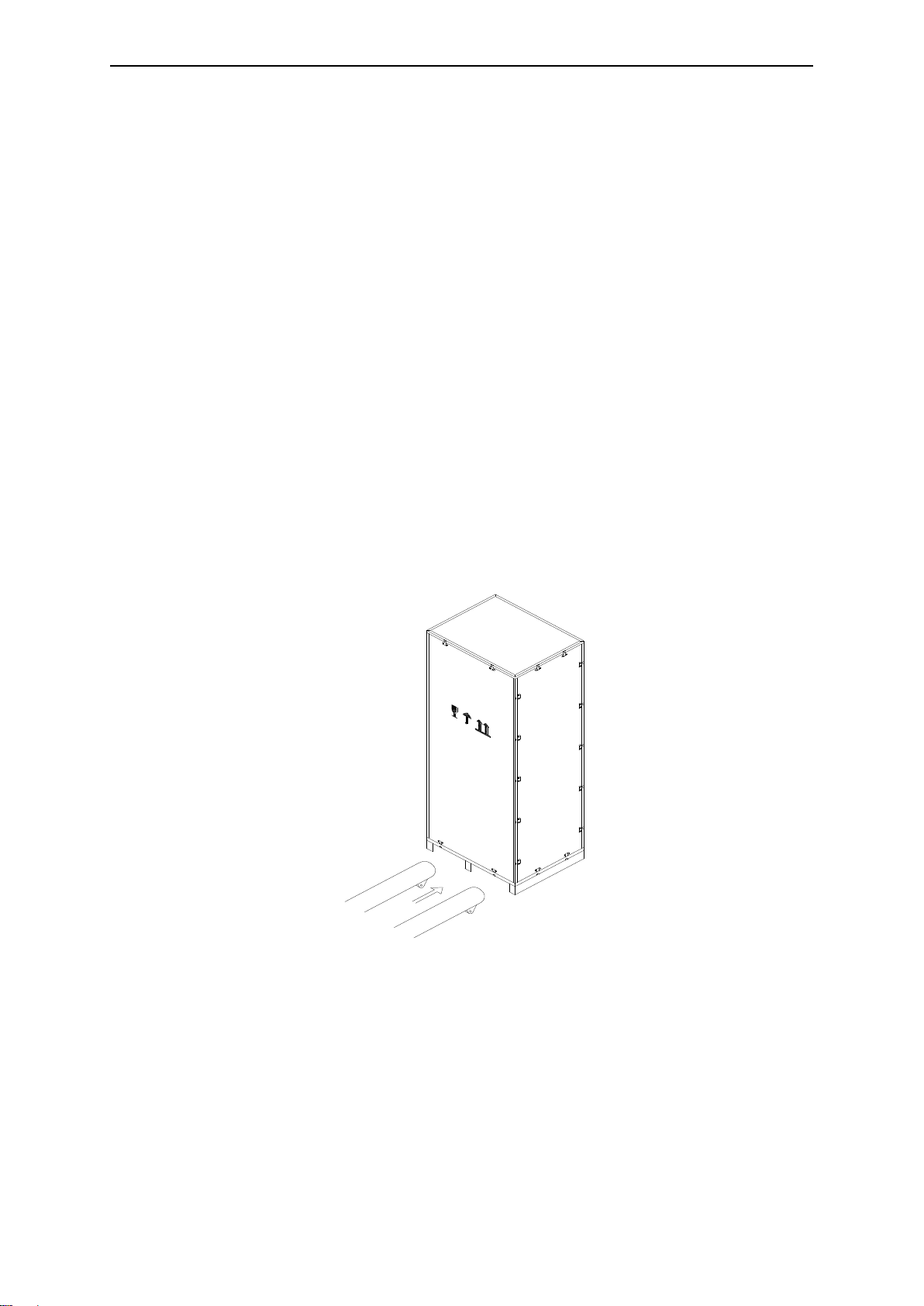
2.4.1. Unpacking........................................................................................................................... 6
2.4.2. UPS components................................................................................................................ 8
2.4.3. Service space..................................................................................................................... 8
2.5. Safety elements.......................................................................................................................... 8
2.5.1. UPS input power supply ..................................................................................................... 9
2.5.2. Battery circuit protection..................................................................................................... 9
2.6. Power cords.............................................................................................................................. 10
2.6.1. Maximum currents of the power supply............................................................................ 10
2.6.2. Connecting wires.............................................................................................................. 11
2.7. Communication cables ............................................................................................................. 11
2.7.1. Dry Contact - sensor for detection of battery and environmental temperature ................ 12
2.7.2. REPO switch port ............................................................................................................. 12
2.7.3. Genset interface ............................................................................................................... 13
2.7.4. Output signal - bypass operation and indication of external bypass switch position. ...... 13
2.7.5. Output signal - Battery low ............................................................................................... 14
2.7.6. Output signal - event warning........................................................................................... 15
2.7.7. Output signal - no power supply, battery operation.......................................................... 15
2.7.8. Port USB, RS-232 and RS-485 ........................................................................................ 16
2.7.9. Smart Slot x2 .................................................................................................................... 16
2.8. Installation drawings................................................................................................................. 17
3. UPS operation modes....................................................................................................................... 19
3.1. Introduction............................................................................................................................... 19
3.2. Principle of operation................................................................................................................ 19
3.2.1. Bypass module................................................................................................................. 19
3.3. Power supply operation modes................................................................................................ 20
3.3.1. Normal operation.............................................................................................................. 20
3.3.2. Battery operation .............................................................................................................. 20
3.3.3. The restart mode of the power supply after power back.................................................. 20
3.3.4. Bypass mode.................................................................................................................... 20
3.3.5. Service bypass mode ....................................................................................................... 21
3.3.6. Eco mode.......................................................................................................................... 21
3.3.7. Frequency converter mode............................................................................................... 21
3.3.8. Parallel operation mode.................................................................................................... 21
3.3.9. Hiberation mode ............................................................................................................... 21
3.4. Battery management ................................................................................................................ 21
3.4.1. Basic functions.................................................................................................................. 21
3.4.2. Advanced functions (automatic tests and service)........................................................... 22
3.5. Battery protection ..................................................................................................................... 22
4. User's manual for the power supply.................................................................................................. 23
4.1. Power connectors..................................................................................................................... 23
4.2. Procedures for starting the power supply................................................................................. 24
4.2.1. Running the power supply or UPS units running parallel to the UPS from the state of total
shutdown 24
4.2.2. Starting the UPS from the battery (“cold start”) ................................................................ 25
4.3. Procedures for switching the power supply between operating modes................................... 25
4.3.1. Switching from normal operation to battery operation...................................................... 25
4.3.2. Switching from normal operation to Bypass operation..................................................... 26
4.3.3. Switching from Bypass mode to normal operation........................................................... 26
4.3.4. Switching from normal operation to service Bypass mode. ............................................. 26
4.3.5. Switching from service Bypass mode to normal operation .............................................. 26
4.3.6. Adding/Removing Hot-swap power modules ................................................................... 27
4.4. The procedure of completely turning off the power supply ...................................................... 27

4.5. Emergency shutdown using EPO............................................................................................. 27
5. LCD panel operation ......................................................................................................................... 28
5.1. Introduction............................................................................................................................... 28
5.1.1. LED indicators .................................................................................................................. 29
5.1.2. Audible alarm.................................................................................................................... 29
5.1.3. Function keys.................................................................................................................... 30
5.2. LCD touch display .................................................................................................................... 30
5.2.1. Main menu........................................................................................................................ 31
5.2.1.1 Cabinet ............................................................................................................................. 31
5.2.1.2 Hot-swap module.............................................................................................................. 33
5.2.1.3 Settings............................................................................................................................. 31
5.2.1.4 Log.................................................................................................................................... 31
5.2.1.5 Operate............................................................................................................................. 39
5.2.1.6 Scope................................................................................................................................ 40

COVER serii NHS –Instrukcja Obsługi
COMEX S.A.
1
1. Precautions
This user's guide contains the necessary information on the installation and use of the COVER NHS
modular power supplies.
Before installing and using, please read the manual carefully.
The UPS must be installed and configured by an authorized service center of the manufacturer or
distributor. In the case of installations by persons without the required experience, there is a risk of users
being exposed to health or life. Persons not entitled to the installation may damage the power supply,
which in this case is not subject to the terms of the warranty.
This user's guide contains the necessary information on the installation and use of the NHS COVER
power supplies.
警告
危险
FULFILLED STANDARDS - EXECUTION
EN 62040-3
Uninterruptible power systems (UPS): Methods for determining
properties and test requirements.
警告
危险
COMPLETED STANDARDS - ELECTROMAGNETIC COMPATIBILITY
EN 62040-2 :2006 C3
Uninterruptible Power Supply (UPS): Electromagnetic compatibility.
EN 61000-2-2 :2002
Electromagnetic compatibility (EMC): Environment. Compatibility levels
for disorders conducted by m.cz. and signaling in public low voltage
power systems.
EN 61000-4-2 :2009
Electromagnetic compatibility (EMC): Test and measurement methods -
electrostatic discharge resistance test.
EN 61000-4-3 :2006
+A1 :2008 +A2 :2010
Electromagnetic compatibility (EMC): Test and measurement methods -
Immunity test for radio frequency electromagnetic fields.
EN 61000-4-4 :2004
+A1 :2010
Electromagnetic compatibility (EMC): Test and measurement methods -
Test of resistance to a series of fast electrical transient states.
EN 61000-4-5 :2006
Electromagnetic compatibility (EMC): Test and measurement methods -
Impact resistance test.
EN 61000-4-6 :2009
Electromagnetic compatibility (EMC): Test and measurement methods -
Resistance to conductive disturbances induced by radio frequency
fields.
EN 61000-4-8 :2010
Electromagnetic compatibility (EMC): Test and measurement methods -
Test of resistance to magnetic field at the frequency of the power
network.
EN 61000-4-11 :2004
Electromagnetic compatibility (EMC): Test and measurement methods -
Immunity tests for voltage dips, short interruptions and voltage
changes.
The device complies with the directives 2004/108 / EC (EMC).
警告
危险
COMPLETED STANDARDS - SAFETY
EN 62040-1 :2008
Uninterruptible Power Systems (UPS): General requirements and UPS
safety requirements.
EN 60950-1:2006
Information technology devices. Safety.
IEC 60417
Symbols used on devices
The device complies with the Directive 2006/95 / EC (LVD).

COVER serii NHS –User Manual
COMEX S.A.
2
警告
危险
NOTE - Large leakage current
The connection of the protective conductor (PE) is essential and must be made before connecting
the remaining working conductors (power supply, consumer, battery).
Grounding should be carried out in accordance with prevailing standards and practical knowledge
applicable at the place of installation.
The leakage current exceeds 3.5 mA and is less than 1000 mA.
When choosing immediate-action RCCB or RCD devices, the transient and fixed leakage currents
that may occur during commissioning must be taken into account.
Select residual current circuit breakers (RCCB) that are sensitive to unidirectional DC current pulses
(Class A) and insensitive to transient current pulses.
It should also be remembered that a given RCCB or RCD device conducts the leakage currents of
the receiver.
警告
危险
Operation
There is dangerous voltage in the uninterruptible power supply housing. The risk of contact with such
a voltage is kept to a minimum, as live components are behind a closed housing. Additional internal
protective covers make the device protected in accordance with protection class IP20.
Normal operation of the device, taking into account the recommended operating procedures, poses
no threat to personnel.
All maintenance and service procedures require access to the interior of the device and should only
be carried out by trained employees.
警告
危险
High battery voltage> 400 Vdc
All work related to the operation and installation of batteries can be performed by a properly trained
service.
After connecting the battery, the voltage at their terminals exceeds 400 Vdc and is potentially lethal.
Battery manufacturers give detailed precautions that must be followed when working on or around
battery-powered large batteries. Such measures should always be strictly observed.
Particular attention should be paid to recommendations regarding local environmental conditions and
the provision of protective clothing, first aid and fire-fighting equipment.
警告
危险
Work in service bypass mode
The PSU is equipped with an internal service bypass. After using it, the input and output terminals of
the UPS can still be energized, even though the UPS is turned off.
警告
危险
Observing the operating conditions
Damage to the UPS resulting from a faulty connection to the electrical system, or failure to observe
the conditions of failure-free operation of the equipment mentioned in the operating instructions will
be treated as a violation of the terms of the warranty.
警告
危险
UPS power system
The power supply unit is suitable for installation in 3-phase, 5-wire installations with a grounded
neutral conductor.

COVER serii NHS –User Manual
COMEX S.A.
3
To ensure safe and trouble-free operation of the UPS, you should:
Check the contents of the package; in the case of any damage found, inform the supplier
immediately.
Do not discard the original packaging; if it is necessary to send the power supply back to the service
point, the packaging will protect the device against mechanical damage; damage caused during
transport is not covered by the warranty.
Do not dispose of the warranty card supplied with the adapter, which is the basis for applying for a
free repair during the warranty period.
Keep this manual as it contains the necessary information on the use and operation of the power
supply; when uncertainty arises, as to the way it is used, it will be the source of important
information.
There are no control elements inside the UPS intended for user operation.
Do not disassemble the housing or disassemble the UPS in any other way.
Do not remove the guarantee seals.
The electrical installation that works with the UPS should comply with the current regulations and
standards in force in the Republic of Poland.
Do not use the UPS in water or excessive humidity conditions.
Do not use the UPS in rooms where flammable gases, corrosive substances are available.
Protect the UPS against liquids and other substances and objects, pay special attention to the
cleanliness of the room; The dust conducts electricity and is a frequent cause of damage to
electronic components.
Operate the device in an air-conditioned room; do not cover the ventilation openings in the UPS
housing and the fan outlets at the rear.
Immediately switch the device off if liquid or a white, powdery substance escapes from the housing.
Do not dispose of used batteries as they contain hazardous metals and other substances harmful to
the environment.
To protect against electric shock, install the UPS in a closed room, free from conductive substances;
the room temperature can not exceed 40 ° C.
All work related to the repair or installation of the device should be performed by a suitably qualified
and trained distributor service.
The recommended temperature of the room in which the batteries are located should be 15-25ºC.
When connecting the power supply for maximum protection against electric shock, connect the
protective conductor first.
Do not lift or otherwise move the battery module and UPS after connecting.
Do not connect or disconnect data lines during atmospheric discharges.
In an indoor environment, the product may cause wave interference radio, which requires setting the
power supply at a suitable distance from devices sensitive to interference.
Only use 3-pole circuit breakers on UPS power supply. Disconnecting the neutral in the UPS supply
path may damage it.
Do not perform any electrical work interfering with the electrical system before and after the UPS,
while the UPS system is operating. Damages resulting from this title (eg change of phase sequence)
are not covered by the guarantee.
The UPS in accordance with the requirements of standard 62040 is a low-emission product in class
C3. Nevertheless, in the user's environment, the UPS may cause radio interference. In this case, the
user is required to take additional actions to eliminate interference to other equipment by, for
example, changing the setting of the power supply.
In the event of a malfunction of the power supply or with visible signs of damage to the UPS,
batteries or wires, contact an authorized distributor.

COVER serii NHS –User Manual
COMEX S.A.
4
To ensure safe and trouble-free operation of the battery:
Keep the room temperature within the permitted range. The battery life drastically shortens as
the temperature rises, which limits the autonomy of the power supply during battery operation.
Batteries stored in the state not connected to the charger are self-discharging. It is
recommended to charge the battery periodically at least:
oTemp. storage up to 20 ° C - charging every 6 months.
oTemp. storage up to 20 ° C - charging every 3 months.
oTemp. storage up to 20 ° C - charging every 1 month.
Battery maintenance should be carried out by properly trained personnel.
There is always voltage on the battery terminals. Even a discharged battery can create a high
short circuit current which, in addition to damage to the batteries and leads, can cause burns to
the user.
The voltage of one battery is not dangerous. However, many batteries connected in series
produce dangerous voltage.
When replacing the batteries, always replace all batteries with new ones of identical parameters,
quantity and age.
Batteries are a source of energy and can generate very high currents. To avoid shock or short-
circuit between the poles of the battery, use the following tips during operation:
oRemove your watch, finger rings and other metal parts that could lead to a short circuit.
oUse tools with insulated handles.
oWear rubber boots and gloves.
Under no circumstances should you place any metal tools or other metal parts on the batteries.
Do not dispose of batteries in a fire, which may cause explosion and life exposures.
Do not damage the battery and open it. There are dangerous substances inside that can cause
burns. In case of contact with the electrolyte, rinse the area with plenty of water and consult a
physician if necessary.
New batteries often do not provide full performance after pre-charging. It may be necessary to
perform several full discharging / charging cycles before achieving optimal performance.
Dispose of batteries in accordance with applicable regulations for toxic and harmful waste.

COVER serii NHS –User Manual
COMEX S.A.
5
2. Installation procedure
This chapter is devoted to the method of installation, method of laying and wiring of the UPS.
2.1. Introduction
The chapter presents the basic requirements for the location and wiring of the power supply. The
description presents a step by step installation instruction, which is a series of guidelines for the service
to be followed during assembly.
警告
危险
Warning - Installation may only be carried out by an authorized service center
1. Do not connect electrical devices to the power supply before finding a service technician that the
power supply is properly connected and configured.
2. The UPS should be installed by qualified technical personnel in accordance with the guidelines
contained in this chapter.
警告
危险
Warning: dangerous batteries
Special precautions must be observed when working with batteries connected to the power supply.
After connecting the battery, the voltage on the terminals exceeds 400Vdc and is potentially fatal.
To protect your eyes against accidental arcing, it is recommended to use safety goggles.
Additionally, it is recommended to:
Remove rings, watches and all metal objects.
Use only tools with insulated handles.
Wear rubber gloves.
If the battery leaks or the battery is damaged in any other way, it must be replaced. Damaged
batteries should be stored in a container resistant to sulfuric acid and disposed of in accordance
with local regulations.
If the electrolyte comes into contact with the skin, immediately contaminate the area with water.
2.2. Initial check
Perform the following checks before installing:
Check visually that the supplied devices, i.e. the UPS and batteries, have not been damaged as a
result of their transport. Damages should be reported immediately to the supplier.
Verify compliance of the delivered equipment with the installation requirements. The power of the
PSU is described on the label each time.
2.3. Location
2.3.1. UPS room
Zasilacz UPS jest przeznaczony do instalacji wewnątrz budynku. Urządzenie powinno znajdować się w
czystym środowisku o odpowiedniej wentylacji, aby utrzymać temperaturę otoczenia w wymaganym
specyfikacją zakresie. UPS zapewnia wymuszone chłodzenie konwekcyjne przez wewnętrzne
wentylatory. Zimne powietrze dostaje się do urządzenia poprzez otwory wentylacyjne umieszczone w
przedniej części obudowy i wydmuchiwane jest przez grille znajdujące się w tylnej części obudowy. Nie
należy blokować otworów wentylacyjnych.
Uwaga: UPS powinien być zainstalowany na stabilnym i niepalnym podłożu.

COVER serii NHS –User Manual
COMEX S.A.
6
2.3.2. Battery room
Battery temperature should be stable, because it is the main parameter affecting the battery life and
capacity. The optimal battery temperature is 15-25 ° C. It is recommended to maintain a nominal
temperature of 20 ° C.
Working at a higher temperature shortens the battery life, and at a lower temperature it reduces the
battery capacity. Any increase in battery operating temperature by a further 8 ° C, reduces the service
life by 50%.
Keep batteries away from heat sources and hot air outlets.
When installing the battery outside the UPS, use the battery circuit protector located as close as
possible to the battery. The cables connecting the batteries and the UPS should be as short as possible.
2.3.3. Storage
If the device is not installed and requires storage, protect it from excessive moisture and high
temperatures. The batteries should be stored in a dry and cool room with good ventilation. The most
suitable storage temperature for batteries is 20-25 ° C.
2.4. Unpacking, checking and setting
Before unpacking, carefully inspect the delivered device for damage during transport. After removing
from the packaging, check again if the equipment does not show signs of damage. If any damage
occurs, please report it to the supplier immediately.
2.4.1. Unpacking
The power supply is supplied in a wooden case. The method of opening the housing is shown below.
Figure 2-1 The way of opening
First, open the upper housing cover, then dismantle the side walls of the housing. Be careful not to
scratch the power supply casing. See Figure 2-2.

COVER serii NHS –User Manual
COMEX S.A.
7
Figure 2-2 Disassembly of the housing
Side protection should be removed. Unpacked UPS looks like the picture below.
Figure 2-3 View of the power supply after disassembly of the housing
Note: Remove the screw that connects the UPS enclosure to the wooden pallet, and then place the
power supply at the point of installation. Disassembly should be carried out carefully so as not to scratch
the housing.
Check the correctness of the delivered equipment on the label located on the back of the UPS door. The
label contains basic information about the model, power, etc.
Note: Dispose of materials after disassembly in accordance with local environmental protection
requirements.

COVER serii NHS –User Manual
COMEX S.A.
8
In order to extend the service life of the device, it is necessary to provide a suitable place for its
installation, which should guarantee:
Easy connection to the installation
Sufficient space for service
Ventilation for proper cooling of the power supply
Protection against gases that can cause corrosion
Protection against excessive moisture and heat sources
Protection against dust and other impurities
Suitable fire protection
The working temperature should be in the range of 20-25ºC. At this temperature, the batteries
exhibit optimum performance.
2.4.2. UPS components
The components of the UPS are shown in the figures below:
Figure 2-4 View of the NHS 120 UPS (front and rear)
2.4.3. Service space
There are no ventilation openings on the side walls of the power supply, therefore no space is required
from the side. However, for access to the device from each side, it is recommended to keep min. 50 cm
of service space.
It is required to provide adequate space from the front of the power supply to fully open the door and the
possibility of disassembling the power modules and free drawing of cold air from the environment.
Recommended space from the front 100cm.
Due to the required free air blow and circulation, the space required from the back of the power supply is
80cm.
2.5. Safety elements
For safety reasons, it is necessary to install appropriate protections in the form of over-current circuit
breakers or other protective devices in the UPS power distribution board. This chapter provides general
practical information for the installation needs of qualified electricians. In addition, personnel with
appropriate knowledge and qualifications should have knowledge about standards and standards in

COVER serii NHS –User Manual
COMEX S.A.
9
force on the local market regarding the type and cross-sections of cables, their arrangement and
loadability. It is recommended to use flexible LgY or OpD type hoses.
2.5.1. UPS input power supply
The UPS should be supplied from an electrical switchgear equipped with a suitable security device
selected for the maximum system power, and flexible hoses with appropriate current carrying capacity
matched to the protection used.
If it is required to install RCDs on the UPS, please note that these devices should:
be sensitive to unidirectional DC current pulses (class A)
not be sensitive to transient current pulses
have adjustable sensitivity in the range of 0.3 - 1.0 A.
The RCD must be sensitive to unidirectional DC current pulses, and insensitive to transient current
pulses, as shown in the figure below:
Figure 2-5 Marking the RCD
2.5.2. Battery circuit protection
The battery required for correct operation of the power supply consists of 36 - 44 12V batteries
connected in series. A 3-wire installation with a center neutral point, taken from the central connection
between the 20 and 21 batteries (for 40 items) is required. The battery circuit must be protected by an
appropriate fuse, selected according to the UPS capacity and the number of batteries.
A detailed drawing of the battery installation is shown below:
Figure 2-6 Diagram of connecting in series 40 pcs of battery with a central neutral point

COVER serii NHS –User Manual
COMEX S.A.
10
2.6. Power cords
The main factors that affect the selection of wires are voltage, current, and room temperature and cable
installation conditions.
The system power cords must be selected in accordance with applicable regulations at the place of
installation and be consistent with the following description:
The input power supply cables must be matched to the maximum input current and the maximum
battery charging current indicated in the table below, taking into account the power rating of the power
supply and the AC input voltage.
The output and bypass cables must be matched to the rated output current given in the table, taking into
account the power rating of the power supply and the AC output voltage.
Battery cables must be matched to the battery discharge current at voltage at the end
discharging, given in the table taking into account the power rating of the PSU.
警告
危险
Warning
BEFORE PERFORMING THE WIRING OF THE POWER SUPPLY, MAKE SURE THAT THE
POSITION AND FUNCTION OF EXTERNAL DISTRIBUTES WILL COMBINE THE INPUT /
OUTPUT POWER SUPPLY WITH A POWER DISTRIBUTION PANEL.
CHECK THAT THE FOREGOING POWER SOURCES ARE ELECTRICALLY DISCONNECTED
AND SIZE THE NECESSARY WARNINGS TO PREVENT THESE FAILURE TO INCLUDE THAT
THAT THE VOLTAGE DOES NOT APPEAR ON CABLES WITH A UPS POWER SUPPLY.
2.6.1. Maximum currents of the power supply
The table below shows the maximum currents for each UPS system power. The given currents are used
to select the appropriate protections in the power, battery and receiver lines as well as the appropriate
cable cross-sections. Currents given at 230 / 400Vac installation.
Table 2-1 Power supply table
System
NHS 120
Power
120 kVA
Dimensions
600x655x1600
Supply
Nominal
current A
202
Output
Nominal
current A
180
Batteries
Nominal
current A
284

COVER serii NHS –User Manual
COMEX S.A.
11
2.6.2. Connecting wires
警告
危险
Warning
The operations described in this chapter should be performed by a properly trained team of service
technicians. The contracting authority is responsible for preparing the power supply and receiving
installation for the power supply.
After properly setting and securing the power supply before moving it, connect the wires with the
following rules:
1. Check that the power supply is completely disconnected from the external power source and that
the service switch on the power supply is open. Ensure that these power sources are electrically
isolated and arrange the necessary warning signs to prevent them from being accidentally switched
on.
2. Connect the protective ground wire. The neutral connection must comply with local regulations and
applicable standards.
3. With single-circuit connection (common rectifier and bypass input) connect the power supply cables
to the input (Main Input A-B-C-N), output leads to the output terminals (Output A-B-C-N). Tighten the
M8 bolts, with a force of 13 Nm, M10 with a force of 18 Nm. Check the correct order (rotation) of the
phases.
4. Connect the power cords between the UPS and the battery disconnector. Check the correct polarity.
警告
危险
Warning - Hazardous voltage at the battery terminals
Make sure that the polarity of the battery is correctly connected. Positive terminal of battery to
positive terminal (BAT +) on UPS, negative terminal of battery to negative terminal (BAT-) on UPS,
neutral terminal of battery to neutral terminal (N) on UPS.
5. Install the protective cover and rear cover of the power supply.
2.7. Communication cables
As you can see in the drawing below, the communication interface of the power supply located on the
Bypass module consists of the contact interface (Dry Contact J2-J10), RS-232, RS-485 communication
interface and SNMP card slot as well as the LBS synchronization port.
USB 485
232
Parallel Interface
Dry Contact Battery Cold Start
SNMP
Intelligent Slot
Figure 2-7 Communication interface of the 120 KVA power supply
The cables connected to the DryContact interface must be unprotected and separated from the AC
working conductors. In addition, the wires should be double insulated with a cross-section of 0.5 - 1.5
mm2, and their maximum length should not exceed 50m.

COVER serii NHS –User Manual
COMEX S.A.
12
2.7.1. Dry Contact - sensor for detection of battery and environmental
temperature
Dry Contact J2 and J3 input signals are used to detect the temperature of the battery and the
environment at the sensor's installation location. The battery temperature sensor is used to compensate
for the temperature of the battery charging voltage. The interface design and description of connections
are shown below.
J2 J3
TEMP_BAT
TEMP_ENV
Figure 2-8 View of the DryContact J2 and J3 interface
Table 2-2 Description of DryContact J2 and J3 interface pins
Pin
Description
Purpose
J2.1
TEMP_BAT
Battery temperature detection
J2.2
GND
Ground
J3.1
TEMP_ENV
Enviroment temperature detection
J3.2
GND
Ground
Note: Use appropriate temperature sensors for proper detection (R25 = 5 Ohm, B25 / 50 = 3275), please confirm the
compatibility of parameters at the supplier at the time of ordering.
2.7.2. REPO switch port
The UPS is equipped with a REPO interface enabling remote switching off of the UPS in an emergency
situation (eg fire). The function can be activated by pressing a key on the front panel of the power supply
or remotely using the remote switch REPO.
J4 connector is used to connect the remote REPO switch. During normal operation, shorting of the NC
pin and + 24V is required. Activation of the EPO signal occurs when the NC and + 24V signal is opened
or by shorting the NO and + 24V pins. The interface design and description of connections are shown
below.
J4
EPO_NC
+24V
EPO_NO
+24V
EPO_NC
+24V
+24V
J4
EPO_NO
+24V
+24V
+24V
Figure 2-9 Interface REPO

COVER serii NHS –User Manual
COMEX S.A.
13
Table 2-3 Description of the REPO interface pins
Pin
Description
Purpose
J4.1
EPO_NC
EPO is activated when disconnected from J4.2
J4.2
+24V
+ 24V, voltage for connection to NC and NO
J4.3
EPO_NO
EPO is activated when connected to J4.2
Use external potential-free REPO circuit breakers using a normally closed (NC) or normally open (NO)
contact.
If you do not use the remote REPO switch, the J4.1 pin must be connected to J4.2 and the J4.2 pin
disconnected from J4.3.
警告
危险
Warning
1. Using the EPO switch stops the operation of the rectifier, inverter and Bypass, and disconnects
the voltage at output.
2. As standard, pins J4.1 and J4.2 are connected to each other when the equipment is delivered.
2.7.3. Genset interface
The J5 input connector is used to signal the connected generator. The connection of J5.2 pins with J5.1
(+ 24V) indicates that the system is operating from a power generator. The interface design and
description of connections are shown below.
J5
GEN
+24V
AUX-N.O.
AUX-N.O.
发电机
Figure 2-10 Genset signal interface
Table 2-4 Description of aggregate operation interface outputs
Pin
Description
Purpose
J5.1
+24V
+24V supply
J5.2
GEN
Signaling work from the aggregate
J5.3
GND
Ground
2.7.4. Output signal - bypass operation and indication of external bypass switch
position.
The J6 contact of the Dry Contact interface is an information signal indicating operation of the UPS in
the bypass mode. Output type - normally open (NO).
The J7 input connector is used to connect external information about the position of the external bypass
switch.
Generator

COVER serii NHS –User Manual
COMEX S.A.
14
BCB_DRV
BCB_CONT
J6 J7
BCB_ONL
+24V
+24V
+24V
Figure 2-11 Interface BCB
Table 2-5 Description of the BCB interface pins
Pin
Description
Purpose
J6.1
DRV
Information signal about the operating state in bypass mode.
In the bypass operation, the output with 24Vdc (J6.1 - J7.1)
In normal mode, the 0Vdc output (J6.1 - J7.1)
J6.2
CONT
Not used
J7.1
GND
Ground
J7.2
BYP_ONL
The input signal informing about the position of the external
service bypass (NO). Short-circuit of the signal from J7.1
informs the UPS about the closing of the service bypass
switch and switches the UPS to bypass mode.
2.7.5. Output signal - Battery low
The J8 connector of the Dry Contact interface is a low battery information signal. If the battery voltage is
lower than the value that has been configured, then on the J8 output we will receive such information.
There are two types of battery status indication to be used - NO (normally open contact) or NC (normally
closed contact) - change of the contact position means that the battery voltage is low. Below is an
interface description and description of connections.
J8
BAT_LOW_NC
BAT_LOW_NO
GND
Figure 2-12 Interface Bat_Low

COVER serii NHS –User Manual
COMEX S.A.
15
Table 2-6 Description of Bat_Low interface outputs
Pin
Description
Purpose
J8.1
BAT_LOW_NC
Relay informing about low battery voltage level - normally
closed (J8.1 and J8.3). Opening it means low battery warning.
J8.2
BAT_LOW_NO
Relay informing about low battery voltage level - normally
open (J8.2 and J8.3). Closing it means low battery warning.
J8.3
GND
Common pin for NO / NC signals.
2.7.6. Output signal - event warning
J9 connector is a signal informing about the appearance of one or more warnings, alarms on the UPS.
The occurrence of at least one alarm on the UPS causes closing or opening of the relay contacts. Below
is an interface description and description of connections.
J9
ALARM_NC
ALARM_NO
GND
Figure 2-13 Interface alarm
Table 2-7 Description of the alarm interface pins
Position
Name
Purpose
J9.1
ALARM_NC
Relay informing about the occurrence of an alarm - normally closed
(J9.1 and J9.3). Its opening means an alarm.
J9.2
ALARM_NO
Relay informing about the occurrence of an alarm - normally open
(J9.2 and J9.3). Its closure means an alarm.
J9.3
GND
Common pin for NO / NC signals.
2.7.7. Output signal - no power supply, battery operation
The J10 connector is a signal informing about the power failure at the UPS input. Below is an interface
description and description of connections.
J10
UTI_FAIL_NC
UTI_FAIL_NO
GND
Figure 2-14 Interface of mains power supply failure

COVER serii NHS –User Manual
COMEX S.A.
16
Table 2-8 Description of the power supply interface outages
Pin
Description
Purpose
J10.1
UTI_FAIL_NC
Relay informing about power failure - normally closed (J10.1 and J10.3). Its opening
means the occurrence of decay and battery operation.
J10.2
UTI_FAIL_NO
Relay informing about power failure - normally open (J10.2 and J10.3). Its closure
means the occurrence of decay and battery operation.
J10.3
GND
Common pin for signals NO/NC.
2.7.8. Port USB, RS-232 and RS-485
The USB, RS-232 and RS-485 ports are used to communicate the power supply with the monitoring
software, and to configure the UPS by the authorized service of the manufacturer.
2.7.9. Smart Slot x2
The UPS is equipped with two slots for additional communication cards, including an SNMP card.
Features:
SNMP MIB for UPS monitoring and management
built-in 10/100 MB Fast Ethernet port
management and configuration via WEB, telnet, SSH or NMS interface
support for TCP / IP, UDP, SNMP (v1 / v2 / v3), Telnet, SNTP, HTTP, HTTPS, SSH, SMTP, FTP,
DynDNS, DNS, BOOTP / DHCP protocols,
easy configuration and updating of the card using Windows, Linux, MacOS X.
sending information about events via SNMP Trap, e-mail, SMS
generating daily event reports and sending them via e-mail
performing a secure shutdown of operating systems while keeping open files
NetAgent9 (BY506 and BY505) - support for an environmental sensor, an external GSM modem
Table of contents
Other Cover UPS manuals