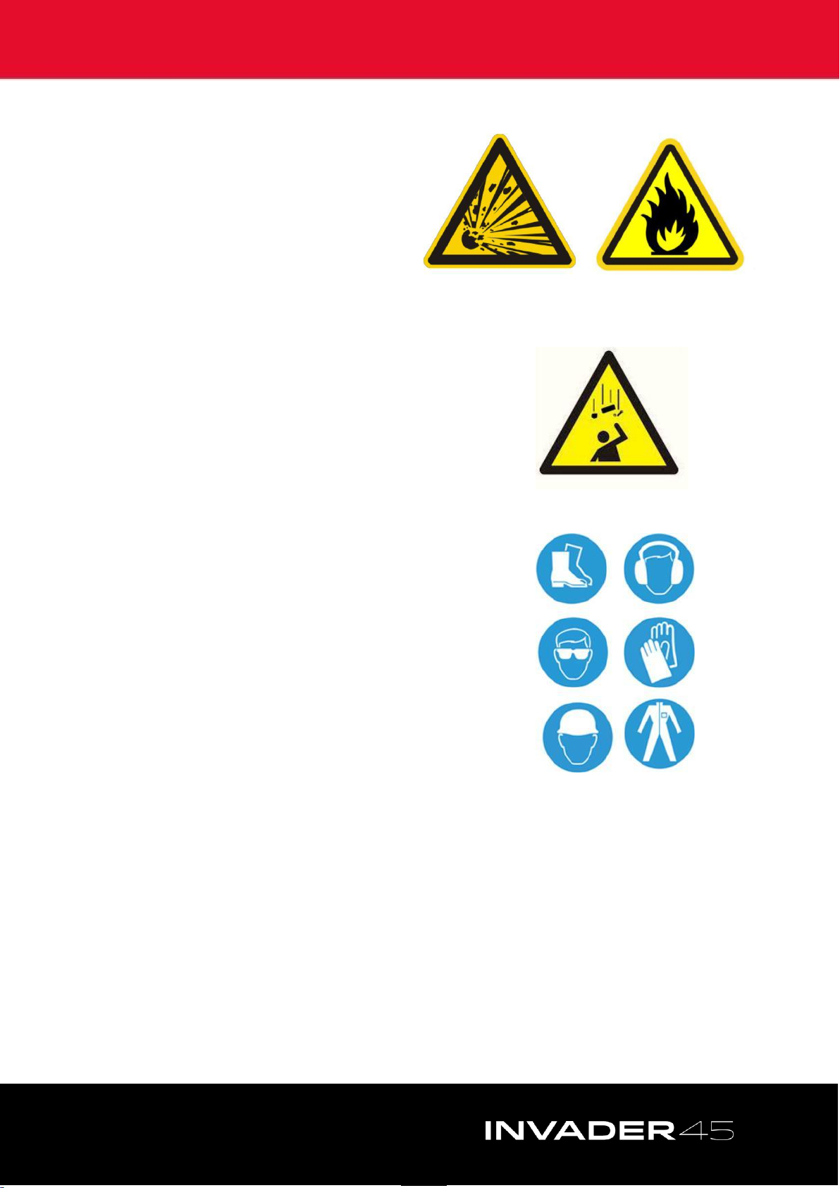
Coveya INVADER 45 User manual

OPERATION MANUAL
INVADER 45
3.0m, 4.0m, 6.0m

2
CONTACT US
Coveya Ltd
St Ivel Way
Bristol, UK
BS30 8TY
+44 (0) 117 956 3131
The manufacturer does not accept responsibility for any loss, damage to other equipment, injury to personnel or any other
circumstance resulting from the use of our equipment. All rights reserved. No part of this publication may be reproduced, stored in
a retrieval system, or transmitted in any form or by any means - electronic, mechanical, photocopying, recording or otherwise -
unless the permission of the publisher has been given beforehand. © All specifications are subject to change without notice

3
OPERATION MANUAL
CONTENTS
1. KNOW YOUR CONVEYOR ………………….. 4
2. CONTROLS…………………………………………. 5
3. SAFETY………………………………………….…… 6
4. PRE-START CHECKS & INSPECTION ……. 8
5. CONDITIONS OF USE……….………………… 10
6. FUNCTIONALITY CHECKS…………………… 11
7. OPERATING INSTRUCTIONS………………. 12
8. MAINTENANCE CHECKS………………….… 13
9. TRANSPORTATION…………….……………… 14
10. PARTS…………………………………………..….. 15
11. SPECIFICATIONS…………………………….… 18

4
1. KNOW YOUR CONVEYOR
1. Drive Drum
2. Lifting Handles
3. Scaffold Holes
4. Wheeled Undercarriage
5. Pneumatic Wheels
6. Undercarriage Release Latches
7. Forklift Holes
8. Belt Tensioning Points
9. Hopper Release Latches
10. Feed Hopper
11. Control Box
12. Conveyor Belt
1
2
3
4
5
6
7
8
9
11
10
12

5
2. CONTROLS
1. Power Supply Out (for additional conveyors)
2. Start Button
3. Emergency Stop Button
4. Stop Button
5. Power Supply In
6. Control Box Fixing Screws
1
2
3
4
5
6

6
3. SAFETY
FAILURE TO FOLLOW THE INSTRUCTIONS AND SAFETY ADVICE IN THIS
MANUAL COULD RESULT IN DEATH OR SERIOUS INJURY.
Do Not Operate The Conveyor Unless You:
1. Have read and understand the principles relating to the
safe operation of your conveyor contained in this
manual.
2. Avoid hazardous situations.
3. Always check the conveyor/s before every use.
4. Inspect the workplace for hazards.
5. Only use the conveyor for the purpose it is intended.
6. Are properly trained to safely operate the conveyor.
HAZARDS –Set-up
Make sure that the work area is free of any overhead obstructions and any other
hazards such as unstable ground or other work activities taking place.
Do not use the conveyor if you are under the influence of alcohol or drugs or
prescribed medication that may affect your judgement.
Assess suitability of the ground surface condition prior to conveyor set-up.
Ensure the conveyor is adequately supported and wheels are braked/chocked
before use.
Do not alter or disable the conveyor components with items that in any way affect
safety and stability.
Do not ride on the belt.
Do not operate in high winds or adverse weather conditions
Inspect the undercarriage wheels to ensure the tyres are in good condition.
Do not alter or disable the control box, motor, power leads or plugs without prior
consultation with the manufacturer.
HAZARDS - Electrocution
The conveyor is not electrically insulated and will not
provide protection from contact with or proximity to
electrical current.
Do not use if cables are damaged
Do not operate during lightning or storms.
Do not use the conveyor as an earth for welding.
Ensure safe routing of power cable to minimise risk of
electrocution.

7
HAZARDS - Explosion and Fire
Do not operate the conveyor in
locations which are hazardous
where potentially flammable or
explosive gases may be present.
HAZARDS –Fall
Do not allow access to the underside of the belt
whilst in use, without suitable protection in place –
material can drop from the belt and cause injury.
Do not lean over the conveyor while the belt is
moving.
Do not ride on the conveyor.
HAZARDS - Bodily Injury
Take care when planning the installation and
operating the conveyor.
Keep hands and limbs away from moving
components.
Always wear correct PPE.
HAZARDS –Damage to Conveyor or Components
If you are using a generator, make sure it is fitted with a voltage regulator.
Do not over load the conveyor - 200kg MAX belt load.
Do not use the conveyor if it is damaged or malfunctioning.
Carry out a thorough inspection before operating the conveyor and check everything
is functioning
Ensure that any maintenance specified in this manual is carried out at regular
intervals by competent personnel.
Make sure that all identification labels and serial number plates are present and
readable.

8
4. PRE-START CHECKS & INSPECTION
It is the responsibility of the operator to visually check the conveyor and surrounding area
before starting the conveyor. This should be carried out before each work shift.
A damaged or modified conveyor should never be used. If any damage or modification is
found, the conveyor should be disconnected from the power, tagged and removed from
service.
The following components or areas should be inspected for damage, modifications and
improperly installed or missing parts:
1. Electrical Components.
2. Wiring.
3. Power Sockets.
4. Motor and Gearbox.
5. Conveyor Frame.
6. Conveyor Feed Hopper.
7. Belt Condition.
9. Any hoarding to protect public areas.
10. Conveyor Wheeled Undercarriage or Supports.
The following components should be checked for
operational functionality:
1. Belt tension & tracking.
2. If a plough belt scraper is fitted, check it is making adequate contact with the
belt.
3. Emergency Stops are operating.
The following areas should be checked for cleanliness:
1. Material jammed between belt & conveyor frame.
2. Build up on slider beds.
3. Area under and adjacent to the loading/tail section.
4. If the conveyor is on a scaffold –ensure the area underneath the conveyor is
clear of any debris.

9
Do not operate the conveyor unless you have read and understood the instructions.
The operating instructions section provides instructions for the safe use of the conveyor. It
is the responsibility of the operator to follow all the safety rules and instruction provided in
this manual.
Only trained personnel should use the conveyor.
1. Fit the hopper to the loading end of the
conveyor. Align the locating posts and
secure the hopper to the conveyor by
means of the two over-centre catches.
2 Lift the loading end of the conveyor using the two carrying
handles and position the wheeled undercarriage in the centre of
the conveyor.
3. Secure in place tightening the
four over-centre catches.
4. Wheel the conveyor in to place using the handles at the top of the conveyor. If lifting of
the conveyor is required, make sure this is carried out using proper manual handling
procedures.
5. Subject to what voltage you are running on and the power supply, it is possible to run a
number of conveyors linked together.
When using more than one conveyor, setup the first conveyor and work forwards. When
you are happy with the placement, link the conveyors with the appropriate power leads.

10
5. CONDITIONS OF USE
Electrical Supply
●A constant 110v supply is critical for operation
●If operating from a generator ensure that this is rated at 10KVA or if using a
transformer use minimum 5KVA
●Ensure supply lead is a maximum length of 10m
Range of Intended Environmental Conditions:
Do not use the conveyor outside the following environmental conditions:
●Ambient temperature: -10°c -+40°c
●Wind Speeds: 0 –50MPH
Prohibited Applications
Do not use the conveyor if any part is:
●Submerged in water.
●In an explosive atmosphere.
●In a corrosive atmosphere or environment.
Prohibited Materials
●Solely Liquids.
●Reinforcing bar or metal rod.
●Items longer than 500mm.
●Lumps weighing greater than 30kg or measuring greater than 300mm x 200mm x 200mm.
●Heated materials above 60°c.
●Substances corrosive to rubber or metal.
●Materials likely to puncture the belt.
●Polymers or lubricating substances.
●Asphalt or adhesive substances likely to stick to the conveyor following use.
Conveyor Sound Levels:
●Decibel Rating 60-65db
.

11
6. FUNCTIONALITY CHECKS
Red Stop Button Emergency Stop Green Start Button
Emergency Stop
1. Press the green start button –the belt should move forwards
2. Press the emergency stop button –the belt should stop straightaway
3. Twist the Emergency Stop Button to reset
Stop/Start
4. Press the green start button –the belt should move forwards
5. Press the red stop button –the belt should stop straightaway
Voltmeter
If your conveyor is supplied with a Voltmeter, once power supply is connected the
screen will display what your supply voltage is.
IF THE CONVEYOR FAILS ANY OF THESE TESTS, IT SHOULD BE TAKEN OUT OF
SERVICE AND REPAIRED.

12
7. OPERATING INSTRUCTIONS
Start Up Procedure
1. Connect power lead to Control Box.
2. Switch on Power supply.
3. Check that the discharge area is clear.
4. Ensure nothing is leaning on the conveyor or likely to interfere with the belt
running.
5. Give audible warning and press the green start button on the Control Box.
6. Test emergency stop button by pressing/pulling it and checking belt stops.
Release button and begin operation.
Loading Methods
The conveyor must only be loaded at the hopper or at designated loading points.
Loading must only commence once conveyor has been started.
The conveyor must be loaded evenly and smoothly
Remember you are feeding a moving belt, so feed accordingly and the conveyor will
work well.
Ineffective loading or overloading can cause material to spill off the sides of the
conveyor and build up around the conveyor. This can in turn get into the conveyor
frame and jam the conveyor or damage the bearings.
When loading steeper conveyors some rollback will occur. Care must be taken to
ensure injury cannot be caused to the operator or others by large lumps coming back
down the belt. One way to reduce this risk to fit baffles above the belt to break the
fall of rolling back lumps.
If using a machine to load the conveyor ensure that it has a bucket with a maximum
width of 450mm.
Stopping Procedure
1. Ensure belt is emptied, except in emergency stop conditions.
2. Press the red stop button.
3. Power down the Control Box and remove the power lead.
OVERLOADING WILL INEVITABLY CAUSE
JAMMING AND BREAKDOWNS, THEREFORE
CAUSING DOWNTIME ON SITE.

13
8. MAINTENANCE CHECKS
Belt Tension and Tracking:
Maintaining the proper belt tension is an important part in keeping your conveyor
performing well and minimises the likelihood of breakdown. Operating the conveyor
with an improper belt tension can cause damage to conveyor components.
The only tool required for tensioning and tracking is a 19mm socket.
Check Belt Tension Whilst Power Is Off.
1. The belt will only need to be tensioned if it is slipping under load.
2. At the Tail end of the conveyor, tighten the two 12mm stud bolts holding the
tail drum to increase tension.
3. Apply tension evenly to each side.
4. Turn on conveyor and repeat the process until the belt stops slipping.
5. Observe the belt tracking.
6. Tracking at the Head of the conveyor is corrected via 1 x M12 Bolt on the
Head end of the conveyor.
7. Tracking at the Tail of the conveyor can be corrected via the M12 stud bolts
used for belt tensioning.
Check Belt Slider Bed Condition:
Ensuring no muck or debris is built up on or around the slider bed is essential to ensure good
performance and service life.
Check belt slider bed whilst power is off.
1. Lift belt at base and top of conveyor.
2. Inspect the condition of slider bed.
3. Move along the conveyor checking the bed is free of debris or build up.

14
9. TRANSPORTATION
Each Invader conveyor has forklift holes to facilitate safe lifting with forklift truck.
Ensure transport vehicles are parked on a level surface.
Remove wheeled undercarriage and feed hopper and transport these separately.
SECURING THE CONVEYOR FOR TRANSPORT:
Conveyors are stackable and have locating points at
each end of the conveyor.
Inspect the conveyor for loose or unsecured items
prior to stacking.
ENSURE STRAPS ARE NOT OVER TIGHTENED
Excessive tensioning of straps will cause damage to the conveyors.

15
10. PARTS
CONVEYOR
501027
3.0m Slider Bed
501036
Head Tracking Bracket
500864
4.0m Slider Bed
500361
Tension Plate RH
501029
6.0m Slider Bed (Qty 2)
500362
Tension Plate LH
501045
Slider Bed Curved End - Drive
500353
Tail Drum
501452
Slider Bed Curved End - Feed
501308
Tensioning Stud
500320
Drive Drum
501474
Rectangular Nut
501461
Drive Shaft
500337
Plastic Return Support
500324
Drive Plate RH
500338
Return Cross Member
500325
Drive Plate LH
502028
Forklift Protector Plate
500327
Head Straight Cross Support
501086
Internal Scraper Blade
500356
Handle
502023
Cross Brace Strengthener

16
HOPPER
500438
Hopper Back
500445
Hopper Side Rubber Clamp
500439
Hopper Side RH
500778
Hopper Locator
500441
Hopper Side Support
501087
Hopper Side Rubber LH
500443
Hopper Back Rubber Clamp
501088
Hopper Side Rubber RH
500444
Hopper Back Rubber
EWL70
Hopper Latch

17
WHEELED UNDERCARRIAGE
500355
Undercarriage Frame
501077
Wheel Shaft (Qty 2)
501054
Undercarriage Cross brace
821217S
Undercarriage Wheel
EWL70
Undercarriage Latch

18
11. SPECIFICATION
Frame Size
3.0m
4.0m
6.0m
Length
3000mm
4000mm
5800mm
Width
590mm
590mm
590mm
Height
350mm
350mm
350mm
Hopper Size
650 x 800mm
650 x 800mm
650 x 800mm
Weight
130kg
160kg
200kg
Specifications
Belt Speed
0.75m/s (45m/min)
Belt Width
450mm
450mm
450mm
Belt Load
200kg
200kg
200kg
Tons per Hour
150 t/h
150 t/h
150 t/h
Voltage
110/230V
110/230V
110/230V
Motor
1.5kw
1.5kw
1.5kw
Maximum Angle
400
400
400
Max Discharge Height
1885mm
2525mm
3715mm
Table of contents
Other Coveya Accessories manuals
Popular Accessories manuals by other brands

PCB Piezotronics
PCB Piezotronics ICP W112A21 Installation and operating manual

Loadrite
Loadrite Force Operator's manual

Makita
Makita CJ105D instruction manual

Balluff
Balluff IO-Link BLA D Series user guide

Nobile
Nobile Smartmatic Ambient Mounting Operation Instruction

Manitowoc
Manitowoc K00108 installation instructions