CoVi EVQ-3000 User manual

Quick Install Guide for the CoVi EVQ-3000 Mini-Dome Camera
1
This Quick Install Guide describes how to install the CoVi EVQ-3000 Mini-Dome camera in Flush Mount, Surface Mount, and Vandal Resistant enclosures. For information about
configuring the camera with the CoVi Remote Camera Control Utility (RCCU) software, see the CoVi EVQ-3000 Product Guide.
GENERAL INSTALLATION REQUIREMENTS:
•Power supply: 12V DC (0.66 A) or a 24V AC
(0.33 A) rated at 8W or greater
•Appropriate lengths and types of power and
signal cabling for video, data, and power
•Appropriate adapters and conduit for local
regulations and codes
•Tools for mounting the dome, as necessary
•Cement anchor screws for cement surfaces
•(OPTIONAL; recommended) Junction box
(4” double-gang electrical box with a mud
ring or a ‘Bell’ box) for the breakout board
WARNING: To avoid the risk of personal injury and electrical shock, when
connecting power, disconnect the main power feed at the power panel either by
circuit breaker or by physically removing the main circuit wiring from AC power
distribution terminals.
CAUTIONS:
•To avoid personal injury or damage to the equipment, make sure the power panel
supplying power to the camera is reliably earth grounded.
•Installation and servicing should be done by qualified personnel and all work done
should conform to local codes.
•Using 3rd party replacement parts or accessories may invalidate the warranty.
•Make sure the installation surface can support 4x the weight of the complete
mini-dome assembly.
Installing the Flush Mount Mini-Dome(lay-in/drop ceilings)
PACKAGE CONTENTS (ALL PRODUCTS):
•BOX 1: Base housing, dome bubble, and fasteners
•BOX 2: Camera yoke assembly
•CABLING: 7-foot plug-and-play Cat. 5 flat cable with breakout board (dual video, power, RS-485 connections) and mounting screws
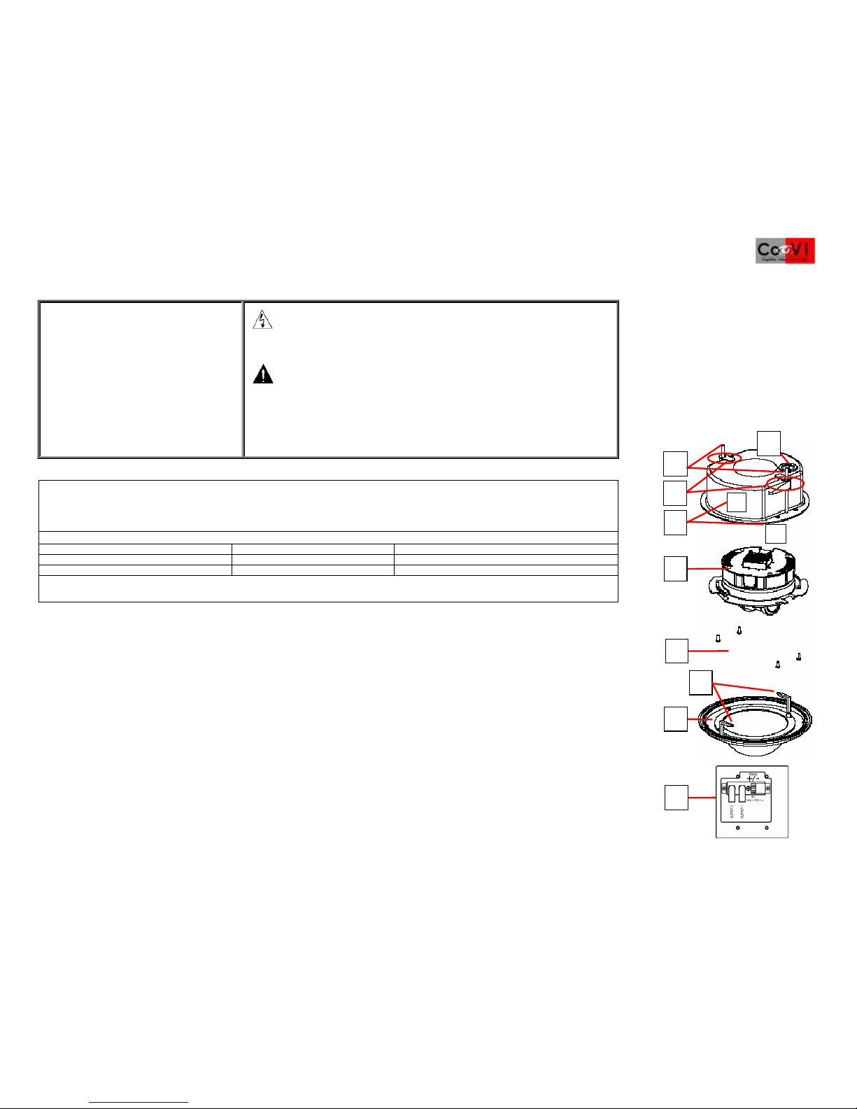
FLUSH MOUNT MINI-DOME COMPONENTS:
[1] Base mounting screws (2) [4] Top conduit opening [7] Mounting paddles (2)
[2] Anchor clips [5] Camera yoke assembly [8] Dome bubble
[3] Base housing center (a) and lip (b) [6] Yoke mounting screws (4)
[9] Breakout board (mounted to junction box cover): Contains RJ-45, RS-485, two BNC video, power connections.
IMPORTANT: We recommend that you install a 4” double gang box with a mud ring or weatherproof “Bell” box to protect the breakout board.
1. Read the section “GENERAL INSTALLATION REQUIREMENTS” to ensure they are met.
2. Read the WARNINGS and CAUTIONS.
3. Remove the dome bubble [8] from the base housing [3] by twisting the dome counter clockwise. A mounting strap secures the dome
bubble to the base. Carefully move the dome bubble to the side or unscrew the strap and remove the dome bubble. To ensure the dome
bubble is not scratched or damaged, keep the protective plastic on it until ready for use.
4. Remove the camera yoke assembly [5] from its box and keep in a safe place until ready to install. See the section “Installing the Camera
Yoke Assembly” in this Quick Install Guide.
5. Find the desired mounting location, using the base mounting screws [1] for the mounting location and the base housing [3] as a cutting
template.
6. (OPTIONAL) If conduit is not used, install the plastic grommet (provided, not shown) in the top entry opening [4] of the base housing [3].
7. Mark and cut a hole the size of the base housing center [3a] (approximately 5.65” [143mm] in diameter) and place the base housing
through this hole. The base housing lip (3b) should be flush with the outside mounting surface.
8. Use a Phillips head screwdriver to adjust the space between the anchor clips and base housing.
9. Tighten the base mounting screws [1] until the anchor clips [2] are snug to the back of the mounting surface. Do not over tighten.
10. Pull flat Cat. 5 cable through the top conduit opening [4].
11. You are now ready to install and configure the camera yoke assembly [5]. See the section “Installing the breakout board” and “Installing
the camera yoke assembly.”
5
6
9
8
4
7
1
3
2a
b

©2005-2008 CoVi Technologies, Inc. All rights reserved. CoVi, the CoVi logo, EVQ-3000, MultiView, and ZUP are trademarks of CoVi Technologies, Inc. CoVi Technologies, Inc. has made every effort to identify trademarked properties and
owners on this page. All brands and product names used in this document are for identification purposes only and may be trademarks or registered trademarks of their respective companies. January, 2008 P/N 1DOC 0001022-01 Rev. 4 2
Installing the Surface Mount Mini-Dome(lay-in/drop ceilings)
IMPORTANT: This section describes installing the EVQ-3000 Surface Mount Mini-Dome. See the CoVi EVQ-3000 Product Guide
for information about using the CoVi Remote Camera Control Utility (RCCU) software.
PACKAGE CONTENTS (ALL PRODUCTS):
•BOX 1: Base housing, dome bubble, and fasteners
•BOX 2: Camera yoke assembly
•CABLING: 7-foot plug-and-play Cat. 5 flat cable with breakout board (dual video, power, RS-
485) and mounting screws
SURFACE MOUNT MINI-DOME COMPONENTS:
[1] Toggle bolt fasteners (2) [6] Base housing
[2] Dome cover [7] Camera yoke assembly
[3] Cable opening (in base housing) [8] Yoke mounting screws (4)
[4] Base mounting screws [9] Dome assembly
[5] Bolt guides [10] Mounting paddles
[11] Breakout board (mounted to junction box cover): contains RJ-45, RS-485, two BNC video,
power connectors. IMPORTANT: We recommend that you install a 4” double gang box with a mud
ring or weatherproof “Bell” box to protect the breakout board.
1. Read the “GENERAL INSTALLATION REQUIREMENTS” to ensure they are met.
2. Read the WARNINGS and CAUTIONS.
3. Remove the dome assembly [9] from the base housing [6] by twisting the dome counter clockwise. A mounting strap secures
the dome bubble to the base. Carefully move the dome bubble to the side or unscrew the strap and remove the dome bubble.
To ensure the assembly dome bubble is not scratched or damaged, keep the protective plastic on it until ready for use.
4. Remove the camera yoke assembly [7] from its box and keep in a safe place until ready to install. See the section “Installing the
Camera Yoke Assembly” in this Quick Install Guide.
5. Find the desired mounting location, marking the holes for installation using the bolt guides [5] as a drilling template.
6. Thread the base mounting screws [4] through the bolt guides [5].
7. Drill two 3/8” diameter holes in the mounting surface to mount the base housing.
8. Insert the plastic grommet (provided, not shown) into the cable opening [3] of the base housing.
9. Install the dome cover [2] by aligning the two mounting screws [4] with the corresponding holes and then pushing the dome
cover over the base housing [6].
10. Hand-thread the toggle bolt fasteners [1] onto the base mounting screws [4]. Finish tightening them with a Phillips head
screwdriver. This assembly should be snug to the back of the mounting surface.
11. Pull flat Cat. 5 cable through the cable opening [3].
12. You are now ready to install and configure the camera yoke assembly [7]. See the sections "Installing the breakout board" and
"Installing the camera yoke assembly."
3
5
9
2
7
4
8
10
11
1
6

Quick Install Guide for the CoVi EVQ-3000 Mini-Dome Camera
3 ©2005-2008 CoVi Technologies, Inc. All rights reserved. CoVi, the CoVi logo, EVQ-3000, MultiView, and ZUP are trademarks of CoVi Technologies, Inc. CoVi Technologies, Inc. has made every effort to identify trademarked properties and
owners on this page. All brands and product names used in this document are for identification purposes only and may be trademarks or registered trademarksof their respective companies. January, 2008 P/N 1DOC 0001022-01 Rev. 4
Installing the Vandal Resistant Mini-Dome(hard ceilings or walls)
IMPORTANT: This section describes installing the EVQ-3000 Vandal Resistant Mini-Dome. See the CoVi EVQ-3000 Product Guide
for information about using the CoVi Remote Camera Control Utility (RCCU) software.
PACKAGE CONTENTS (ALL PRODUCTS):
•BOX 1: Base housing, dome bubble, and fasteners
•BOX 2: Camera yoke assembly
•CABLING: 7-foot plug-and-play Cat. 5 flat cable with breakout board (dual video, power, RS-485) and
mounting screws
VANDAL RESISTANT MINI-DOME COMPONENTS:
[1] Base housing [2] Side entry (vandal resistant)
[3] Yoke mounting screws (4)
[4] Camera locking slots (4)
[5] Camera yoke assembly
[6] Dome bubble
Exploded base housing assembly:
[A] Metal entry plug
[B] Top conduit opening
[C] Mounting holes (4)
[D] ½-inch conduit connector
[E] Side conduit opening [7] Tamper-proof base mounting screws (4)
[8] Breakout board (mounted to junction box cover): contains RJ-45, RS-485, two BNC video, power connectors.
IMPORTANT: We recommend that you install a 4” double gang box with a mud ring or weatherproof “Bell” box
to protect the breakout board.
1. Read the section “GENERAL INSTALLATION REQUIREMENTS” to ensure they are met.
2. Read the WARNINGS and CAUTIONS.
3. Carefully remove the dome bubble [6] from the base housing [1]. NOTE: The bubble is not attached to the base with mounting
straps. Keep the protective plastic on the dome bubble to ensure the it is not scratched or damaged until ready to use.
4. Remove the camera yoke assembly [5] from its box and keep in a safe place until ready to install. See the section “Installing
the Camera Yoke Assembly” in this Quick Install Guide.
5. Pull flat Cat. 5 cable through the top [B] or side conduit opening [E]. (Because of the elastomer liner on the base housing, the
top conduit opening [B] as well as the mounting holes [1B] can only be seen from inside the dome.)
6. Find the desired mounting location, using the four mounting holes [C] inside the base housing as a drilling template (see Inset).
7. Mount the base housing to the mounting surface using the screws and fasteners provided. OPTIONAL: Mount this to a junction
box (not provided).
8. (OPTIONAL if using the side conduit opening [E]) Remove the metal entry plug [A] from the side conduit opening [2] and install
the ½-inch conduit connector [D].
9. Install the four camera mounting screws [3] in the base housing [1]. Do not tighten them. They lock into camera locking slots [4].
(See Step 10.)
10. You are now ready to install and configure the camera yoke assembly [5]. See the sections "Installing the breakout board" and
"Installing the camera yoke assembly."
6
2
7
8
3
5
4
A
1
D
B
C
E

©2005-2008 CoVi Technologies, Inc. All rights reserved. CoVi, the CoVi logo, EVQ-3000, MultiView, and ZUP are trademarks of CoVi Technologies, Inc. CoVi Technologies, Inc. has made every effort to identify trademarked properties and
owners on this page. All brands and product names used in this document are for identification purposes only and may be trademarks or registered trademarks of their respective companies. January, 2008 P/N 1DOC 0001022-01 Rev. 4 4
Breakout board connections
NOTE: These steps assume the breakout board is already installed in a 4” double gang box with a mud ring or in weatherproof ‘Bell” box to protect it.
The diagram shows how to connect power and Ethernet cables between the EVQ-3000 and the Breakout Board and to the video outputs.
1. Connect 24V AC or 12V DC to the breakout board power terminals [1]; the breakout board power LED should be ON.
2. Connect a Cat. 5 or Cat. 5e cable between the Dome Camera and the Breakout Board [2].
3. Terminate the coax cable(s) from OUTPUT 1 (BNC connectors on the breakout board [3]).
4. Install the camera in the base housing by fitting the four camera slots [4] over the screws on the base housing and turning the assembly clockwise.
5. Tighten the yoke assembly to the base.
Video setup and focusing
You can focus the camera in several ways depending on the equipment available.
1. To begin, remove the lens cover and fully open the iris on the lens.
2. Select from one of the following options for video setup:
•Handheld Monitor
•RS232-to-RS485 converters and a PC
•Camera Programmer
3
1
2
4

Quick Install Guide for the CoVi EVQ-3000 Mini-Dome Camera
5 ©2005-2008 CoVi Technologies, Inc. All rights reserved. CoVi, the CoVi logo, EVQ-3000, MultiView, and ZUP are trademarks of CoVi Technologies, Inc. CoVi Technologies, Inc. has made every effort to identify trademarked properties and
owners on this page. All brands and product names used in this document are for identification purposes only and may be trademarks or registered trademarksof their respective companies. January, 2008 P/N 1DOC 0001022-01 Rev. 4
Video setup and focusing: Handheld Monitor
Use the diagram below to connect the EVQ-3000 Dome Camera through the RCA jack to a handheld monitor (purchased separately from a 3rd-party vendor). Then, manually focus
and pan, tilt, and rotate the camera for optimal image quality.

©2005-2008 CoVi Technologies, Inc. All rights reserved. CoVi, the CoVi logo, EVQ-3000, MultiView, and ZUP are trademarks of CoVi Technologies, Inc. CoVi Technologies, Inc. has made every effort to identify trademarked properties and
owners on this page. All brands and product names used in this document are for identification purposes only and may be trademarks or registered trademarks of their respective companies. January, 2008 P/N 1DOC 0001022-01 Rev. 4 6
Video setup and focusing: RS-485 connection to a PC
Use the diagram below to connect the Dome Camera to a PC through an RS232-to-RS485 converter (purchased separately from a 3rd-party vendor).
NOTE: Although other converters are available, the one shown is the B&B Electronics (www.bb-elec.com) RS-485 Converter (Model 485PTBR). See the information below about
possible need for a 12 volt power supply for the converter. Once the PC is set up, manually focus and pan, tilt, and rotate the camera for optimal image quality.

Quick Install Guide for the CoVi EVQ-3000 Mini-Dome Camera
7 ©2005-2008 CoVi Technologies, Inc. All rights reserved. CoVi, the CoVi logo, EVQ-3000, MultiView, and ZUP are trademarks of CoVi Technologies, Inc. CoVi Technologies, Inc. has made every effort to identify trademarked properties and
owners on this page. All brands and product names used in this document are for identification purposes only and may be trademarks or registered trademarksof their respective companies. January, 2008 P/N 1DOC 0001022-01 Rev. 4
Video setup and focusing: Camera Programmer
Use the diagram below to connect the Dome Camera to the Camera Programmer (purchased separately from CoVi). The Camera Programmer is used for remote configuration via
serial RS-485 and uses Pelco P preset commands to select or toggle configuration parameters.

©2005-2008 CoVi Technologies, Inc. All rights reserved. CoVi, the CoVi logo, EVQ-3000, MultiView, and ZUP are trademarks of CoVi Technologies, Inc. CoVi Technologies, Inc. has made every effort to identify trademarked properties and
owners on this page. All brands and product names used in this document are for identification purposes only and may be trademarks or registered trademarks of their respective companies. January, 2008 P/N 1DOC 0001022-01 Rev. 4 8
Setting the Camera ID
Set the camera ID using the dip switches on the camera, shown in the illustration. (See the CoVi EVQ-3000 Installer’s or Product
guides for dip switch settings.)
•Switches 1-8 (left to right)—Set camera RS-485 address 0-255 (default=1)
•Switch 9—NTSC (OFF/DOWN), PAL (ON/UP) setting (default=DOWN/NTSC)
•Switch 10—Sets the RS-485 connector to either termination mode (OFF/DOWN/LOW) or daisy chain mode (ON/HIGH/UP)
(default=DOWN/termination mode)
NOTE: “CTS” is the manufacturer’s name and not a dip switch setting.
Complete the camera and dome installation
1. After setting up the camera yoke assembly, reinstall the dome bubble on the dome cover assembly with the screws provided (use the tamper-proof screws and hex tool
provided for the vandal-resistant dome).
2. Adjust the included inner liner to conceal the camera position.
After camera installation
See the CoVi EVQ-3000 Product Guide for configuration options using CoVi RCCU software.
CoVi Technologies, Inc.
6300 Bridgepoint Parkway
Suite 300, Building II
Austin, Texas 78730
888-987-2684 (toll free, Support)
512-527-5900 (local and
international)
ON
OFF
Table of contents