Cowlacious Designs Scary Terry ST-400 User manual
Scary Terry’s Audio
Servo Driver™
ST-400 Rev.1 Circuit Board
Cowlacious Designs™
By Computer & Electronic Services

2
Index:
Introduction pg. 2
Overview pg. 3
Testing and Adjustments pg. 4
Using a Microphone pg. 6
Optional Devices pg. 7
Introduction:
Scary Terry has allowed us at Computer & Electronic Services to produce a
Cowlacious Designs circuit board from his original design. Over the years
we have changed it a little bit, but the main circuitry is still Terry’s! We thank
him for the great circuit he designed for everyone to enjoy!
Scary Terry describes the circuit as follows:
“My goal in creating this was for a simple, inexpensive and reliable circuit
that doesn't require programming a microcontroller for each individual
movement. I've used several of these circuits over the last couple of Hal-
loween's to drive Bucky (skeleton skull) and other animatronic heads, and
they worked all night long without fail.”
“As long as there is sound present, the servo will drive to its "max" position.
If the sound is short in duration, the servo will not have time to drive to
"max" but will drive part way and return to "min" position. While this method
of moving a mouth is not perfect, it's pretty good and I'm very happy with
the effect. It's important to remember that any sound will drive the servo,
voice, music or noise, so if you're trying to make a Bucky mouth move to a
voice track, you shouldn't have music in the background of that particular
track.”
Terry’s web site is:

3
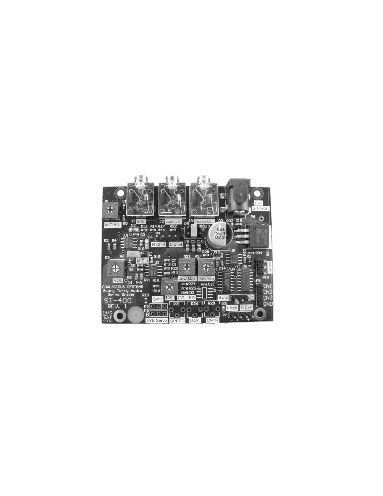
MiC Input
(PC microphone)
MIC Sensivity
Adjustment
Line In Jack
Line Out Jack Power Connector
Power Indicator
LED
Response Time
Adjustment
Header
Servo Connec-
on
High current
device connec-
on, i.e.; sole-
noid, motor,
lights.
Connecon for
Eye LED cables.
White is posive.
Input Volume
Adjustment
Trigger Volume
Level Adjustment
Trigger Level
LED
Shorng this
header sends
MIC audio to
circuit. Never
use MIC and
Lin In at the
same me!
Set the maxi-
mum the jaw
will open. This
must be done
while the LVL
LED is on.
Set the closed
posion of the
jaw. This must
be done with
the LVL LED o.
Selects the Audio
Channel(s) used for
driving the servo.
ST-400 Rev. 1 Overview

4
Testing and Adjustment
(Note: Please see connection diagrams on the following pages.)
Connect your servo to the servo header. Make sure you properly orient your servo
connector with the header. The header is marked with “Y R B”, where Y is for
Yellow, R is for Red or positive, and B is for Black or Negative. (Colors for the
yellow wire will vary by servo manufacturer, but the Red and Black are usually
there.)
Supply power to the board through either the barrel connector (P6) . You should
see the “PWR” LED light up as soon as power is applied.
Adjust the threshold level, “LVL” pot (R18) clockwise until the “LVL LED” turns on
and then stop the adjustment. Then, adjust the “Jaw Max” pot to set the maxi-
mum you would like the jaw to open. Adjust the “LVL” pot back until the “LVL
LED” turns off. Then, adjust the “Jaw Min” pot until the jaw closes to desired po-
sition when no audio is playing.
Finally, adjust the “LVL” pot until the “LVL LED” is on and then back it off just a
little until the “LVL LED” turns back off. This is a critical adjustment is very sensi-
tive. Turn the pot slowly and in very small increments.
This control is used to adjust how loud the sound needs to be before the servo
will start to move. If it is set too low the servo will remain at its maximum position
too much of the time. If it is set too high the servo will not respond to the sound
at all or not as much as desired.
Audio can be fed to the circuit from a line-level source (MP3 player, CD player, or
one of our CAR/P or CAP audio boards).
Using a Line Level Audio Source
Feed audio to the circuit through the 3.5mm stereo “Audio In” jack. If you want both
channels of sound to control the ST-400 then make sure that the red shorting jumpers
are on RChnl and LChnl. If you want only the right channel to control the ST-400 then
remove the shorting jumper from LChanl and make sure a red shorting jumping is on
RChnl. If you want only the left channel to control the ST-400 then remove the short-
ing jumper from RChanl and make sure a red shorting jumper is on LChnl.

5
PLEASE NOTE: Both channels of the audio are always passed on to the “Audio
Out” jack. The “Audio Out” jack can connect to an external set of powered comput-
er speakers, powered MP3 speakers, or it can feed the Aux or Line-In jack of an
amplifier that has speakers connected to it.
Adjust the “VOL” pot until you get the kind of response you want. Remember, this
circuit is designed to move the servo to its maximum position whenever audio is
present. If the audio is too loud it will remain in its maximum position until the
“VOL” is adjusted to an appropriate audio level.
If you want the audio level up at a higher level for the output side of things, ad-
just the audio level to its desired position then adjust the “LVL” until you get the
response you want.
The “VOL” adjustment and the “LVL” adjustment work in conjunction with each
other, so you may need to experiment a little bit with these controls to get the ef-
fect you want from the sound source you are using.
OTHER AJUSTMENTS AND CONNECTIONS
There are three header pins on P5 with a red removable jumper across the two
middle pins. This header allows you to fine tune how quickly the circuit responds
to sounds. In the middle position it is using a 4.7uF capacitor. If you move the
jumper up two pins it will use a 2.2uF capacitor, speeding the reaction time up a
little. If you move the jumper to the down two pins it will be using a 10uF capaci-
tor which will slow the reaction time down a little.
High Current Section (P9)
The high current driver of the Scary Terry board allows the board to control de-
vices such as small DC lamps, relays, and solenoids for air and water. This sec-
tion can be used to control props that require larger eyes than LED’s and/or to
control a jaw that is just too big for a servo to be able to control.
Each of the 3 channels is capable of sinking 500mA of current. We don’t recom-
mend pushing it that hard without attaching a heatsink to the chip, but that is
what the specs for the device say.
The chip can sink up to 24VDC devices, even though the Scary Terry board is
only a 5VDC board.

6
Using A Microphone
You can use a PC or headset type electret condenser microphone with this product to control the jaw move-
ment.
To use a mic:
Make sure no audio cables are plugged into the Line In jack.
Power up the board as you normally would.
Move the red shorng jumper on “MIC J” (P1) so that it shorts (is over) both pins of the “MIC J” header.
Plug your microphone into the “MIC” (J1) jack and begin to speak.
You may need to adjust the “MIC Adj” (R1) pot to increase or decrease the microphones sensivity. You
may also need to adjust the “VOL” and “LVL” pots to get the board to react in the desired manner.
NOTE: Please remember to remove the shorng jumper from the “MIC J” posion if you decide to go back to
using the Audio In jack.

7
SUPPLIED DEVICES
LED AUDIO EYES
The L Eye & R Eye connections can be set so that the LED Eyes are
always on or so that they flash with the audio. Setting the red shorting
jumper of P7 across the middle pin and the “On” pin will make the
eyes flash with the audio. Setting the red shorting jumper of P7 across
the middle pin and the left pin will make the eyes stay on continuously.
The LED eyes attach to the R Eye (P10) and L Eye (P9) headers with
the black wire facing towards + symbol. Our LED Audio Eyes can
simply be plugged onto these connectors.
Just about any color LED will work fine with these connections (clear
ultrabright red LED’s are supplied).
3.5MM TO 3.5MM 6’ STEREO CABLE
OPTIONS AVAILABLE FOR PURCHASE
Please see our web site at www.cowlacious.com
9VDC, 500MA, WALL TRANSFORMER THAT PLUGS INTO THE BAR-
REL JACK.
HITECH 425BB SERVO
COMPUTER SPEAKERS
3.5MM TO RCA CABLE
HIGH CURRENT WIRING ASSEMBLY
The high current section on the board allows for higher current devices to be
controlled by the Scary Terry Audio Servo Driver board. This connection allows
devices such as small lamps, relays, and solenoids for air and water to be con-
trolled in sync with the audio, just like the LED Audio Eyes. These devices will
turn on and off in sync with the “LVL LED”.
The Wiring Assembly provides a four pin connector with 6” wires for making con-
nections to the circuit board header (P9) easier.

8
Special Thanks to Scary Terry (Terry Simmons) for letting us use
his original design for this product!
We hope you enjoy it!
Computer & Electronic Services
Cowlacious Designs
255 Distribution Dr. #203
Sparks, NV 89441
(775) 425-9151
www.cowlacious.com
Table of contents


