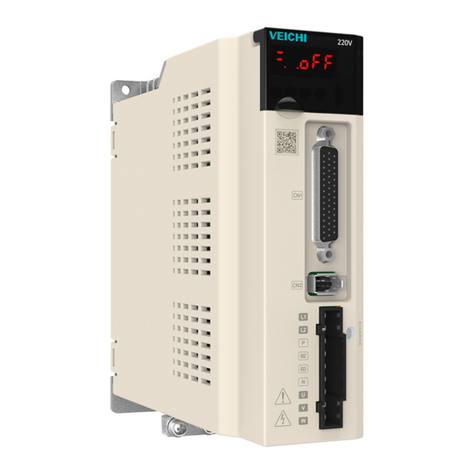
Veichi SD700 series User manual


1
Preface
Thanks for using SD700 seriesAC servo drive.
VEICHI SD700 series is the general purpose high performance servo drive which
adopts a series of advanced motor control algorithm and 24-bit high precision encoder,
featuring high control precision, fast tracking response, simple and convenient
debugging to meet the function and performance requirements in high-end general
purpose servo applications. Rich application functions such as built-in point control
function, electronic cam, RS485 interface, CANopen interface and 16-bit analog input
can provide high reliability and high cost performance solutions for machine tools,
electronic equipments, robots, textile applications, packaging industry and etc.
This manual is delivered with equipment and only introduces safety precautions,
installation and wiring, function code table, fault diagnoses and processing, monitoring
parameters and etc. For detailed function explanations and application specifications
please refer to SD700 series product instructions or consult VEICHI company.As it is
the basic guide for proper use and safe operation, please carefully read and keep it
and be sure to handle it to end users.
If any problems or special requirements, please feel free to contact our company,
dealers or the customer service center, we will provide dedicated service for you.
This manual is subject to change without notice, thanks for your kind support.

2
Safety Precautions
For safety concerns, please fully understand the safety requirements and cautions
before using.
Operational Qualifications
Only professional trained person are allowed to operate the equipment. In addition,
operators must undergo professional skills training and be familiar with the equipment
installation, wiring, operation and maintenance, and can correctly respond to various
emergency situations in use.
Safety Guidance
Safety regulations and warning signs come for your security. They are measures to
prevent the operator and machine system from damage. Please carefully read this
manual before using and strictly observe the regulations and warning signs while
operating.
●
Correct transport, store, installation and careful operation and maintenance are
important for servo system safe operation. In transport and store process,
make sure the servo system is free from impact and vibration. It must be stored
where is dry without corrosive air and conductive dust, and the temperature
bust be lower than 60℃。
●
This product carries dangerous voltage and controls driver machine with
potential danger. If you don’t abide by the regulations or requirements in this
manual, there is danger of body injury even death and machine damage.
●
Do not wire while the power is connected. Otherwise, there is danger of death
for electric shock. Before wiring, inspection, maintenance, please cut off power
supply of all related equipments and ensure main DC voltage in safe range.
And operate it after 10 minutes.
●
Power line, motor line and control line must be fastened.The grounding
terminal must be grounded reliably and the grounding resistance is less than
10Ω.
●
Human body static electricity will seriously damage the internal sensitive
devices. Before operation, please follow ESD measures, or there will be
danger of servo system damage.
●
As the output volatge of servo system is pulse weave, if components such as
capacitors for improving power factor or pressure-sensitive resistances for
anti-thunder are installed at the output side, please dismantle them or change
to input side.

3
●
No switch components such as breaker and contactor at the output side (if
necessary, please be sure the output current is 0 while the switch acting).
●
No matter where the fault is, there is danger of serious accident. So there must
be additional external prevent measures or backup device.
●
Only used in application fields as maker stated. No use in equipments related
to special fields such as emergency, rescuer, ship, medical treatment, avigation,
nuclear and etc.
●
Maintenance of this product can only be carried out by the company or the
authorized professionals, unauthorized modification or using non-approved
parts may lead to product faults.Any defective devices must be replaced in
time during maintenance.

4
Chapter 1 Installation and wiring
1.1 Installation Dimensions
Dimension
Structure Model Dimensions(mm)Installation dimensions (mm) Mou
nting
apert
ure
W H D W1 W2 H1 H2 A B
SIZEA SD700-1R1A-** 45 168 170 \ 20 160 \ 7.5 5 2-M4SD700-1R8A-**
SD700-3R3A-**
SIZE B
SD700-5R5A-**
71 168 180 58 58 160 \ 6.5 5 3-M4
SD700-7R6A-**
SD700-9R5A-**
SD700-2R5D-**
SD700-3R8D-**
SIZE C
SD700-160A-**
92.5 188 182 82.5 75 180 \ 5 5 3-M4
SD700-6R0D-**
SD700-8R4D-**
SD700-110D-**
SIZE D SD700-170D-** 120 260 210 100 84.5 250 236 \ \ 4-M5SD700-240D-**
SD700-300D-**

5
1.2 Main circuit terminal size
L1
L2
L3
L1C
L2C
B1
B2
B3
U
V
W
+
/
Main circuit interface
Pins
numb
er
Sign
nam
e Function
1 L1
Power input of the main circuit
Please determine whether the input power is 220V or 400V according
to the nameplate
220V models: 200V ~ 240V, -15% ~ +10% 50 / 60Hz
400V models: 380V ~ 440V, -15% ~ +10% 50 / 60Hz
Note: "L3" terminal, SD700-1R1A, 1R8A, 3R3A models are
single-phase inputs without this pin
2 L2
3 L3
4 L1C
Control power input
Power input requirements same with L1, L2, L3
5 L2C
6 B1/
+ Regenerative resistor connection terminal
SD700-1R1A, 1R8A, 3R3A. When regenerative braking capacity is
insufficient, connect an external regenerative resistor between B1 / +
and B2; other models remove short wiring or short connection between
B2 and B3, Connect an external regenerative resistor between B1 / +
and B2, The external regenerative resistor need be purchased
separately.
"B1 / +" terminals can be used for common DC bus positive power
supply terminals
Note: "B3" terminal, SD700-1R1A, 1R8A, 3R3A models without this pin
7 B2
8 B3
9 -
"-" terminal can be used for common DC bus negative power supply
terminals
10 U
Connect the U, V, W phase of the motor
11 V
12 W
13 Safe ground

6
1.3 CN1 Control Terminal
No.1
No.2
No.24
No.25
No.26
No.27
No.49
No.50
The appearance seen from the
arrow direction is shown below.

7
1.4 Position Control Wiring Diagram

8
1.5 Speed Control Wiring Diagram

9
1.6 Torque Control Wiring Diagram

10
1.7 Output Port Attentions
1.8 Brake Wiring
When servo motor is used for vertical axis situations, the brake can be used to
prevent or keep the falling speed of heavy loads when servo drive is in power off state.
Wiring diagram of electromagnetic brake is shown as below:
+
-
RY
12V~24V
SO1-
SO1+
Servo driver
+
-
Motor
Brake
winding
Surge
absorption
Fuse
(5A)
Power supply for
brake winding
Emergency
stop
RY
DC24V
Note: brake winding must use specialized 24V power supply, and
do not share power source with control power or RY relay coil.
Electromagnetic brake must be provided with a dedicated 24V power supply, be
prohibited to share power source with control signal;
means relay coil, please note the diode direction ;
Electromagnetic brakes are for holding and can not be used for normal parking;
Though electromagnetic brake has function to prevent or keep heavy objects from
falling, external braking devices are still necessary.
RY

11
1.9 CN2 Encoder Signal Terminal
B
A
123
4
5
6
78
9
21
43
65
Sign Define AEnd Pins Number BEnd Pins Number
+5V
0V
SD+
SD-
PE(Shield)
1
2
5
6
1
2
5
6
Iron Shell 7
Pins Define
BAT+ 3 3
BAT- 4 4
1.10 Motor Power Terminal
34
12
PE
W
V
U
Sign Define Terminals Pins Number
Pins Define
U2
V3
W4
PE 1
1.11 CN6A/CN6B Bus Communication Terminal
Pin 8
Pin 1
Pin 8
Pin 1
Port function table
Pin No. Name Function Remarks
1 CANH CAN Data+ CN6A and
CN6B has
exactly same
signal
distribution,
and the internal
parallel can
facilitate multiple
network
connections.
2 CANL CAN Data -
3 CAN
G CAN Signal GND
4 485- 485 Data -
5 485+ 485 Data +
6 - -
7 GND 485Signal GND
8 - -
Shell Shield

12
1.12Keyboard Layout and Function Specifications
MODE
SET
DATA
Key Function
MODE/SET Switch modes and return to menu interface
Assist function execution
▲Select up parameters or increase values;
Switch between high, middle and low section value display.
▼Select down parameters or decrease values;
Switch between high, middle and low section value display.
DATA/◀
Long press=DATA(about 1 second)
Enter sub-menu under parameter mode and enter parameter
modification under editing mode, then confirm after parameter
modification by shortly pressing =◀;
Change group code under parameter mode, and move the blinking
characters left to select the modification parts under editing mode.

13
Chapter 1 Function Code List
Functio
n code Parameters Min value Max value Default Unit Effectiv
e way
Pn0 basic control
Pn000 Control mode selection 0 11 3 - RST
Pn002 Motor rotation direction
selection 0 1 0 - RST
Pn003 Default monitoring parameters 0x0000 0x0fff 0x0fff - INST
Pn004 Servo OFF and stop method
selection when occurs alarm 1 0 2 0
-RST
Pn005 Servo stop method selection
when occurs alarm 2 0x0000 0x0001 0 -RST
Pn006 Selection of overtaking alarm
detection 0 1 0
-RST
Pn007 Stop method selection while
servo overtaking 0 2 0
-RST
Pn008 Servo locking time after
electromagnetic brake action 0 50 0 10ms INST
Pn009 Electromagnetic brake action
delay 10 100 50 10ms INST
Pn010 Motor speed setting when
electromagnetic brake is
released 0 10000 100
rpm INST
Pn012 External braking resistor power 0 5000 0 10W INST
Pn013 External braking resistor value 1000 65535 0 mΩINST
Pn015 Overload warning value 1 100 20 % INST
Pn016 Base current derating at motor
overload detection 10 100 100 % RST
Pn030 Retention parameter 0 65535 0 - INST
Pn031 Parameter modification
operation lock 0 1 0 - RST
Pn039 Upper limit value of multi
rotating circles 0 65535 65535 Rev RST
Pn040 Instructions of absolute
encoder 0 1 0 - RST
Pn045 Function selection of under
voltage 0x0000 0x0002 0 -RST

14
Pn046 Torque limit while main circuit
voltage drops 0 100 50 % INST
Pn047 Delay time of torque limit
release while main circuit
voltage drops 0 1000 100 ms INST
Pn050 Torque limitation set 0 3 1 - INST
Pn051 Max torque limitation 1 0 500 300 % INST
Pn052 Max torque limitation 2 0 500 300 % INST
Pn053 Emergency stop torque 0 800 800 % INST
Pn061 Operator parameter display
selection 0x0000 0x0001 1 -RST
Pn062 DB resistance power 0 65535 0 10W INST
Pn070 Encoder frequency-dividing
pulse 16 262144 2048 - RST
Pn072 Reverse direction of output
frequency division output 0 1 0 - RST
Pn080 Local communication address 0x0000 0x007F 1 -RST
Pn081 RS485 communication baud
rate selection 0 4 1
-RST
Pn082 RS485 communication
verification mode 0 5 1
-RST
Pn1 Gain parameters
Pn100 Rotary inertia ratio 0 10000 100 % INST
Pn101 First speed gain 1.0 2000.0 40.0 Hz INST
Pn102 First velocity integral time
constant 0.15 512.00 20.00 ms INST
Pn103 First position gain 1.0 2000.0 40.0 1/s INST
Pn104 First torque command filter 0.00 655.35 1.00 ms INST
Pn105 Second speed gain 1.0 2000.0 40.0 Hz INST
Pn106 Second velocity integral time
constant 0.15 512.00 20.00 ms INST
Pn107 Second position gain 1.0 2000.0 40.0 1/s INST
Pn108 Second torque command filter 0.00 655.35 1.00 ms INST
Pn110 Gain switching mode selection
switch 0x0000 0x001 0 -INST
Pn111 Automatic position control gain
switching condition 0x0000 0x005 0 -INST

15
Pn112 Gain switching transition time 1 0 65535 0 ms INST
Pn113 Gain switching transition time 2 0 65535 0 ms INST
Pn114 Gain switching delay time 1 0 65535 0 ms INST
Pn115 Gain switching delay time 2 0 65535 0 ms INST
Pn120 Position integral time constant 0.0 5000.0 0.0 ms INST
Pn121 Speed feedforward gain 0 100 0 % INST
Pn122 Speed feedforward filter time 0.00 64.00 0.00 ms INST
Pn123 Use V-REF as the speed
feedforward selection 0x0000 0x0001 0 -RST
Pn124 Speed/Position control
selection (T-REF distribution) 0 1 0
-RST
Pn126 Speed detection method
selection (speed feedback
moving average filter valid) 0x0000 0x0001 0 -RST
Pn130 Speed loop control method
(PI/IP) 0 1 0
-RST
Pn131 Speed loop P/PI switch
condition switch 0x0000 0x0004 0 -INST
Pn132 Speed loop P/PI switching
condition (torque command) 0 800 200 % INST
Pn133 Speed loop P/PI switching
condition (speed command) 0 10000 0 rpm INST
Pn134 Speed loop P/PI switching
condition (acceleration) 0 30000 0
rpm/s INST
Pn135 Speed loop P/PI switching
condition (position deviation) 0 10000 0
Comma
nd unit INST
Pn140 Medium frequency vibration
suppression control selection 0x0000 0x0013 0x0010 -INST
Pn142 First medium frequency
vibration suppression
frequency 1.0 2000.0 100.0 Hz INST
Pn143 First medium frequency
vibration suppression
attenuation gain 0 300 0 % INST
Pn150 Notch filter 1 automatic
adjustment selection 0x0000 0x0001 1 -INST
Pn151 Notch filter 2 automatic
adjustment selection 0x0000 0x0001 1 -INST

16
Pn152 Automatic trap resonance
detection sensitivity 1 200 100 % INST
Pn153 Notch filter 1 frequency 50 5000 5000 Hz INST
Pn154 Notch filter 1 Q value 0.50 10.00 0.70 - INST
Pn155 Notch filter 1 depth 0.000 1.000 0.000 - INST
Pn156 Notch filter 2 frequency 50 5000 5000 Hz INST
Pn157 Notch filter 2 Q value 0.50 10.00 0.70 - INST
Pn158 Notch filter 2 depth 0.000 1.000 0.000 - INST
Pn160 Disturbance compensation
function selection 0x0000 0x0001 0 -INST
Pn161 Disturbance observer cutoff
frequency 1.0 1000.0 150.0 Hz INST
Pn163 Disturbance compensation
coefficient 0 100 0 % INST
Pn165 Disturbance observer inertia
correction factor 1 1000 100 % INST
Pn166 Speed observer switch 0 1 0 RST
Pn167 Speed observer cutoff
frequency 1 500 80 Hz INST
Pn170 Friction torque compensation
cutoff speed 0 1000 20 rpm INST
Pn171 Friction torque forward
compensation coefficient 0 100 0
%/100rp
m INST
Pn172 Friction torque reverse
compensation coefficient 0 100 0
%/100rp
m INST
Pn175 Robust control options 0x0000 0x0001 0 -RST
Pn177 Robust control tuning values 10.0 80.0 40.0 Hz INST
Pn178 Minimum load values of robust
control 0 500 0 % INST
Pn185 Vibration detection selection 0x0000 0x0002 0 -INST
Pn186 Vibration detection sensitivity 50 500 100 % INST
Pn187 Vibration detection value 0 5000 50 rpm INST
Pn2 Positional parameters
Pn200 Command pulse input selection
(low/high speed filter) 0 2 0 - RST
Pn201 Pulse input form 0 6 0 - RST
Pn202 Reversed pulse input direction 0 1 0 - RST

17
Pn203 Command pulse input
magnification 1 100 1 x1 INST
Pn204 Electronic gear ratio molecule 1 1073741824 4 - RST
Pn206 Electronic gear ratio
denominator 1 1073741824 1 - RST
Pn211 Position instruction low pass
filter time constant 0 6553.5 0 ms STOP
Pn212 Position command slide
average filter time 0 1000.0 0 ms STOP
Pn230 Low frequency vibration
suppression selection 0x0000 0x0002 0 -INST
Pn231 Low frequency vibration
suppression function automatic
tuning selection 0x0000 0x0001 1 -INST
Pn232 Low-frequency vibration
detection sensitivity (relative
positioning is completed) 0.1 300.0 40.0 % INST
Pn235 Low frequency vibration
suppression 1 frequency 1.0 200.0 200.0 Hz INST
Pn236 Low frequency vibration
suppression 1 correction 10 1000 100 % INST
Pn237 Low frequency vibration
suppression 2 frequency 1.0 200.0 200.0 Hz INST
Pn238 Low frequency vibration
suppression 1 correction 10 1000 100 % INST
Pn250 Instructions of external
encoders under full closed loop
control mode 0 3 0
-INST
Pn251 Speed feedback selection
under full closed loop control
mode 0x0000 0x0001 0 -RST
Pn252 Division coefficient of tuning 1
cycle between motor and load 0 100 20 % INST
Pn253 External grating ruler resolution 4 1048576 32768 P/Rev RST
Pn257 Large mixed deviation set 0 1073741824 1000 Comma
nd unit INST
Pn259 Encoder output resolution 1 4096 20 P/pitch RST
Pn260 NEAR signal length 1 1073741824 107374
1824 Comma
nd unit INST

18
Pn262 Position coverage area 0 1073741824 7 Comma
nd unit INST
Pn264 Position deviation maximum
tolerance value 1 1073741823 524288
0 Comma
nd unit INST
Pn266 Large position deviation alarm 10 100 100 % INST
Pn267 Alarm value of large position
deviation when servo is on 1 1073741823 524288
0 Comma
nd unit INST
Pn269 Alarm threshold of large
position deviation when servo
is on 10 100 100 % INST
Pn270 Speed limitation when servo is
on 0 10000 10000 rpm INST
Pn272 Retention pulse reset mode 0x0000 0x0003 0 -RST
Pn273 Position deviation reset mode
selection 0x0000 0x0002 0 -RST
Pn274 / COIN output time 0x0000 0x0002 0 -RST
Pn3 Speed parameters
Pn300 Analog speed command gain 150 3000 600 0.01/rate
d speed INST
Pn301 Reversed analog speed
command 0 1 0 - INST
Pn302 Analog speed command filter
time 0.00 655.35 0.40 ms INST
Pn303 Analog speed command dead
zone range 0 3 0 V INST
Pn304 Internal speed 1 0 10000 100 rpm INST
Pn305 Internal speed 2 0 10000 200 rpm INST
Pn306 Internal speed 3 0 10000 300 rpm INST
Pn310 Speed command trapezoidal
acceleration time 0 10000 0 ms INST
Pn311 Speed command trapezoidal
deceleration time 0 10000 0 ms INST
Pn312 Speed zero-clamp mode 0 3 3 - INST
Pn313 Speed zero-clamp threshold
value 0 10000 10 rpm INST
Pn317 Rotation judgment value 1 10000 20 rpm INST
Pn320 Speed matching range 0 100 10 rpm INST

19
Pn4 Torque parameters
Pn400 Torque command selection 0 1 1 - INST
Pn401 Torque command 2nd order
low pass filter cutoff frequency 100 5000 5000 Hz INST
Pn402 Torque command 2nd order
low pass filter Q value
0.50 1.00 0.50 1 INST
Pn403 Torque command direction
setting 0 1 0 - INST
Pn404 Analog value torque command
filter time 0.00 655.35 0.00 ms INST
Pn405 Analog value torque command
gain 10 100 30
0.1V/rat
ed
torque INST
Pn406 Reversed analog value torque
command 0 1 0 - INST
Pn407 Analog torque command dead
zone range 0 3 0 V INST
Pn410 Internal torque command under
torque control -500.0 500.0 0 % INST
Pn411 Speed limitation mode setting
under torque control 0 1 1 - RST
Pn412 Speed limitation selection 0x0000 0x0001 0 -RST
Pn413 speed limitation under torque
control 0 10000 1000 rpm INST
Pn5 JOG related parameters
Pn500 JOG speed 0 1000 500 rpm INST
Pn502 Program JOG running mode 0x0000 0x0005 0 -INST
Pn503 Program JOG moving distance 1 107374182
4 32768 Comma
nd unit INST
Pn505 Program JOG
acceleration/deceleration time 2 10000 100 ms INST
Pn506 Program JOG waiting time 0 10000 100 ms INST
Pn507 Program JOG moving times 0 1000 1 次INST
Pn508 Program JOG moving speed 1 10000 500 rpm INST
Pn6 Switch configuration related parameters
Pn600 Switch input signal distribution
mode 0 1 1 - RST
Pn601 Switch 1 input configuration 0 0x114 0x001 - RST
Other manuals for SD700 series
3
This manual suits for next models
15
Table of contents
Other Veichi Servo Drive manuals