Coyote Bandit User manual

Owners
Manual
N o r t h A m e r i c a

Congratulations!
Your choice of a Coyote Spa indicates that you are devoted to excellence. The man-
agement and staff appreciate your patronage. At Coyote Spas™ we believe a good
foundation is required to build a superior product, both in design and philosophy.
Canadian built with the finest materials and advanced technology, Coyote Spas™ are
made to perform...wherever you happen to live. To safely and effectively utilize your
spa, we recommend that you take the time to read this manual before you hook-up
and operate the spa. This guide will acquaint you with the operating features, hook-up
procedures, and the maintenance and safety procedures, ensuring an enjoyable experi-
ence right from the start.
If you require additional information, please call your local Coyote Spas™ dealer or
check our website at www.coyotespas.com.
In most cities and counties, permits will be required for the installation of electrical
circuits or the construction of exterior surfaces (decks and gazebos). In addition, some
communities have adopted residential barrier codes which may require fencing and/or
self-closing gates on the property to prevent unsupervised access to a pool or (spa) by
children under 5 years of age. Your Coyote Spa™ is equipped with a locking cover
that meets the ASTM F1346-91 Standard for Safety Covers and as a result, is usually
exempt from most barrier requirements. As a general practice, your local Building De-
partment will inform you of any applicable barrier requirements at the time a permit
is obtained for the installation of an electrical circuit. Your Coyote Spas™ Dealer can
provide information on which permits may be required.
2
2

Contents
3
3
Important Safety Instructions........................................................... 4
Hyperthermia ................................................................................... 7
Spa Specifications ............................................................................. 8
Installation Instructions ................................................................... 8
Equipment Compartment & Wiring Diagram ............................... 10
Electrical Installation Instructions................................................... 11
Startup Procedures ......................................................................... 13
Venturi............................................................................................ 14
Jets ................................................................................................. 15
Topside Control Panel ................................................................... 16
Spa Care & Maintenance ............................................................... 20
Water Maintenance ........................................................................ 24
Common Spa Water Problems ~ Cause & Remedy ........................ 29
Troubleshooting Spa Problems ...................................................... 30
Limited Warranty ........................................................................... 31
CAUTION!
Indicates a situation
in which damage to
equipment or material
may occur.
DANGER!
Indicates risk of injury.
WARNING!
Indicates information
of critical importance.
Read and Follow
All Instructions
It is important to
inform occasional
users of the spa
about the DANGERS,
WARNINGS, and
CAUTIONS listed in
this manual before
they use the spa.
Important Safety Instructions:
4
4
IMPORTANT!
This manual was
written to ensure
the proper use and
installation of any
Coyote Spa. Any
modifications to the
procedures outlined
may result in your
warranty being
voided.
Please read this
manual to avoid any
unnecessary damage
to your spa and
equipment.
READ AND FOLLOW ALL INSTRUCTIONS CAREFULLY
When installing and using this electrical equipment, basic safety precautions
should always be followed, including:
1) WARNING: To reduce the risk of injury, do not permit children to use this product
unless they are closely supervised at all times.
2) WARNING: A grounding wire connector is provided on this unit to connect a
minimum No. 8 AWG solid (USA) No. 6 AWG stranded (Canada) copper
conductor between this unit and any metal equipment, metal enclosures of electri-
cal equipment, metal water pipe, or conduit within 1.5m (5 feet) of the unit.
3) DANGER: Risk of Accidental Drowning. Extreme caution must be exercised to
prevent unauthorized access by children. To avoid accidents, ensure that children
cannot use this hot tub unless they are supervised at all times.
4) DANGER: Risk of Injury. The suction fittings in this hot tub are sized to match
the specific water flow created by the pump. Should the need arise to replace the
suction fittings or the pump, be sure that the flow rates are compatible. Never
operate the hot tub if the suction fittings are broken or missing. Consult your local
dealer for assistance in choosing an appropriate replacement suction fitting.
5) DANGER: Risk of Electric Shock. Install at least 1.5m (5 feet), from all metal
surfaces. As an alternative, a hot tub may be installed within 1.5m (5 feet) of metal
surfaces if each metal surface is permanently connected (bonded) by a minimum
No. 8 AWG solid (USA) No. 6 AWG stranded (Canada) copper conductor at-
tached to the wire connector on the grounding lug, inside the equipment compart-
ment on the equipment box.
6) DANGER: Risk of Electric Shock. Do not permit any electrical appliance, such as
a light, telephone, radio, television, etc. within 1.5m (5 feet) of a hot tub.
7) ELECTRICAL SUPPLY: The electrical supply for this product must include a
suitable circuit breaker to open all ungrounded supply conductors. The
disconnect must be readily accessible and visible to the hot tub occupant but
installed at least 1.5m (5 feet), from the hot tub water.

5
5
8) WARNING: To Reduce the Risk of Injury:
a) The water in a hot tub should never exceed 40°C (104ºF). Water temperatures between 38°C
and 40°C (100 to 104°F) are considered safe for a healthy adult. Lower water temperatures
are recommended for young children and when hot tub use exceeds 10 minutes.
b) Since excessive water temperatures have a high potential for causing fetal damage during the
early months of pregnancy, pregnant or possibly pregnant women should limit hot tub water
temperatures to 38°C (100°F). If pregnant, please consult your physician before using a hot tub.
c) Before entering the hot tub, the user should measure the water temperature with an accurate
thermometer since the tolerance of water temperature regulating devices may vary as much as +/-
2°C (5°F).
d) The use of alcohol, drugs, or medication before or during hot tub use may lead to
unconsciousness with the possibility of drowning.
e) Persons suffering from obesity or a medical history of heart disease, low or high blood
pressure, circulatory system problems, or diabetes should consult a physician before using a hot
tub.
f) Persons using medication should consult a physician before using a hot tub since some
medication may induce drowsiness, while other medication may affect heart rate, blood pressure,
and circulation.
9) A bonding lug bar is provided on the side of your spa pack to accommodate grounding of en-
tire spa. To reduce the risk of electric shock, connect the local common bonding grid in the
area of the hot tub to these terminals with an insulated or bare copper conductor not smaller
than 8.4mm2.
10) All field-installed metal components such as rails, ladders, drains or other similar hardware
within 3m of the hot tub shall be bonded to the equipment grounding buss with copper
conductors not smaller than 8.4mm2.
11) Use the hot tub straps and clip tie downs to secure the cover when not in use. This will help
to discourage unsupervised children from entering the hot tub. There is no representation that
the cover, clip tie downs, or actual locks will prevent access to the hot tub.
WARNINGS!
WARNING: CHILDREN SHOULD NOT USE HOT TUBS WITHOUT ADULT SUPERVI-
SION.
AVERTISSEMENT: Ne pas laisser les enfants utiliser le spa sans surveillance.

6
6
WARNING: DO NOT USE HOT TUBS UNLESS ALL SUCTION GUARDS ARE IN-
STALLED TO PREVENT BODY AND HAIR ENTRAPMENT.
AVERTISSEMENT: Ne pas utiliser la cuve de relaxation si esgrilles de prise d’aspiration ne sont pas
toutes en place, pour eviter que les cheveux ou une partie du corps soient aspires.
WARNING: PEOPLE WITH INFECTIOUS DISEASES SHOULD NOT USE A HOT TUB.
AVERTISSEMENT: Les personnes atteintes de maladies infectieuses ne devraient pas utiliser la cuve
de relaxation.
WARNING: TO AVOID INJURY, EXERCISE CARE WHEN ENTERING OR EXITING THE
HOT TUB.
AVERTISSEMENT: Pour éviter des blessures, soyez prudent en entrant et sortant de la cuve de
relaxation.
WARNING: DO NOT USE DRUGS OR ALCOHOL BEFORE OR DURING THE USE OF A
HOT TUB TO AVOID UNCONSCIOUSNESS AND POSSIBLE DROWNING.
AVERTISSEMENT: Pour éviter l’évanouissement et la noyade éventuelle, ne prendre ni drogue ni
alcool avant d’utiliser la cuve de relaxation ni quand on s’y trouve.
WARNING: PREGNANT OR POSSIBLY PREGNANT WOMEN SHOULD CONSULT A
PHYSICIAN BEFORE USING A HOT TUB.
AVERTISSEMENT: Les femmes enceintes, que leur grossesse soit confirmée ou non, devraient con-
sulter un médecin avant d’utiliser la cuve de relaxation.
WARNING: WATER TEMPERATURE IN EXCESS OF 38°C (100ºF) MAY BE INJURIOUS
TO YOUR HEALTH.
AVERTISSEMENT: Il peut être dangereux pour la santé de se plonger dans de l’eau a plus de 38°C
(100ºF).
WARNING: BEFORE ENTERING THE HOT TUB, MEASURE THE WATER TEMPERA-
TURE WITH AN ACCURATE THERMOMETER.
AVERTISSEMENT: Avant d’utiliser une cuve de relaxation mesurer la température de l’eau à l’aide
d’un thermomètre précis.
WARNING: DO NOT USE A HOT TUB IMMEDIATELY FOLLOWING STRENUOUS EX-
ERCISE.
AVERTISSEMENT: Ne pas utiliser la cuve de relaxation immédiatement après un exercice fatigant.

7
7
WARNING: PROLONGED IMMERSION IN A HOT TUB MAY BE INJURIOUS TO YOUR
HEALTH.
AVERTISSEMENT: Rester trop longtemps dans la cuve de relaxation peut être dangereux pour la
santé.
WARNING: DO NOT PERMIT ELECTRIC APPLIANCES (SUCH AS LIGHT, TELEPHONE,
RADIO, TELEVISION, ETC.) WITHIN 1.5M (5 FEET) OF THIS HOT TUB.
AVERTISSEMENT: Ne pas placer d’appareil électrique (luminaire, Téléphone, radio, téléviseur,
etc.) à moins de 1.5m (5 feet) du spa.
CAUTION: MAINTAIN WATER CHEMISTRY IN ACCORDANCE WITH MANUFACTUR-
ER’S INSTRUCTIONS.
ATTENTION: La teneur de l’eau en matières dissoutes doit être conforme aux directives du fabri-
cant.
WARNING: THE USE OF ALCOHOL OR DRUGS CAN GREATLY INCREASE THE RISK
OF FATAL HYPERTHERMIA IN HOT TUBS.
AVERTISSEMENT: La consommation d’alcool ou de drogue augmente considérablement les ris-
ques d’hyperthermie mortelle dans une cuve de relaxation.
Hyperthermia
Prolonged immersion in hot water may induce hyperthermia.
Hyperthermia occurs when the internal temperature of the body reaches a level several degrees above
the normal body temperature of 37°C (99ºF). The symptoms of hyperthermia include drowsiness,
lethargy, and an increase in the internal temperature of the body. The effects of hyperthermia in-
clude:
Unawareness of impending hazard;
Failure to perceive heat;
Failure to recognize the need to exit hot tub;
Physical inability to exit hot tub;
Fetal damage in pregnant women; and
Unconsciousness and danger of drowning.
WARNING!
The use of alcohol
or drugs can greatly
increase the risk of
fatal hyperthermia in
hot tubs or spas.

8
8
Outside
Dimensions Height Heater
(Watts)
Water
Capacity
Dry
Weight
Filled
Weight*
Weight
per
square
meter
Electrical
Requirements
71”x 81”
180 cm x 206 cm
311/2”
80 cm 5500
330 Kg
per square
meter
240 Volt, 50 Amp Single
Phase GFCI
Protected Circuts
351/2”
90 cm
380 Kg
per square
meter
240 Volt, 50 Amp Single
Phase GFCI
Protected Circuts
351/2”
90 cm
400 Kg
per square
meter
240 Volt, 50 Amp Single
Phase GFCI
Protected Circuts
79” x 91”
200 cm x 231 cm
91” x 102”
231 cm x 260 cm
Bandit
SPA SPECIFICATIONS
*Filled weight includes weight of water and maximum recommended number of people in the spa. Average
weight per person = 80 Kg (176 Lbs)
Drifter
Renegade
5500
5500
87” Round
220 cm Round
401/4”
102 cm
365 Kg
per square
meter
240 Volt, 50 Amp Single
Phase GFCI
Protected Circuts
Outlaw 5500
211 gal
800L
264 gal
1000 L
264 gal
1000 L
406 gal
1535 L
220 Lbs
100 Kg
661Lbs
300 Kg
661 Lbs
300Kg
772 Lbs
350 Kg
2646 Lbs
1200 Kg
3858 Lbs
1750 Kg
3858 Lbs
1750 Kg
5291Lbs
2400 Kg
240 Volt, 50 Amp Single
Phase GFCI
Protected Circuts
Chieftain 5500
351/2”
90 cm
91” x 114”
231 cm x 290 cm
449 gal
1700 L
772Lbs
350 Kg
2700 Lbs
5952 Kg
460 Kg
per square
meter

Installation Instructions
9
Site Preparation
Make sure you ensure the following:
• Always put your spa on a structurally sound, LEVEL surface. A filled spa can weigh a great deal.
Make certain that the location you choose can support the weight of your filled spa.
• Locate your equipment compartment, which houses all of the electrical components, in a place
where your will have easy access for periodic spa care and maintenance.
• Allow adequate access to all other access panels for service.
Outdoor Ground Level Installation
No matter where you install your new spa, it’s important that you have a solid foundation for sup-
port. If using patio stones, they should be at least two inches thick and twelve inches square. Even
with stones in place, the spa will possibly settle and become unlevel, and may require re-leveling over
time.
Deck Installation
To be certain your deck can support your spa, you must know the deck’s maximum load capacity.
Consult a qualified building contractor or structural engineer. To find the weight of your spa, its
contents and occupants, refer to the Spa Specification chart. This weight per square foot must not
exceed the structure’s rated capacity, or serious structural damage could result.
Your Coyote Spas™ Dealer can help you with local information such as zoning regulations and
building codes.
WARNING! WARNING!
We recommend that the Coyote Spa™ be
installed above ground. Consult a licensed
building contractor to design or evaluate your
custom decking requirements.
9
WARNING!
All electrical hookups must be performed by a
licensed electrician!
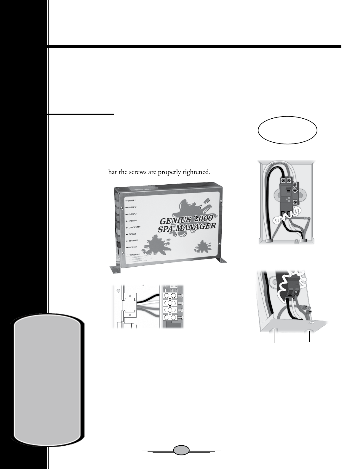
Power Input
All Coyote Spas are tested for the following:
240 VAC, 60 Hz, 50 A
Connect the power input wires to the terminal block
labeled “AC-Input”. Make sure to respect the
alignment and that the screws are properly tightened.
Equipment Compartment and Wiring Diagram
10
10
CAUTION!
Do not turn on power
to the spa until the
spa is filled to the
required level.
Running the spa
pump without water
could cause
immediate damage
and invalidate your
warranty!
IMPORTANT
CONNECTIONS:
Neutral of the GFCI must be
connected to the neutral bus.
Neutral from the spa must
be connected to the breaker.
Sub Panel
Wiring Diagram
Example
From Electrical
Box
To Spa
Load 1
Neutral
Ground
Load 2

Electrical Installation Instructions
11
11
COYOTE SPAS™ MUST BE WIRED IN ACCORDANCE WITH ALL APPLICA-
BLE LOCAL ELECTRICAL CODES. ALL ELECTRICAL WORK SHOULD BE
DONE BY AN EXPERIENCED, LICENSED ELECTRICIAN AND APPROVED
BY A LOCAL BUILDING/ELECTRICAL INSPECTION AUTHORITY. WE
RECOMMEND THE USE OF APPROPRIATE ELECTRICAL CONDUIT, FIT-
TINGS AND WIRE FOR ALL CIRCUITS. The spa can be wired with one 50 amp
240 volt single circuit, one 25 amp circuit or two 25 amp circuits.
We recommend an electrical subpanel containing a 50 amp GFCI breaker is used to supply power
and protect the spa. This subpanel requires a 50 amp, two pole, single phase, 240 volt, four wire ser-
vice (two line, one neutral, one ground). The grounding conductor must be at least the same gauge
as the line conductors, but not less than #6 AWG (Canada), and #8 AWG (USA). A minimum #6
AWG (Canada), and #8 AWG (USA) solid copper bond wire is also required. Mount the subpanel
in the vicinity of the spa, but not closer than five feet away, in accordance with all local codes. The
electrical circuit must be installed by a qualified electrician.
1. This hot tub must be permanently connected (hard-wired) to the power supply. No plug-
in connections or extension cords are to be used in conjunction with the operation of this
hot tub. Supplying power to the hot tub which is not in accordance with these instructions
will void both the independent testing agency listing and the manufacturer’s warranty.
2. The power supplied to this hot tub must be a dedicated circuit with no other appliances or
lights sharing the power provided by the circuit.
3. Do not use aluminum wire.
4. For the United States, the electrical supply for this product must include a suitably rated
switch or circuit breaker to open all ungrounded supply conductors to comply with Section
422-20 of the National Electrical Code, ANSI/NFPA 70. The disconnecting means must be
readily accessible to the hot tub’s occupant but installed at least 1.5m (5 feet) from hot tub
water.
5. The electrical circuit supplied for the hot tub must include a suitable ground fault circuit
interrupter (GFCI) as required by electrical code.
6. To gain access to the hot tub’s power terminal block, remove the four screws securing the two
cabinet panels on the side of the spa containing the ETL label. Then open the door to the
control box.

12
12
7. Install the cable with appropriate connector through the large opening provided in the side
of the control box.
8. Connect wires, color to color, on terminal blocks TB1. TIGHTEN SECURELY! All wires
must be hooked up or damage could result.
9. Close the control box door and reinstall the cabinet side panel.
WARNING: Fill the spa with water before turning on the power.
Once your spa has been filled with water, turn it on and test all of the circuit breakers.
NOTE: If the GFCI breaker trips immediately, verify that the WHITE neutral wire is connected
into the load neutral in the breaker. Each breaker should be tested prior to each use. Here’s how:
1. Push the “TEST” button on each GFCI breaker, and observe it click OFF.
2. Push the breaker switch to the OFF position (to ensure that it has completely disengaged),
then push the breaker switch to the ON position.
If any of the GFCI breakers fails to operate in this manner, your spa may have an electrical malfunc-
tion, and you may be at risk of electrical shock. Turn off all circuits and do not use the spa until the
problem has been corrected by an authorized service agent.
WARNING: Removing or bypassing any GFCI breaker will result in an unsafe spa and will void the
spa’s warranty.
IMPORTANT: Should you ever find the need to move or relocate your Coyote Spas™, it is essential
that you understand and apply these installation requirements. Your Coyote Spas™ has been care-
fully engineered to provide maximum safety against electric shock. Remember, connecting the spa to
an improperly wired circuit will negate many of its safety features.

Startup Procedures
13
13
IMPORTANT:
Your Coyote Spa™ has been thoroughly tested during the manufacturing process
to ensure reliability and long-term customer satisfaction. Before filling the spa,
wipe the spa shell clean with a soft rag.
The following instructions must be read and followed exactly to ensure a successful start-up or refill.
1) Ensure the electrical connections have been made in accordance with this manual.
2) Ensure all O-Rings have been installed into unions and unions have been tightened sufficiently.
3) Ensure all ball valves are open, and the drain has been closed.
4) Fill the spa with water to approximately 4” (10cm) above the top of the filter bucket with a gar-
den hose.
5) Once the spa is filled to the proper level, turn the power to the spa on, by turning on the GFCI
breaker in your panel. Watch the display on the topside control. After power-up, the display
will blink until a key is pressed. This feature is to let you know that the set point and other
system parameters are at their default settings.
6) The jet pump, heating system and all internal plumbing will achieve a partial prime as the spa
is filled. Once the spa is full, turn each pump on to complete prime.. Once the jet system is fully
operational (as indicated by strong, non-surging jets), priming of the spa is complete. Weak or
surging jets are an indication of a low water level condition or clogged filter cartridges.
7) Adjust the chemicals and balance the water according to your dealer’s instructions.
A guideline is also included in this manual, under the Water Maintenance Section.
8) Set the temperature control to the desired temperature (between 38°C and 40°C
or 100ºF and 104ºF), then place the vinyl cover on the spa and allow the water
temperature to stabilize (approximately 16 hours). Make sure you secure the cover
in place using the cover locks. Periodically check the spa water temperature. When
the water temperature climbs above 29°C (84ºF), proceed to the next step.
CAUTION!
Do not turn on power
to the spa until the
spa is filled to the
required level.
Running the spa
pump without water
could cause
immediate damage
and invalidate your
warranty!

9) Test and Adjust Sanitizer level (Chlorine ideal 1 - 3 ppm or Bromine ideal 3 - 5 ppm).
10) The spa temperature is pre-programmed to reach 35°C (95ºF), and will normally do so within
16 to 24 hours. You may raise the water temperature by pressing the TEMP ( ) button on
the control panel, or lower it by pressing TEMP ( ) button. After a few hours, the water
temperature will remain within 1 degree of your selected temperature.
14
14
Venturi Controls
The Venturi Controls allow you to control the intensity of the massage at each jet by adjusting the
mixture of air and water. Simply turn the venturi control lever counter clockwise for a stronger flow
and clockwise for a softer flow.
Diverter Jetting System*
With your Diverter Jetting System, you can control the massaging action of your spa.* On select
models. Using the diverter, the jets are activated in groups, known as jet systems. The jetting systems
are selected by turning the diverter from one side to the other, or select both by leaving the diverter
in the middle. The number of diverters you will have will depend on the model of Coyote Spas™
you have. Feel free to consult your local dealer with any questions regarding the function of this
system, or just jump in and experiment for yourself.

Jets
15
15
Directional Luxury Hydromassage Jets
The Directional Luxury Hydromassage jets allow you to aim the water in the direction that feels
best. These jets are designed to massage the muscles in your upper back, shoulders and neck. These
jets are adjustable by turning the face of the jet clockwise for a stronger flow and counter-clockwise
for a softer flow and eventually off.
Pulsing Luxury Hydromassage Jets
Approximently half of the water jets in each coyote spa are pulsing. These jets provide a pulsing mas-
sage feeling and are all adjustable by turning the face of each jet.
Chrome Jet Option Package
The Chrome jets are made from rust resistant stainless steel; however improper water chemistry may
cause rusting. Same great massage quality in a nicer looking package.
Topside Control Panel
16
16
IMPORTANT. Before performing any service on the spa, contact your local Factory Authorized
Dealer. Make a visual inspection of the spa to get an understanding of what condition it may be in
and if anything looks out of the ordinary. If any part appears to be damaged, loose or missing, do not
proceed. Contact your Factory Authorized Dealer immediately.
Your spa control has been specifically designed so that by simply connecting the spa to its properly
grounded source, and following the start-up procedures in this manual, the spa will automatically
heat to the set temperature. You can adjust the set temperature by pressing the up or down arrows on
your control panel to the desired temperature. When your spa is heating the heat indicator on your
control panel will be on.
102
Power-up Detection
After a power-up, on the first 10 seconds the display will alternate between the software number and
revision, the display will then blink until somebody presses a key. This feature is to let the user know
that a power failure has occurred.
Temperature displayed in Fahrenheit or Celsius
Press and hold the Light Key for 5 seconds to toggle between Fahrenheit and Celsius.
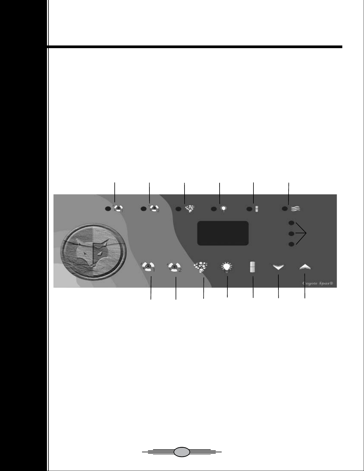
Pump 1
LED
Pump 2
LED
Blower
LED
Light
LED
Filter Cycle
LED
Heater
LED
Pump 1
Button
Pump 2
Button
Blower
Button
Light
Button
Filter Cycle
Button
Down
Button
Up
Button
Error
Message
Lights

17
17
The topside control panel has buttons which you press to set the temperature, initiate the filtra-
tion cycle, turn the light on, and activate or deactivate the pump(s) and blower. The Topside
control panel display responds to let you know you have pressed a button, and that the selected
function has been performed.
Temperature Control (Up & Down Buttons)
These keys are used to set the temperature of the water. As soon as you press one of these keys,
the display will show the current set point and will keep showing it for 5 seconds after releasing
the key. Pressing the keys will either increase or decrease the current set point. The Set Point
LED on the display tells you if the display shows the current set point or the actual tempera-
ture of the water.
The water temperature can be adjusted in 1 degree increments from 15 to 40°C (59ºF to
104ºF). After a power down, the default set point is 39°C (102ºF).
When the water temperature is 0.5ºC lower than the set point, the heater will come on until
the water temperature reaches the set point plus 0.5ºC. The Heater LED on the display will
blink when the system calls for heat and will come on when the heater is actually turned on.
Pump 1 Button
This key is used to turn Pump 1 on in the sequence Low, High, then Off. A built-in
20-minute timer will shut the pump off unless the user does so manually. The pump
LED on the display will be on when the pump is running. When there is a Heat demand, a
Cooldown period (30 seconds after heater turns off), or when pump is running because of a
filter cycle, the controller will turn the pump on Low speed. Then, if the user presses the Pump
key, Pump will go directly into High speed.
Pump 2 Button (Optional)
This key is to turn Pump 2 on in the sequence of High, then Off. A built-in 20-minute
timer will shut off the pump unless the user does so immediately. The LED beside the
the Pump 2 logo on the display will be solid when the pump is running. When there is a filter
cycle (first phase) the controller will turn the Pump 2 on in High speed for one more minute.
Then, if the user presses the Pump 2 key within the first phase of the Filter Cycle, Pump 2 will
turn off.

18
18
Blower Button
This key is used to turn the Blower On/Off. A built-in 20-minute timer will shut
the Blower off unless the user does so manually.
The LED beside the Blower logo on the display will be solid when the Blower is
running. This feature is not available on the Bandit or the Outlaw models.
Light Button
This key is used to turn the Light Switch Off/On. A built-in 2 hour timer will
shut off the light, unless user does so manually.
The LED beside the Light logo will be solid when light is on.
* If the Peyote Light option was installed, repeatedly pushing the light button will
cycle through the different colors.
Filter Button
This key is used to control the Filter cycle. A Filter cycle consists of starting pump
#2 and the blower for 1 minute to purge their plumbing and then start pump one
low speed for the duration of the cycle.
The LED for the Filter logo is solid when there is an active Filter cycle. If the user
presses any key this will suspend the Filter cycle and the LED will flash.
Filter Cycle Duration and Frequency Adjustment
The Filter cycle Duration is user programmable. By pressing the Filter key, the display
shows the current duration value “Fdxx”, where xx is from 0 to 2. Using the Up and
Down keys, this value can be adjusted as desired.
The Filter cycle Frequency (per day) adjustment is user programmable by pressing an-
other time on the Filter key, the display will show the current frequency value (“FFxx”,
where xx is the frequency). Using the Up and Down keys, this value can be adjusted from
1 to 4. If a duration of 0 is selected, the Filter cycle never comes on and the Frequency
selection is not offered.
The Default frequency per day is four times a day and the default number of hours per
cycle is one hour.
During the duration adjustment or the frequency per day adjustment, if the user doesn’t
use any key for 5 seconds, the system “stores” the new duration and new frequency, but
these will take effect only at the next Filter cycle. However, if the user exits the duration
or frequency adjustments by pressing the Filter key again, a new Filter cycle is immedi-
ately started, and a new 12-hour cycle is started.

19
19
Overtemp During Filter Cycle
In order to prevent excessive water temperatures due to long Filter cycles during warm weather, the
system has a special safeguard.
If the water temperature exceeds the set point by more than 2 degrees F, the system will cancel the
Filter cycle and the Filter cycle icon will blink for the remainder of the filter cycle. The Filter cycle
icon blink pattern will be: ON for 1/2 second, OFF for 1/2 second, ON for 1/2 second, and then
finally OFF for a longer 1 1/2 second period. In special circumstances your dealer can disable this
feature.
Overtemp Error
If the water temperature reaches 62ºC (112ºF) on the regulation probe, all pumps and accessories
will be stopped. The Filter cycle and user demand will be cancelled as well. The bottom 2 LED’s to
the right of the temperature display will be flashing. The system will return to normal mode when
the temperature cools to 43ºC (109ºF).
High-Limit
When water at the high-limit sensor reaches 48ºC (119ºF) the bottom 2 LED’s to the right of the
temperature display will be solid, but all of the accessories will still function. The heater will remain
off until a complete shut down of the circuit occurs.
Pressure Switch
When pump #1 is not running, the pressure switch must be open, if not, the top and bottom LED’s
to the right of the temperature display will be flashing.
When pump #1 is on, the pressure switch is given 5 seconds to close. If, after this delay, the switch
is still open, a FLOW error occurs (the top and bottom LED’s to the right of the temperature display
will be solid).
Ozone Output (Optional)
During the Filter cycle, the ozone output is turned on. The filtration cycle can be suspended for
various reasons, in which case ozone out put will be suspended as well.

Spa Care and Maintenance
20
20
Your Coyote Spa™ is manufactured from the highest quality, most durable materials available. Even
so, the spa care and maintenance program you develop will ultimately determine how long your spa
and its individual components will last. Regular maintenance according to the advice in this section
will help you to protect your investment.
Draining the Water
Detergent residues and dissolved solids from bathing suits and chemicals will gradually accumulate in
your spa’s water. Normally, in about three to four months the water will become difficult to balance
and should be replaced. Showering without using soap prior to entering the spa or using only the
rinse cycle when laundering your bathing suit will help to reduce detergent residue in the spa wa-
ter. However, foam problems are more likely to be caused by a build up of organic pollutants in the
spa-mostly by body oils. If you’re using your spa frequently with a high bather load the water will
need to be replaced more often. Spa water gradually loses quality because of build ups of unfilterable
pollutants.
IMPORTANT: Remember to change your water every three to four months.
To Drain Your Spa:
1. Trip the RCD breaker located in the subpanel or the quick disconnect.
2. All Coyote spas have an external drain that can be attached to a typical garden hose for conve-
nient draining. Simply locate the drain on the side of the floor, pull the nozzel out, remove cap, and
attach your hose. Once the hose is attached, push the nozzle in slightly to open the internal valve
and the spa will start draining.
Note: All Coyote Spas™ models will drain almost completely through the drain. Equipment
such as the pump(s) and heater will drain. Any water remaining in the plumbing or equipment
after draining will only need to be removed if the spa is being winterized.
3. When empty, inspect the spa shell and clean as required.
4. Close the drain valve.
5. Refill the spa BEFORE restoring power.
IMPORTANT: Always clean and rotate the filter cartridges, every couple of weeks, and each time
the
spa is drained for cleaning. Or, if using disposable filters change as needed or every 3 months other-
wise.
This manual suits for next models
4
Table of contents
Popular Hot Tub manuals by other brands


American Standard
American Standard Cadet 2770.XXXW Series installation instructions

BullFrog
BullFrog I 331 Series owner's manual

Invacare
Invacare Tub Bar Assemby, installation and operating instructions

Tadpole
Tadpole 2003 Tadpole owner's manual

EDGE THEORY LABS
EDGE THEORY LABS Edge Tub Setup instructions

Bestway
Bestway Lay-Z-Spa 54154 manual


