CP Plus CP-TNW-HP4H1-6 User manual

Feature
1
4 ports PoE Ethernet Switch is a security surveillance Ethernet Switch which aims at Ethernet
high definition surveillance and Ethernet project security system. The product fully combines the
characteristics of security surveillance, provides fast packet forwarding ability and abundant
backplane bandwidth, which ensures clear image and fluent transmission. Inserted static, surge
protection circuit can improve product stability. The product supports one key CCTV model, can
achieve VLAN, QoS priority after configuration, control the Net storm, protect the information
security, prevent the viral transmission and Ethernet attack, fully satisfy the Ethernet video
security surveillance system and Ethernet project needs.
4×10/100Base-TX Ethernet ports (PoE ports) and 1×10/100Base-TX up-link port;
Support IEEE802.3af/at standards,Max.30W output of single port;
One-key CCTV mode: 1~4 downlink ports can only communicate with uplink ports,extend
transmission distance up to 250m(10Mbps);
6KV surge protection, 8KV ESD immunity and anti-interference;
Easy & safe installation: wall-mounting, desktop,Kensington security slot;
Plug-and-play.
Application
Notice
The transmission distance depends on the signal source and cable quality; standard Cat5e/6
Ethernet cable is strongly suggested for reaching the maximum transmission distance! Every
100 mtr each power port drop will be approx 3 to 5 watts. After 250 mtr available POE power
will be approx. 15W to 20W at each IPC side.
4 Ports PoE Ethernet Switch
Cat5/5e/6 network cable
LCD
NVR
PoE PTZ Camera
PoE IP Camera
PoE Dome Camera
PoE IP Camera
power
4 Por t PoE Switch
Model: CP-TNW-HP4H1-6
※

Please follow the below installation steps
Please check the following items before installation, if it is missing, please contact the dealer .
4 ports PoE Ethernet Switch 1pc
1pc
1pc
Power adaptor
AC power cable
User manual 1set
1) Please turn off the signal power and display device power before installation, installation
with power will damage the transmission equipment;
2) Use network cable connect PoE IP camera and 1~4 down link ports of product respectively;
3) Use a network cable connect equipment up link port and NVR or computer;
4) Turn on the power of the equipment;
5) Check if the installation is correct, equipment is in good condition, the connection is stable,
then provide power for system;
6) Ensure the Ethernet equipment with power and work properly.
Installation ste
ps
4 Port PoE Switch
2
Board Diagram
Front board
Kensington Lock
Back board
Side board
1)
2
The equipment must connect the ground according to the request.
Turn the dial switch for left, the equipment can enter CCTV mode after restart the
equipment power.
)
Description:
CCTV mode
PoE down link
Ethernet port
Uplink
Ethernet port Ground
Power
input port
Power
indicated light

4 Port PoE Switch
3
连接接口
Specification
Item
Description
Power
Power Supply
Power Adaptor
Voltage Range
DC48V~54V
Consumption
<5W
Ethernet
Speed
1 4 port Default:10 100Mbps
CCTV:10Mbps;
Uplink port 100Mbps
- : / ;
:
Transmission Distance
1 4 port:Default 0 100m;
CCTV:0~250m;
UPLINK:100m
- : ~
※
Network Switch
Ethenet Standard
IEEE 802 3 802 3u/802.3af/at . / .
Exchange Capacity
1.0Gbps
Packet Forwarding Rate
0.74Mpps
Packet Buffer
768K
MAC Address
2K
Status Indicator
Power Light
1pc(Red)
Ethernet Port Light
2pcs(Yellow&Green) on RJ45 yellow indicates PoE,
green indicates Link Act
,
/
Surveillance Module Light
1pc(Green), green indicates CCTV
Protection Level
Pluse Group
Level 3
Standard: IEC61000 4 4
- -
ESD
Contact Discharge 6KV
Air Discharge Level 8KV
Standard: IEC61000-4-2
Anti thunder Level-
Common mode 6KV
Standard: IEC61000 4 5
- -
Working
Environment
Working Temperature
- ℃10 ~55℃
Storage Temperature
- ~ ℃40 85℃
Humidity Non condesing( - )
0 95~ %
Mechanical
Dimension L W H( * * )
135mm 85 6mm 27mm× . ×
Out Shell
Galvanized Sheet
Color
Gray
Weight
315g
4 Port PoE Switch
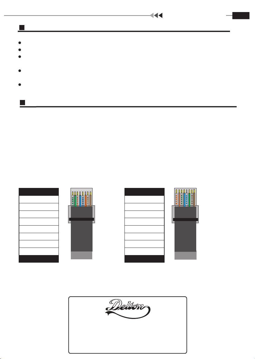
Instruments to be used: wire crimper, network tester. Wire sequence of RJ45 plug should
conform with EIA/TIA568A or 568B.
1) Please remove 2cm long the insulating layer, and bare 4 pairs UTP cable;
2) Separate the 4 pairs UTP cable and straighten them;
3) Line up the 8 pieces of cables per EIA/TIA 568A or 568B;
4) Cut off the cables to leave 1.5cm bare wire;
5) Plug 8 cables into RJ45 plug, make sure each cable is in each pin;
6) Use the wire crimper to crimp it;
7) Repeat above 5 steps to make the another end;
8) Use network tester to test the cable if it works.
Plug Producing Method
Pin Color
1
White/Green
2
Green
Blue
3 White/Orange
White/Blue
7 White/Brown
6
Orange
8
Brown
4
5
Pin Color
6
8
3 White/Green
Green
4
Blue
1
White/Orange
5
White/Blue
7
White/Brown
2
Orange
Brown
EIA/TIA 568A EIA/TIA 568B
Trouble Shooting
Please follow the steps if the equipment has trouble.
Make sure the equipment is installed according to the manufactures installation guide.
Confirm RJ45 cable order meets EIA/TIA568A or 568B standard.
Every PoE port can provide PoE equipment maximum power less than 30W, please do not
connect the PoE equipment with power over 30W.
Replace the equipment with a proper functioning
equipment is damaged.
Please contact your vendor if trouble still exists.
4 ports PoE Ethernet Switch to check if the
1095 Budapest, Mester utca 34.
Tel.: *218-5542, 215-9771, 215-7550,
216-7017, 216-7018 Fax: 218-5542
Mobil: 30 940-1970, 20 949-2688
www.cpplus.hu
1141 Budapest, Fogarasi út 77.
Tel.: *220-7940, 220-7814, 220-7959,
220-8881, 364-3428 Fax: 220-7940
Mobil: 30 531-5454, 30 959-0930
Other CP Plus Switch manuals


