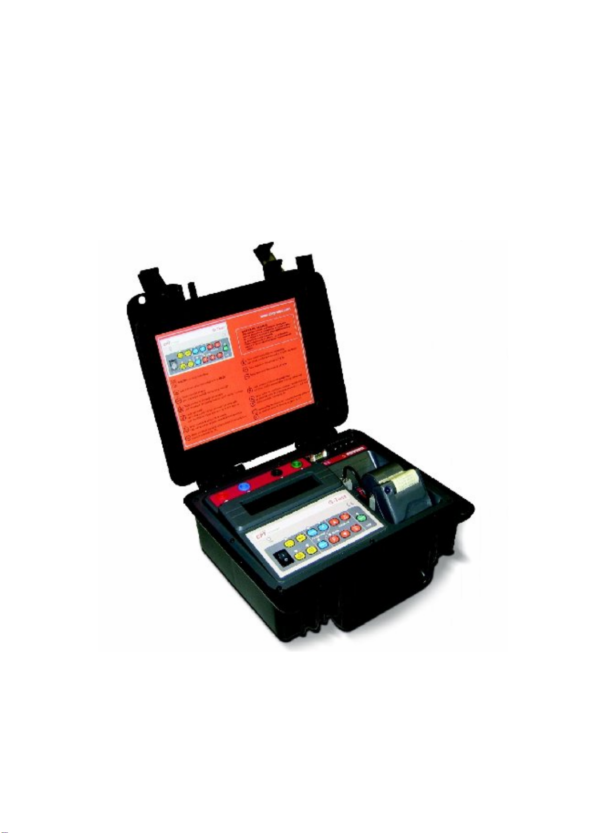
CPT G-TEST User manual

G-TEST
接地電阻測試器
使用手冊

33
G-TEST
Microprocessor Controlled Digital Earth Tester
User’s Guide

34
Index
1. Description_______________________________________________________ 35
1.1. Control panel _________________________________________________ 36
1.1.1. Connections and items ______________________________________ 36
1.1.2. Keyboard _________________________________________________ 37
1.1.3. LED's ____________________________________________________ 38
1.2. Measurement ranges ___________________________________________ 38
2. Battery / battery charger ____________________________________________ 39
3. Real time clock and calendar_________________________________________ 40
4. Equipment calibration checking_______________________________________ 40
5. Grounding resistance measurement ___________________________________ 41
5.1. Observations about grounding diffusion systems (GDS) ________________ 42
6. Spurious voltages measurement ______________________________________ 43
7. Soil resistivity measurement _________________________________________ 44
8. Abnormalities indications on the display ________________________________ 46
8.1. Excessively high spurious voltages ________________________________ 46
8.2. Excessively high earth resistance__________________________________ 46
8.3. Excessively high resistance in the auxiliary rods ______________________ 46
8.4. Excessively high soil resistivity____________________________________ 47
9. Exporting data to the computer _______________________________________ 47
10. Printer _________________________________________________________ 48
11. Technical Specifications ___________________________________________ 49

35
1. Description
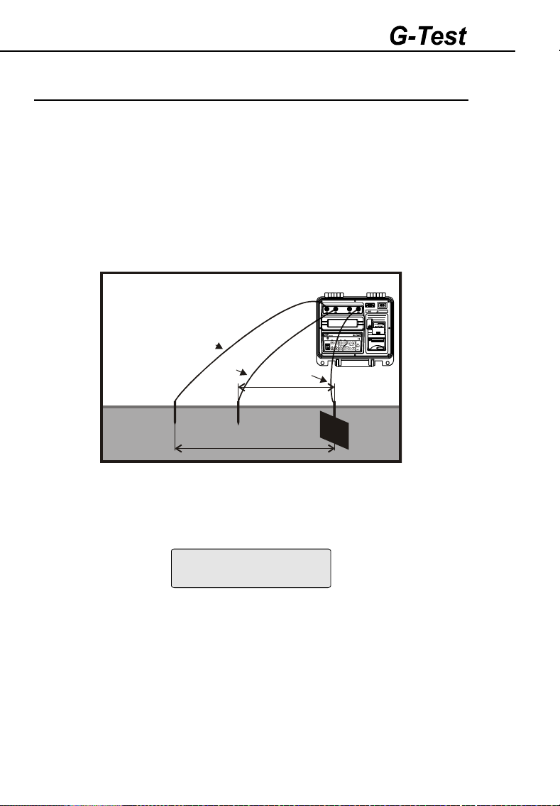
The G-TEST is a microprocessor controlled earth tester that allows meas-
uring earth resistance and ground resistivity (by Wenner's method), as well
as detecting parasitic voltages that may be present in the ground. Totally
automatic and easy to operate, the G-TEST is suitable to measure earth
systems in power substations, industries, distribution networks, etc., ac-
cording to IEC 61557-5, or to measure soil resistivity in a terrain, in order to
optimize the earth systems project.
Before starting each test, the G-TEST will check if all conditions are within
the appropriate limits and will notify the operator if there are any abnormali-
ties, such as too high interference voltage, too much resistance in the test
spikes, very low test current, etc. If all conditions are normal, the equipment
will automatically select the adequate range and will show the results on the
display.
In order to conveniently test earth systems, the G-TEST allows measure-
ments using test currents with selectable frequency, of 270Hz or 1470Hz.
Measurements in the 270Hz frequency allow to analyse the system behav-
iour when in contact with fault currents of industrial frequency, while those in
the 1470Hz frequency show better the system behaviour when in contact
with electrical currents caused by lightning. Measurements in the higher
frequency also offer high immunity to interference voltages in the soil, what
allows accurate results in often unfavorable conditions.
The G-TEST has memory to store up to 4000 measurements, a built-in
printer and a serial data output that allows to transfer the stored results to a
computer or data logger for later analysis. Practical, lightweight and strong,
the G-TEST is suitable to field use, even under severe weather conditions.
It is powered by a rechargeable battery (220 - 240V charger), and is sup-
plied with all the necessary accessories in a practical auxiliary case.

36
1.1. Control panel
All of the G-TEST buttons, keys, outputs and connections are located on the
panel, and are easily accessible by the operator. The following graphics
show the function of each one of the equipment's items.
1.1.1. Connections and items
!
#
"
$
%
&
'
(
)
HS ES
E
!- Output terminal E
"- Output terminal ES
#- Output terminal S
$- Output terminal H
%- Alphanumeric display
&- Keyboard
'- RS-232 communication port
(- Power supply input
)- Paper feed control

37
1.1.2. Keyboard
*
+
,
-
/
0
1
2
.
3
5
4
6
7
*- ON/OFF switch
+- The printer is active
,- Activates the voltmeter
-- Selects 270Hz frequency
.- Selects the resistivity measurement function
/- Shows the battery charge status on the display
0- Sends stored memory data to a connected computer or data logger
1- Selects 1470Hz frequency
2- Selects the resistance measurement function
3and 4- Increase or decrease the specified distance between rods in a
progression of 1, 2, 4, 8, 16 or 32 meters. It also allows the operator to
select the Rx function, used to check the equipment calibration by using a
standard resistance (ignoring the “distance” parameter, not needed in this
function)
5and 6- Increase or decrease the specified distance between rods in one
meter steps.
7- START key; starts the test.

38
1.1.3. LED's
8
9
:
;
=
<
>
8- The resistance measurement function is selected.
9- The battery charger is operating.
:- The G-TEST is on.
;- The printer is operating.
<- The voltmeter is selected.
=- The resistivity measurement function is selected.
>- A measurement is running.
1.2. Measurement ranges
The G-TEST automatically selects an adequate range when operating,
allowing measurements between 0,01Ωand 20kΩ(resistance), 0,01Ωm
and 50kΩm (resistivity), or voltages between 0 and 60V (when in the volt-
meter function).

39
2. Battery / battery charger
The G-TEST uses a 12V – 2.3Ah rechargeable battery. At the end of its
useful life, the battery must be recycled or disposed of properly, in order to
protect the environment.
Before starting each test, it is recommended to check if the battery has
enough charge. This can be done by pressing the battery status (/) key.
If the battery charge is low, the following message will appear on the dis-
play:
LOW BATTERY
[$ ]
When connected to the power supply, the battery charger will be always
active, even if the G-TEST is off.
Recharge procedure:
Check if the G-TEST is off, and then connect it to the power supply. The
battery charger LED will turn red, and will remain so until the battery is to-
tally recharged. Then, the light will turn to green, and will stay on until the
equipment is disconnected from the power supply.
If the equipment is turned on during the recharge procedure, the display will
show:
Charging
Battery...
During the process, the START7key will be deactivated.
Note: battery slowly loses part of its charge while stored, even whithout
use. Therefore, before using the equipment for the first time, or after a long
period out of use, it may be necessary to recharge the battery.

40
3. Real time clock and calendar
In order to provide an easier identification of each test, the G-Test has a
built-in real-time clock/calendar. Date and time must be adjusted with a PC
software (available at www.cirprotec.com) that sychronizes the equipment
with the PC clock.
4. Equipment calibration checking
By using a standard resistance (Rx), it is possible to test the equipment
calibration. The resistance must be connected to the G-TEST as shown
below:
RX
HS
ES
E
After connecting the resistance, follow these procedures:
•Turn the G-TEST on.
•Select the resistivity function (.).
•In the distance/standard resistance selection function, choose Rx (nomi-
nal standard resistance)
•Press the START7key.
•After 5 seconds, a stable value close to the standard resistance's nominal
value should appear on the display.
•If this is not the case, the equipment accuracy is out of its specification
and must be adjusted by a qualified laboratory.

41
5. Grounding resistance measurement
When turning on the G-TEST, the display will show the opening message,
followed by the parameters Earth Resistance / 3-Pole / 270Hz. These are
the standard functions and frequency; to operate in the 1470Hz frequency,
press the 1470Hz1key.
Insert the auxiliary rods (current rod E3 and voltage rod E2) in the ground.
Using the cables supplied with the equipment, connect the rods to the H$
and S#output terminals, respectively. The grounding system under test
must be connected to E!with the 5 meter cable.
E3 E2
E1
fig. 01
D1
D2
40m cable
20m cable
5m cable
Current
rod Voltage
rod Ground
to be
measured
H
S
ES
E
Press the START7key to start the test. The test number will be shown on
the display, followed by the message “WAIT...”, and after a few moments
the resistance value will appear, as in the following example:
R= 10.01@
3_Pole 270Hz
The result will then be stored on the memory.

42
5.1. Observations about grounding diffusion sys-
tems (GDS)
In order to obtain a valid result when measuring a grounding diffusion sys-
tem (GDS), some additional prerequisites must be observed: the current
electrode must be away enough from the GDS to prevent their influence
areas from overlapping, while the voltage rod (probe) must be set up in the
potential plateau area. Usually, the radius of each influence area is about
three to five times bigger than the electrode's dimensions.
The appropriate compliance of this condition must be checked by carrying
out three successive measurements of the GDS resistance, keeping the
current rod in position, but moving the voltage rod about 2 meters between
measurements (L, M, and Npoints in the image below). If all three meas-
urements show the same result (within the earth meter specified error mar-
gins), the measurement should be considered correct. Otherwise, the dis-
tance from the current rod to the GDS should be significantly increased and
the process, repeated.
Potential plateau
R
A
L
M
N
B
Voltage Rod E2
measurements
points
Current Rod E3
influence area
Ground
diffusion
resistance
Current
Rod E3
Ground diffusion
resistance influence
area

43
Generally, GDS dimensions are greater than those of the auxiliary current
rod, thus its area of influence diameter is also greater. So, in order to com-
ply with the required condition, the probe must be set up closer to the cur-
rent rod than to the GDS. A distance of 62% is usually adopted as a first try.
It should be noted that when measuring GDS resistance in large systems
(such as a large grid that underlies a substation) distances of hundreds of
meters are required to fulfil the condition. Technical literature describes
alternative methods that make it possible to reduce those distances with
valid results.
Note: all these observations refer to physical aspects essential to the measurement
process, being applied to all earth meters, regardless of manufacturer or technology.
6. Spurious voltages measurement
In order to check the existance and measure eventual parasitic currents in
the soil, the rods must be set up in the same position used to perform
grounding diffusion measurements.
After placing the rods, press the voltmeter,key. The display will show the
voltage between the system and the voltage rod, up to a maximum of 60V.
Earth Voltage
V = 1.3 V

44
7. Soil resistivity measurement
Note: in this function, the equipment operates only with the 270Hz frequency.
To select the resistivity measurement function, press the ρ(.) key. Insert
four rods in the ground, well aligned and with an equal distance from each
other. Connect them to the output terminals using the supplied cables. Re-
member that the distance between rods is very important when measuring
soil resistivity, since this value is part of the calculation. Specify the distance
between rods (“a” in the image below and on the display) by using the 3
and 4keys (5and 6to increase or decrease only one meter at a time).
fig. 02
a
H
S
ES
E
a
a
H
S
ES
E
Press the START7key. The G-TEST will automatically apply Wenner's
equation (below) based on collected data.
=
4 Ra
a+ 4 p
2 2
a
1 +
-
a+ p
2 2
Legend:
ρ= soil resistivity value; will be shown on the display
a= distance (in meters) between rods; specified by the operator
p= insertion depth (in meters) of the rods – the G-TEST uses 0,5m
R= resistance value used by the equipment to calculate ρ

45
The display will then show the soil resistivity value, as in the example below:
# = 620 @m
4_Pole a= 2m
To properly evaluate soil resistivity, measurements must cover the whole
area to be influenced by the grounding system. For an area of up to
10.000m², it is recommended to perform measurements in at least five
points, arranged as shown in the image below. Two sets of measurements
should be needed for the central point.
a
ba/4 D
a/2
b/2
b/4
a/4
B
E
A
b/4
C
Measurements points: A, B, C, D & E
Direction of measurements: x & y
yx
Larger areas can be divided in areas of 10,000m² each. In the case of dif-
ferent forms, limiting the area in smaller rectangles is a possible and practi-
cal solution.

46
8. Abnormalities indications on the display
If the G-TEST identifies any abnormality causing the measurements to be
excessively inaccurate, or not possible at all, a warning message will be
shown on the display, allowing the operator to identify and correct the
problem.
8.1. Excessively high spurious voltages
If parasitic currents present in the soil are seriously affecting the equipment
precision, the display will show the following message:
Earth Voltage
too high!
8.2. Excessively high earth resistance
If the system's resistance is exceptionally high (above 20,00 kΩ), and
therefore beyond the equipment range, the following message will appear
(upper line):
R> 20.00k@
3_Pole 270Hz
8.3. Excessively high resistance in the auxiliary rods
If, by any reason, there is no current between H$and E!, or if resistance
on the Hpole is too high, the display will show:
Check H_pole
The reason may be a wrong connection or excessive high-diffusion resis-
tance on the Hpole. Check the installation to correct the problem.
If resistance on the Spole is too high or if there is a disconnection near the
pole, the display will show:
Check S_pole

47
Either resistance diffusion on the Spole may be excessively high, or there
is a disconnection nearby. Check the installation to correct the problem.
In both cases, if the problem is being caused by excessive resistance, wa-
tering the rods or inserting several interconnected rods may reduce the
resistance, allowing measurements to take place correctly.
8.4. Excessively high soil resistivity
If soil resistivity is excessively high (above 50kΩm), and therefore beyond
the equipment range, the following message will appear (upper line):
# > 50k@m
4_Pole a= 3m
9. Exporting data to the computer
To transfer data from the G-TEST memory to a computer, use the commu-
nications cable supplied with the accessories to connect the equipment and
the computer's RS-232 ports.
At Windows START menu, select “Programs”, “Accessories”, “Communica-
tion” and start the “Hyper Terminal”. To create a new connection, choose a
name and an icon, and click “OK”. On the next window, select the correct
COM port. After clicking “OK” again, fill in the following data in that exact
order: 4800, 8, None, 1, None.
The computer is now correctly configured to receive data from the equip-
ment. Press the MEM key and the G-TEST will send all stored data to the
computer, while the display shows the following message:
Sending Data
Wait ...
Memory data will then be available to visualization and archiving in the
computer.

48
10. Printer
Pressing the printer(+) key will print the results and parameters of the last
test. Use the )key to remove the paper before cutting it.
Attention: don't pull the paper manually or try to put it back, or the printer may be
easily damaged.
White side
Yellow side
This printer uses 37mm-wide thermal paper, which comes in a
33mm-diammeter reel. The figure shown below indicates how
to insert paper. Press key ), (until the paper appears). To
remove the old paper reel, cut the paper next to it and press
key ). The removal used-reel operation must be carried out in
this way due to the fact that the paper movement is in one-way
only, that is, the paper can be moved in only one direction.

49
11. Technical Specifications
Application :Earth resistance measuring of simple or complex
electrode systems, Ground resistivity measure-
ments (Four terminal Wenner´s principle), and
Spurious voltage according to IEC 61557-5
Resistance measurement
method
:The equipment injects an electronically generated
current in the soil, and measures, with high preci-
sion, both that current and the voltage developed
in the soil by means of that current flowing through
grounding diffusion resistance. The display shows
the Resistance value.
Operation frequency :During R measurement operators should select the
following test frequencies: 270 Hz ± 1 Hz or 1470
Hz ± 1 Hz
Resistivity measurement
method
:The equipment injects the current in the soil though
the external rods, and measures, with high preci-
sion, both that current and the voltage developed
in the soil. The operator should inform the distance
between spikes and the equipment automatically
compute soil resistivity. The display shows resis-
tivity value, computed with Wenner full equation.
Voltmeter :In the voltmeter function, the equipment operates
as a CA conventional voltmeter, making it possible
to measure voltages generated by parasitic cur-
rents.
Measurement ranges :Resistance: 0 - 20 kΩ(autoranging)
Resistivity: 0 - 50 kΩm (autoranging)
Voltage: 0 - 60 V∼
Accuracy :Resistance and Resistivity measure
ments: ± (2% of
the measured value ± 2 digits)
Voltage measurement: ± (3% of the measured
value ±2 digits)
Reading resolution :0.01 Ωin the resistance measurement.
0.01 Ωm in the resistivity measurement.
0.1 V in the voltage measurement.
Output current :The short-circuit current is limited to less than
3.5mA r.m.s. (according the IEC 61557-5 - 4.5 )
Immunity to spurious voltage
interference
:During the R measurement, it allows for the pres-
ence of spurious voltage up to 7 V~

50
Earth resistance of auxiliary
rods :In the R measurement it allows Raux up to 50 kΩ
with error < 30%
Battery status checking :The battery charge status is verified under normal
using conditions.
Advanced Features :Automated detection of abnormal conditions that
may cause excessive errors (low battery, too high
noise interference, too high test spikes resistance)
Soil Resistivity Computing :When performing soil resistivity measurements, the
operator informs to the G-TEST the distance be-
tween spikes and the equipment automatically
computes soil resistivity using the Wenner full
equation.
Serial Data Output :RS-232 @ 4800 bps. Suitable for data collection in
an external serial printer, computer or data-logger.
Built-in printer :For a printed register document of measured val-
ues.
Power supply :By means of an internal rechargeable battery, 12
V
2.3 Ah.
Battery charger :A smart, microprocessor-controlled, circuit that
adjusts the battery charge to the optimised pa-
rameters in order to ensure highest service life.
Power supply: 220-240 V∼50 Hz
Safety Class :It meets the requirements of IEC 61010-1/1990,
IEC 61010, 1/1992 amendment 2
E.M.C :In accordance with IEC 61326-1
Electrostatic immunity :In accordance with IEC 1000-4-2
Electro magnetic irradiation
immunity
:In accordance with IEC 61000-4-3
Environmental Protection :IP-54 with closed lid.
Altitude Maximum :3000m
Operation temperature :-10°C to 50°C
Storage temperature :-25°C to 65°C
Humidity :95% RH (without condensation)
Equipment weight :Approximately 3.0kg (without accessories)

51
Size :274 x 250 x 124 mm
Included Accessories :•Four steel rods.
•Power supply cable.
•RS-232 cable.
•One 40 meters cable in red colour.
•Two 20 meters cable in blue and green colour.
•One 5 meters cable in black colour.
•One 5 meters cable to connect to the grounding
system to be measured.
•Canvas bag.
•This User’s guide.
MARK
Technical modifications reserved.
Table of contents
Popular Test Equipment manuals by other brands

Tektronix
Tektronix TOP 130 user manual

HV Diagnostics
HV Diagnostics HVA 34 user manual

Velleman
Velleman HQ Power HQLE10026 user manual

Berkeley Varitronics Systems
Berkeley Varitronics Systems Mantis user manual

EiE INSTRUMENTS
EiE INSTRUMENTS EIE-402DP product manual

Dräger
Dräger Quaestor 6000 Instructions for use