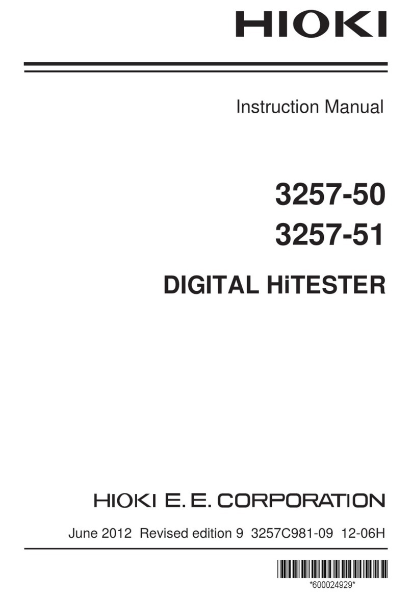
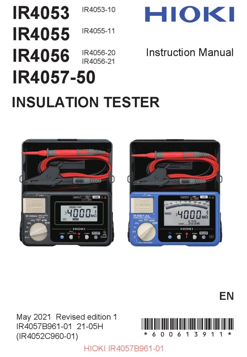
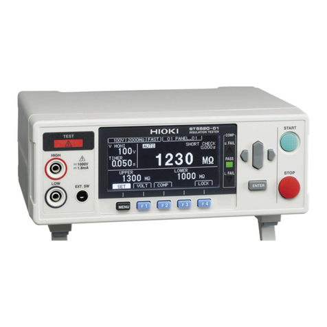
Hioki 3455 User manual

3455
HIGH VOLTAGE
INSULATION HiTESTER
Instruction Manual
February 2013 Revised edition 10 3455A981-10 13-02H


1
2
3
4
5
6
7
8
9
10
11
付録
索引
i
Contents
Introduction ......................................................1
Verifying Package Contents / Open the case ..1
Safety Information ...........................................5
Operating Precautions .....................................8
1 Overview 13
1.1 Product Overview .................................13
1.2 Features ...............................................15
1.3 Measurement Overview .......................17
1.4 Names and Functions of Parts .............24
1.5 Screen Setup .......................................28
2 Measurement Preparations 31
2.1 Supplying Power ..................................31
2.1.1 Installing or Replacing the Battery ......31
2.1.2 Installing the Battery Pack
(Rechargeable nickel-hydrogen battery) .......34
2.1.3 Connecting the AC Adapter ................39
2.1.4 Charging the Battery Pack .................41
2.2 Turning Power On and Off ...................44
2.2.1 Auto Power Off ...................................45
2.3 Setting and Checking Date and Time ..46
2.3.1 Setting Date and Time ........................46
2.3.2 Checking Date and Time ....................49
2.4 Connecting Test Lead ..........................50
2.5 Connecting Temperature Sensor .........52
3 Measurement 53
3.1 Pre-Operation Inspection .....................53
3.2 Measuring Insulation Resistance .........56

ii
3.2.1 Starting Measurement .........................58
3.2.2 Ending Measurement ..........................64
3.2.3 Checking and Deleting Held Data .......66
3.2.4 Automatic Discharge Function ............67
3.2.5 Switching to Leakage Current
Indication .............................................68
3.2.6 Insulation Resistance Measurement
Basis ...................................................69
3.2.7 Use of GUARD Terminal .....................71
3.3 Measuring Voltage ...............................73
3.4 Measuring Temperature .......................76
3.4.1 Measurement Procedure ....................76
4 Advanced Measurement 79
4.1 Using Timer ..........................................79
4.1.1 Setting Timer/Conducting Insulation
Resistance Measurement ...................79
4.2 Displaying PI and DAR .........................83
4.3 Temperature Correction (TC) ...............87
4.3.1 Performing Temperature Correction ...88
4.3.2 Exiting Temperature Correction Mode 92
4.4 Step Voltage Test .................................93
4.4.1 Setting and Conducting a Step
Voltage Test ........................................94
4.4.2 Viewing Detailed Data of Each Step
after Step Voltage Test .......................97
4.4.3 Exiting Step Voltage Test Mode ..........99
5 Recording Measurement Data
(Memory Function) 101
5.1 Recording Measurement Data ...........103
5.1.1 Manual Recording (Recording result
of one measurement session) ...........103
5.1.2 Logging Recording
(Recording at regular intervals) .........106
1
2
3
4
5
6
7
8
9
10
11
付録
索引
iii
5.2 Checking Recorded Data ...................115
5.3 Deleting Recorded Data .....................120
5.3.1 Deleting Data of Chosen No. ............120
5.3.2 Deleting all Data ...............................121
6 Other Functions 123
6.1 Changing and Checking Interval
Setting for PI Calculation ...................123
6.1.1 Changing Interval Setting .................123
6.1.2 Checking Interval Setting .................125
6.2 ChangingandCheckingVoltageApplication
Time for Step Voltage Test ....................126
6.2.1 Changing Time Setting .....................126
6.2.2 Checking Time Setting .....................128
6.3 Entering Temperature and Humidity
Measured with External Thermometer
and Hygrometer .................................129
6.3.1 Entering and Saving .........................130
6.3.2 Clearing Indications of Temperature
and Humidity Stored Data ................133
6.4 Communicating with PC .....................134
6.4.1 Installing Data Analysis Software
for 3455 ............................................135
6.4.2 Installing Driver .................................136
6.4.3 Downloading Data to Save to PC/
Setting up Tester on PC ...................137
7 Specifications 139
7.1 General Specifications .......................139
7.2 Measurement Specifications ..............144
7.2.1 Insulation Resistance Measurement 144
7.2.2 Leakage Current Measurement ........147
7.2.3 Voltage Measurement ......................148
7.2.4 Temperature Measurement ..............149

iv
7.3 9750-01, -02,- 03, -11, -12, -13
TEST LEADs and 9751-01, -02, -03
ALLIGATOR CLIPs Specifications .....150
8 Maintenance and Service 151
8.1 Troubleshooting .................................152
8.2 Cleaning .............................................154
8.3 Error Display ......................................154
8.4 Performing System Reset ..................156
8.5 Discarding the Instrument ..................157
Appendix 161
Appendix 1Test Voltage Characteristic
Graph .................................................161
Appendix 2Example of Insulation Resistance
Criteria ................................................162
Appendix 3Example of PI Criteria
(Polarization Index) ............................162
Appendix 4Temperature Correction Table ...163

Introduction
1
2
3
4
5
6
7
8
9
10
11
付録
索引
1
Introduction
Thank you for purchasing the HIOKI Model
3455 HIGH VOLTAGE INSULATION HiT-
ESTER. To obtain maximum performance
from the instrument, please read this man-
ual first, and keep it handy for future refer-
ence.
• Windows and Internet Explorer are regis-
tered trademark of Microsoft Corporation in
the United States and/or other countries.
• Adobe and Reader are either registered
trademarks or trademarks of Adobe Sys-
tems Incorporated in the United States and/
or other countries.
Verifying Package Contents / Open
the case
When you receive the instrument, inspect it
carefully to ensure that no damage
occurred during shipping. In particular,
check the accessories, panel switches, and
connectors. If damage is evident, or if it fails
to operate according to the specifications,
contact your dealer or Hioki representative.
Open the case by releasing the two latches.
(See next page.)
Registered trade mark
Open the case
Appearance of Case
Cover
Latches
Handle

Verifying Package Contents / Open the case
2
Procedure
1. Draw the latch outwards with your fin-
ger.
2. While raising the entire latch, place a
finger on the top of the latch and pull
it out.

Verifying Package Contents / Open the case
1
2
3
4
5
6
7
8
9
10
11
付録
索引
3
Main Unit
Accessories
3455 HIGH VOLTAGE INSULATION HiTESTER 1
9750-01,-02,-03 TEST LEAD (Red, Black, Blue)
Lead length Approx. 3 m 1 each
LR6 alkaline battery 6Instruction Manual
(This book) 1
USB Cable 1
9751-01,-02,-03 ALLIGATOR CLIP(Red, Black, Blue)
1 each
CD-R (Data Analysis
Software for 3455) 1

Verifying Package Contents / Open the case
4
Options
9750-11,-12,-13 TEST LEAD
(Red, Black, Blue Lead length Approx. 10 m)
The specifications for the 9750-11 and
9750-12 models differ from the standard
specifications in regards to temperature
characteristics.
See 7.2"Measurement Specifications" (page
144).
9631-01,-05 TEMPERATURE SENSOR
Used for temperature measurement.
9631-01: Lead length Approx. 1 m
9631-05: Lead length Approx. 6 cm
9459 BATTERY PACK
(Rechargeable nickel-hydrogen battery)
The 9753 AC ADAPTER is required for
charging.
9753 AC ADAPTER
Input : 100 to 240 VAC
Output: 12 VDC 3.33 A

Safety Information
1
2
3
4
5
6
7
8
9
10
11
付録
索引
5
Safety Information
Safety Symbols
This manual contains information and warn-
ings essential for safe operation of the
instrument and for maintaining it in safe
operating condition. Before using it, be sure
to carefully read the following safety pre-
cautions.
This instruments designed to comply
with IEC 61010 Safety Standards, and has
been thoroughly tested for safety prior to
shipment. However, mishandling during
use could result in injury or death, as well
as damage to the instrument. However,
using the instrument in a way not
described in this manual may negate the
provided safety features. Be certain that
you understand the instructions and pre-
cautions in the manual before use. We
disclaim any responsibility for accidents
or injuries not resulting directly from
instrument defects.
In the manual, the symbol indicates particularly impor-
tant information that the user should read before using the
instrument.
The symbol printed on the instrument indicates that the
user should refer to a corresponding topic in the manual
(marked with the symbol) before using the relevant func-
tion.
Indicates that dangerous voltagemay be present at this ter-
minal.
Indicates a double-insulated device.
Indicates DC (Direct Current).
Indicates AC (Alternating Current).

Safety Information
6
The following symbols in this manual indi-
cate the relative importance of cautions and
warnings.
Other Symbols
Accuracy We define measurement tolerances in
terms of rdg. (reading) and dgt. (digit) val-
ues, with the following meanings:
Indicates that incorrect operation presents an extreme
hazardthatcouldresultin seriousinjuryordeathtothe
user.
Indicatesthatincorrectoperationpresentsasignificant
hazardthatcouldresultin seriousinjuryordeathtothe
user.
Indicatesthatincorrectoperationpresentsapossibility
of injury to the user or damage to the instrument.
Indicates advisory items related to performance or cor-
rect operation of the instrument.
Indicates a prohibited action.
Indicates the location of reference information.
Indicates quick references for operation and
remedies for troubleshooting.
*Indicates that descriptive information is provided
below.
dgt.
(resolution) The smallest displayable unit on a digital measur-
ing instrument, i.e., the input value that causes
the digital display to show a "1" as the least-sig-
nificant digit.
rdg. (reading
or displayed
value) The value currently being measured and indicat-
ed on the measuring instrument.

Safety Information
1
2
3
4
5
6
7
8
9
10
11
付録
索引
7
Measurement categories
This instrument and 9750-01, -02, -03, -11,
-12, -13 TEST LEAD comply with CAT IV
(600 V), CAT III (1000 V) safety requirements.
To ensure safe operation of measurement
instruments, IEC 61010 establishes safety
standards for various electrical
environments, categorized as CAT II to CAT
IV, and called measurement categories.
These are defined as follows.
Using a measurement instrument in an
environment designated with a higher-num-
bered category than that for which the
instrument is rated could result in a severe
accident, and must be carefully avoided.
Use of a measurement instrument that is
not CAT-rated in CAT II to CAT IV measure-
ment applications could result in a severe
accident, and must be carefully avoided.
CAT II Primary electrical circuits in equipment connected to an
AC electrical outlet by a power cord (portable tools,
household appliances, etc.) CAT II covers directly mea-
suring electrical outlet receptacles.
CAT III Primary electrical circuits of heavy equipment (fixed in-
stallations) connected directly to the distribution panel,
and feeders from the distribution panel to outlets.
CAT IV The circuit from the service drop to the service entrance,
and to the power meter and primary overcurrent protec-
tion device (distribution panel).

Operating Precautions
8
Operating Precautions
Follow these precautions to ensure safe
operation and to obtain the full benefits of
the various functions.
Before using the instrument the first time,
verify that it operates normally to ensure
that the no damage occurred during stor-
age or shipping. If you find any damage,
contact your dealer or Hioki representative.
Preliminary Checks
Before using the instrument, make sure
that the insulation on the test leads and
cables is undamaged and that no bare
conductors are improperly exposed.
Using the product in such conditions
could cause an electric shock, so contact
your dealer or Hioki representative for
replacements.
(Model 9750-01,-02,-03 TEST LEAD,
Model 9751-01,-02,-03 ALLIGATOR CLIP)
To prevent an electric shock accident, con-
firm that the white or red portion (insulation
layer) inside the cable is not exposed. If a
color inside the cable is exposed, do not use
the cable.

Operating Precautions
1
2
3
4
5
6
7
8
9
10
11
付録
索引
9
• Operating temperature and humidity:
0 to 40°C (32 to 104
°F
)
90%RH or less (no condensation)
• Temperature and humidity range for guaran-
teed accuracy:
Insulation resistance measurement / leak-
age current measurement
0 to 28°C (32 to 82
°F)
90%RH or less (no condensation)
Voltage measurement / temperature mea-
surement
23±5°C (73±9
°F)
90%RH or less (no condensation)
Placement
Avoid the following locations that could cause an accident or
damage to the instrument.
• Exposed to
direct sunlight
•Exposed to
high tempera-
ture
• In the pres-
ence of corro-
sive or
explosive
gases
• Exposed to
water, oil, other
chemicals, or
solvents
• Exposed to
highhumidityor
condensation
• Exposed to
strong electro-
magnetic fields
• Near electro-
magnetic radia-
tors
• Exposed to
high levels of
particulate dust
• Near induction
heating sys-
tems
(e.g., high-fre-
quency induc-
tion heating
systems and IH
cooking uten-
sils)
• Subject to
vibration

Operating Precautions
10
Observe the following to avoid electric
shock and short circuits.
• Before connecting or disconnecting the
test leads to/from the tester, be sure to
disconnect the test leads from the
object under test and turn off power.
• Do not perform measurement with the
battery cover removed
• Do not use the shut-
ter if it is broken.
• Do not remove the
case from the main
unit.
(High-voltage/high-temperature parts
are present within)
• Do not use the tester in environments
containing ignitable gases, explosive
powders, etc.
(Risk of explosion)
• Do not place the tester on an unstable
or uneven surface.
(If the tester falls, electric shock or
tester malfunction may result)
• This tester handles high voltages. To
avoid electric shock, always wear
appropriate insulated protection, such
as rubber gloves, rubber boots, as well
as a safety helmet, as specified in the
Ordinance on Industrial Safety and
Health.
• Before using the tester, inform those
around you of your intention to do so.
Shutter

Operating Precautions
1
2
3
4
5
6
7
8
9
10
11
付録
索引
11
• This instrument is designed for use indoors.
It can be operated at temperatures
between 0 and 40°C (32 and 104
°F
) without
degrading safety.
• To avoid damage to the instrument, protect
it from physical shock when transporting
and handling. Be especially careful to avoid
physical shock from dropping.
• If the protective functions of the instrument
are damaged, either remove it from service
or mark it clearly so that others do not use it
inadvertently.
• Touching any of the high-voltage points
inside the instrument is very dangerous. Do
not attempt to modify, disassemble or repair
the instrument; as fire, electric shock and
injury could result.
• Place the cover on the tester when not in use.
• After use, always turn OFF the power.
• To avoid damage to the tester, do not connect
an external device to the USB terminal or the
temperature sensor terminal.
•Standby State
The use of "standby state" in this manual
means that measurement is not being
performed and that no parameters are
set. This includes the state in which
is on.
• If the tester is exposed to an abrupt large
variation in temperature, condensation
may occur, resulting in measurement
errors.
Leave the tester in a new environment for
a while before starting measurement.

Operating Precautions
12
1 T(Tera ohm) =1000 G=1012
1 G(Giga ohm) =1000 M=109
1 M(Mega ohm) =1000 k=106
1 mA (Milliampere) =0.001 A =10-3 A
1 A (Micro ampere) =0.001 mA =10-6 A
1 nA (Nano ampere) =0.001 A=10
-9 A
Electrical Units
Care and Handling of CD-R
• Always hold the disc by the edges, so as not
to make fingerprints on the disc or scratch the
printing.
• Never touch the recorded side of the disc. Do
not place the disc directly on anything hard.
• Do not wet the disc with volatile alcohol or
water, as there is a possibility of the label
printing disappearing.
• To write on the disc label surface, use a spirit-
based felt pen. Do not use a ball-point pen or
hard-tipped pen, because there is a danger of
scratching the surface and corrupting the
data. Do not use adhesive labels.
• Do not expose the disc directly to the sun's
rays, or keep it in conditions of high tempera-
ture or humidity, as there is a danger of warp-
ing, with consequent loss of data.
• To remove dirt, dust, or fingerprints from the
disc, wipe with a dry cloth, or use a CD
cleaner. Always wipe radially from the inside
to the outside, and do no wipe with circular
movements. Never use abrasives or solvent
cleaners.
• Hioki shall not be held liable for any problems
with a computer system that arises from the
use of this CD-R, or for any problem related
to the purchase of a Hioki product.

1.1 Product Overview
1
2
3
4
5
6
7
8
9
10
11
付録
索引
13
The 3455 is an insulation resistance tester
with a wide measurement range, for use in
such environments involving low to high
voltage.
The tester has the functions and purposes
given below.
Overview 1
1.1 Product Overview
Function Purpose Reference
page
(Basic)
Insulation
resistance
measurement
To test the insulation resistance of
an electrical facility. 3.2 (P.56)
Voltage
measurement To measure the voltage of an exter-
nal circuit, e.g., commercial power
supply.
3.3 (P.73)
Temperature
measurement To measure a temperature 3.4 (P.76)
(Applied)
Timer Toautomaticallyendmeasurement
after a predetermined time. 4.1 (P.79)
Display
PI and DAR
values
To check whether the insulation re-
sistance increases with time after a
voltage is applied.
[When the PI (polarization index)
value or the DAR (dielectric absorp-
tion ratio) value is close to 1, the
tester determines that the insula-
tion of the object to be measured
has deteriorated.]
4.2 (P.83)
Temperature
correction
(TC)
To obtain the insulation resistance
atvarioustemperaturesvariedfrom
the actual environmental tempera-
ture at which measurement is per-
formed.
4.3 (P.87)

1.1 Product Overview
14
Step voltage
test To determine whether the insula-
tion resistance of an object chang-
es according to test voltage
applied.
4.4 (P.93)
Memory
To save the measurement data.
5 (P.101)
PC
Communica-
tion
To create tables or graphs of the
data saved in the memory for re-
ports, etc.
6.4 (P.134)
Function Purpose Reference
page
Other manuals for 3455
1
Table of contents
Other Hioki Test Equipment manuals

Hioki
Hioki RM3543 User manual

Hioki
Hioki 3504-40 C HiTester User manual

Hioki
Hioki 3257-50 User manual

Hioki
Hioki IR3455 User manual

Hioki
Hioki 3290-10 User manual

Hioki
Hioki 3660 User manual

Hioki
Hioki 3554 User manual

Hioki
Hioki 3169-21 Instruction manual

Hioki
Hioki BT5525 Instructions for use

Hioki
Hioki SS9000 User manual