CR Remeha 400 solar Release note

IMPORTANT
Please read & understand all these instructions before commencing installation.
Please leave this manual with the customer for future reference.
Installation Manual
Unvented Solar Water Heaters
Installation & Servicing Instructions
commercial

2
Contents
1. Introduction ...........................................................................................3
1.1 General...............................................................................................3
1.2 Symbols used.....................................................................................3
1.3 Abbreviations......................................................................................3
1.4 Liabilities.............................................................................................3
2. Safety......................................................................................................4
2.1 General safety warnings.....................................................................4
2.2 Recommendations .............................................................................4
2.3 Specic safety instructions .................................................................4
3. Technical specications .......................................................................5
3.1 Technical data ....................................................................................5
3.2 ErP data .............................................................................................6
3.3 Dimensions and connections .............................................................7
3.4 Electrical diagram(s)...........................................................................8
4. Description of the product .................................................................10
4.1 General description ..........................................................................10
4.2 Operation principle ...........................................................................10
4.3 Main components .............................................................................10
4.4 Standard delivery .............................................................................10
5. Before installation ...............................................................................12
5.1 Installation regulations......................................................................12
5.2 Installation requirements ..................................................................12
5.3 Choice of location.............................................................................12
5.4 Transport ..........................................................................................13
6. Installation ...........................................................................................13
6.1 General.............................................................................................13
6.2 Water connections............................................................................13
6.3 Electrical connections.......................................................................18
6.4 Filling the installation ........................................................................18
7. Commissioning ...................................................................................19
7.1 General.............................................................................................19
7.2 Checklist before commissioning.......................................................19
7.3 Commissioning procedure................................................................19
8. Operation .............................................................................................20
8.1 General.............................................................................................20
9. Maintenance.........................................................................................21
9.1 General.............................................................................................21
9.2 Standard inspection & maintenance operations...............................21
10. Troubleshooting ................................................................................23
10.1 Fault nding....................................................................................23
11. Decommissioning..............................................................................24
11.1 Decommissioning procedure ..........................................................24
12. Spare parts.........................................................................................24
12.1 Spare parts list ...............................................................................24
12.2 Accessories ....................................................................................25
Benchmark checklist ..............................................................................30
Service records .......................................................................................31
Guarantee.................................................................................................32
3
1. Introduction
1.1 General
The following instructions are offered as a guide to the
user and installer.
The installation must be carried out by a competent
plumbing and electrical installer in accordance with
Building Regulation G3 (England and Wales), Technical
Standard P3 (Scotland) or Building Regulation P5
(Northern Ireland) and the Water Fitting Regulations
(England and Wales) or Water Byelaws (Scotland).
1.2 Symbols used
In these instructions, various risk levels are employed
to draw the user’s attention to particular information. In
doing so we wish to safeguard the user, avoid hazards
and guarantee the correct operation of the appliance.
DANGER
Risk of a dangerous situation causing serious
physical injury.
WARNING
Risk of dangerous situation causing slight
physical injury.
CAUTION
Risk of material damage.
Signals important information.
1.3 Abbreviations
`T&P - Temperature & Pressure relief valve
`PRV - Pressure Reducing Valve
`Prv - Pressure relief valve
1.4 Liabilities
Manufacturers liability
Our products are manufactured in compliance with
the requirements of the various applicable European
Directives.
This appliance complies with the requirements of the
CE marking directive.
In the interest of UK customers, we are continuously
endeavouring to make improvements in product
quality. All the specications stated in this document
are therefore subject to change without notice.
Our liability as the manufacturer may not be invoked in
the following cases:
`Failure to abide by the instructions on using the
appliance.
`Faulty or insufcient maintenance of the
appliance.
`Failure to abide by the instructions on installing the
product.
Installer's liability
The installer is responsible for the installation and the
commissioning of the appliance. The installer must
respect the following instructions:
`Read and follow the instructions given in the
manuals provided with the appliance.
`Carry out installation in compliance with the
prevailing legislation and standards.
`Perform the initial start up and carry out any checks
necessary.
`Complete the commissioning checklist.
`Explain the installation to the user.
`If maintenance is necessary, warn the user of the
obligation to check the appliance and maintain it in
good working order.
`Give all the instruction manuals to the user.
Users liability
To guarantee optimum operation of the appliance, the
user must respect the following instructions:
`Read and follow the instructions given in the
manuals provided with the appliance.
`Call on qualied professionals to carry out
installation and initial start up.
`Get your tter to explain your installation to you.
`Have your required checks and services done.
`Keep the instruction manuals in good condition and
close to the appliance.
This appliance can be used by children aged
from 8 years and above and persons with
reducedphysicalsensoryormental capabilities
or lack of experience and knowledge if they
have been given supervison or instruction
concerning use of the appliance in a safe
way and understand the hazards involved.
Children shall not play with the appliance.
Cleaning and user maintenance shall not be
made by children without supervision.
Children must be supervised to ensure they
do not play with the appliance.

4
2. Safety
2.1 General safety warnings
2.2 Recommendations
2.3 Specic safety instructions
WARNING
`If water discharges from the
temperature/pressure relief valve on
the cylinder shut down the boiler. Do
not turn off any water supply. Contact a
competent installer for unvented water
heaters to check the system.
`Do not tamper with any of the safety
valves tted to the system. If a fault
is suspected contact a competent
installer.
`DO NOT bypass the thermal cut-out(s)
in any circumstances.
WARNING
`Only competent persons having
received adequate training are
permitted to work on the appliance and
the installation.
`Do not tamper with any of the safety
valves or controls supplied with the
cylinder.
`Before any work, switch off the mains
supply to the appliance.
`Do not switch on if there is a possibility
that the water in the cylinder is frozen.
DANGER
This cylinder is unvented and as such becomes
pressurised when in operation. The combination
of pressurisation and hot water could lead to
serious physical injury if the safety instructions
in this manual are not adhered to.
CAUTION
Do not operate immersion heaters until the
cylinder has been lled with water.
WARNING
When handling the unit, take appropriate
precautions for the weight of the unit. Weights
can be found in section 3, table 1 , page 5.
CAUTION
Annual maintenance is recommended by a
competent person.
5
3. Technical specications
3.1 Technical data
400
solar
500
solar
800
solar
1000
solar
1250
solar
1450
solar
2000
solar
2500
solar
Max direct kW rating 24 24 45 45 54 54 54 54
Direct heat time (based on max kW rating in
mins) 52 66 56 70 73 84 117 146
Solar coil surface area m2 2 3 5 7.5
Auxiliary coil surface area m2 1 1.5 2.5 5
Solar coil rating (kW)
15 l/min 29.4 28.7 31.3 32.9 35.0 30.1 40.2 37.5
30 l/min 43.6 41.8 52.7 51.4 63.6 61.2 98.4 86.4
60l/miin 59.7 55.8 76.9 76.5 97.9 91.7 132.2 126.4
Auxiliary coil rating (kW) 15 l/min 28.4 27.2 30.5 33.2 48.6 46.4 97.9 91.7
Solar coil heat time (mins)
15 l/min 43 55 80 91 112 130 180 225
30 l/min 29 38 48 59 62 72 99 124
60l/miin 21 28 32 39 40 50 48 62
Pressure drop through solar coil
(Mpa)
15 l/min 0.002 0.001
30 l/min 0.004 0.008 0.006 0.007
60l/miin 0.032 0.044 0.025 0.03
Heat loss (kWh in 24h) 1.72 2.14 2.74 3.33 3.60 4.17 4.30 4.50
Hot water capacity (volume of water drawn off
>40°C) 384 482 776 961 1206 1399 1930 2482
Weight full (kg)
Weight empty (kg)
505 610 964 1188 1569 1872 2445 2950
105 110 164 188 319 322 445 450
Max supply pressure 1.6 MPa (16 bar)
Max design pressure 0.8 MPa (8 bar)
Max operating pressure 0.6 MPa (6 bar)
Max expansion vessel charge pressure 1.0 MPa (10 bar)
Expansion relief valve setting 0.8 MPa (8 bar)
T&P valve setting 1 Mpa (10 bar), 90-95°C
Maximum primary pressure 0.3 MPa (3 bar)
Table 1: Technical data
Notes:
1. Cylinders tested in conformance with BS EN 12897:2006.
2. Heat up time from cold through 45°C, based on a ow temperature of 80°C +/- 2°C & normal volume.
Commercial Cylinder
Volume (ltr)
Pressure Reducing Valve Pressure Relief Valve Single
Check Valve
400 - 500 1” Integrated inlet control valve
800 1.25” (1.5 - 6 bar) or (5 -10 bar) 1” x 1.25” (8 bar) or (13 bar) 1.25”
1000 1.25” (1.5 - 6 bar) or (5 -10 bar) 1” x 1.25” (8 bar) or (13 bar) 1.25”
1250 - 1450 1.5” (1.5 - 6 bar) or (5 -10 bar) 1” x 1.25” (8 bar) or (13 bar) 1.5”
2000 - 2500 2” (1.5 - 6 bar) or (5 -10 bar) 1.25” x 1.5” (8 bar) or (13 bar) 2”
Table 2: Inlet control specication dependant on model

6
Immersion allocation table
Table 3: Expansion vessel specication dependant on model
Solar
Supplier’s name or trade mark
Model(s) 400 500 800 1000 1250 1450 2000
Storage volume V in litres 400.0 500.0 800.0 1000.0 1250.0 1450.0 2000.0
Standing loss in W 72.0 89.0 114.0 139.0 150.0 163.0 179.0
The water heating energy
B
C
C
CCCC
Remeha Commercial
3.2 ErP data
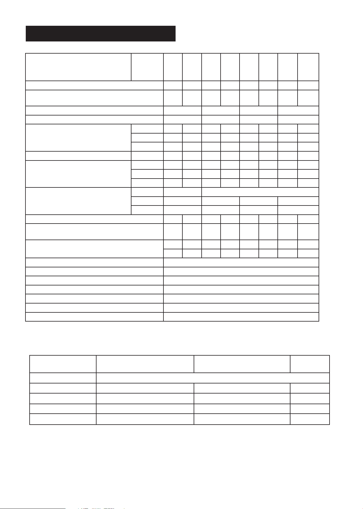
Table 4: Immersion allocation table
Commercial Cylinder
Volume (ltr)
Expansion Vessel
Size (ltr)
Mounting Kit Weights
400 - 500 60 Floor Mounted 12kg
800 100 Floor Mounted 17kg
1000 - 1250 150 Floor Mounted 24kg
1450 200 Floor Mouinted 38.5kg
2000 - 2500 300 Floor Mounted 41kg
Table 5: ErP data
Technical parameters in accordance with European Commission regulations 814/2013 and 812/2013
6kW 9kW 12kW 18kW 24kW 30kW 36kW 45kW 54kW
94110301 94110302 94110303 94110304 94110305 94110306 94110307 94110308 94110309
Upper
Lower
Upper
Lower
Upper
Lower
Upper
Lower
Upper
Lower
Upper
Lower
Upper
Lower
Upper
Lower
Upper
Lower
400L üüüüü
500L üüüüü
800L üüüüüüüü
1000L üüüüüüüü
1250L üüüüüüüüü
1450L üüüüüüüüü
2000L üüüüüüüüü
2500L üüüüüüüüü

7
Figure 1: General dimensions - Solar
Table 6: General dimensions table - Solar
Item Connection 400I 500I Connection 800I 1000I Connection 1250I 1450I Connection 2000I 2500I
ANA 1500 1800 N/A 1906 2301 N/A 1937 2253 N/A 2011 2416
B1/2"BSP 1090 1390 1/2" BSP 1502 1897 1/2" BSP 1419 1735 1/2" BSP 1423 1829
C1" BSP 870 898 1 1/4" BSP 997 997 1 1/2" BSP 1140 1137 1 1/2" BSP 1230 1230
D1" BSP 670 698 1 1/4" BSP 797 797 1 1/2" BSP 910 907 1 1/2" BSP 990 990
E1/2" BSP 630 650 1/2" BSP 774 747 1/2" BSP 835 835 1/2" BSP 905 733
F1" BSP 498 498 1 1/4" BSP 622 622 1 1/2" BSP 710 710 1 1/2" BSP 780 780
G1" BSP 323 323 1 1/4" BSP 447 447 N/A 530 530 1 1/2" BSP 600 601
H1" BSP 309 309 1 1/4" BSP 440 440 1 1/2" BSP 530 530 2" BSP 607 607
I1/2" BSP 524 524 1/2" BSP 601 601 1/2" BSP 695 695 1/2" BSP 778 778
JN/A 950 1004 N/A 1428 1811 N/A 1371 1371 N/A 1376 1780
K1/2" BSP 894 959 N/A
L1" BSP 980 1070 1" BSP 1187 1437 1" BSP 1176 1376 1" BSP 1226 1476
MN/A 1083 1383 N/A 1490 1885 N/A 1407 1723 N/A 1412 1817
NN/A 956 956 N/A 1107 1107 N/A 1308 1308 N/A 1560 1560
ON/A 872 872 N/A 1024 1024 N/A 1224 1224 N/A 1476 1476
K
L
M
I
J
H
G
F
E
D
C
B
A
N
O
45°
30°
40°
35°
3.3 Dimensions and connections
8
Thermostat Option 1
Zone valve
Switch out
G
L
Br Bl
N
0
Control High Limit
C
2
1C
1
2
o
o
o
+ C
0
S/L
o
o
o
o
+ C
0
L = Optional control utilising zone valve end
switch if required.
Figure 2: Wiring diagram 1
Figure 2a: Wiring diagram 2 - volt free option
Thermostat Option 2
Zone valve
Switch out
G
L
Br Bl
N
0
Control High Limit
C
2
1C
1
2
o
o
o
+ C
0
S/L
(volt free)
Switch out
Remove link
L
ooo
o
o
o
+ C
0
L = Optional control utilising zone valve end
switch if required.
WARNING
The high limit stat must always operate the zone valve in case of overtemperature.
NOTE: Option 2 untilises control thermostat to provide volt free control circuit.

9
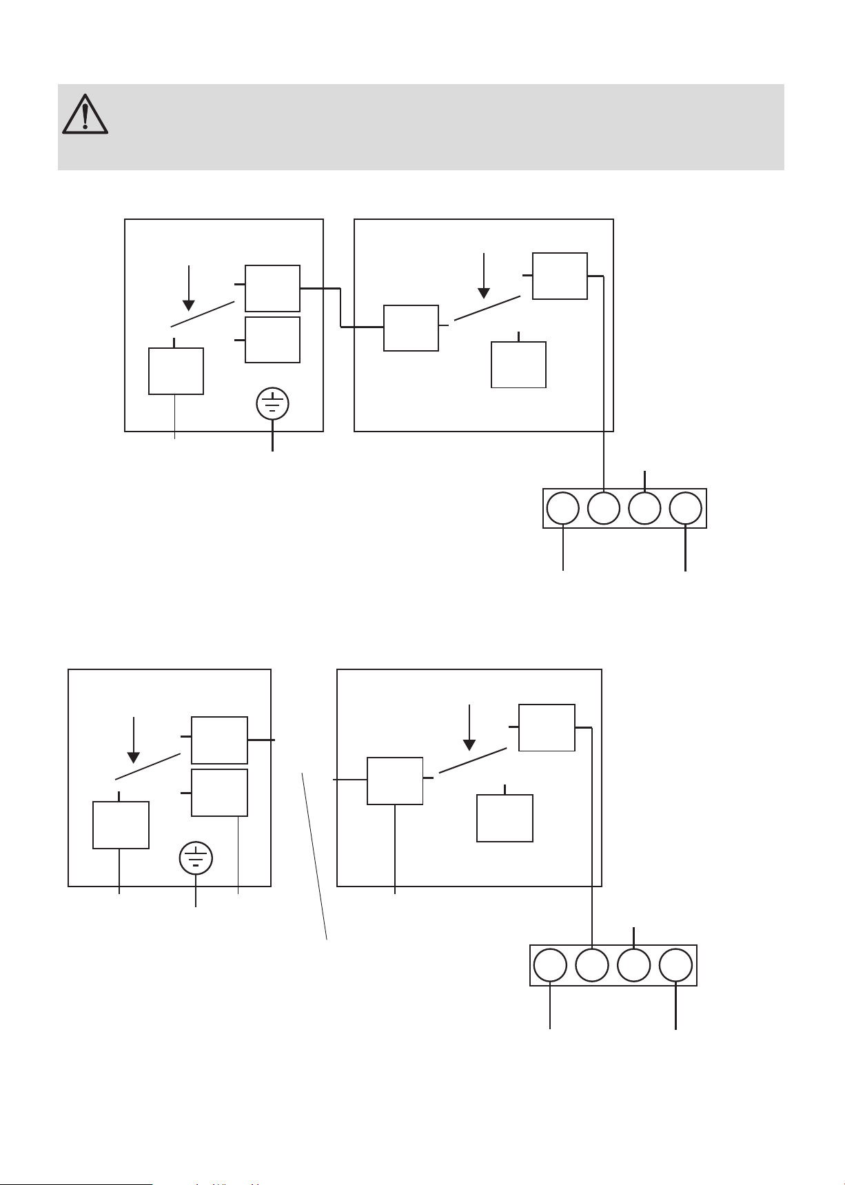
Neutral
Fuse
(not supplied)
Live
A
B
1
2
Fuse
(not supplied)
L1
L2
L3
Contactors
(not supplied)
Neutral
L1
Neutral
L2 L3
A
B
1
2
Earth
Earth
Neutral
Earth
Immersion Heater
Earth
Live
Immersion Heater
Contactors
(not supplied)
Note:
The 2 external contactors must be approved
components certified for 10,000 cycles of
operation for the contactor controlled by the
thermostat and at least 30 for the contactor
controlled by the non-self-resetting thermal
cut-out.
Line terminal
marked L1
Earth
Neutral terminal
marked 'N'
Line terminal
marked L3
Typical head layout for
a three phase heater
4
0
5
0
6
0
7
0
8
0
Line terminal
marked L2
Earth
Neutral terminal
marked 'N'
Live
marked ‘L’
Typical head layout for
a single phase heater
4
0
5
0
6
0
7
0
8
0
Cut-Out Temperature 80°C
(Factorey set)
1 2
1 - 2 16A 240V ~
Thermal cut-out
1 2
1 - 2 20A 240V ~
Temperature control
1 2
1 - 2 16A 240V ~
Thermal cut-out
1 2
1 - 2 20A 240V ~
Temperature control
Figure 2: Single phase wiring schematic
Figure 3: 3 phase wiring schematic

10
Hot outlet
Sensor pocket
Solar flow
Solar return
Auxiliary flow
Auxiliary return
Upper immersion
/ inspection hatch
T&P
connection
Secondary
return
Sensor
pocket
Cold
inlet
4. Description of the product
4.1 General description
This product is a purpose designed unvented water
heater. The unit has a stainless steel inner vessel,
which ensures an excellent standard of corrosion
resistance. The outer casing is a combination of resilient
thermoplastic mouldings and soft jacket. All products
are insulated with CFC free polyurethane foam to give
good heat loss protection.
The unit is supplied complete with all the necessary
safety and control devices needed to allow connection
to the cold water mains. All these components are
preset and should not be tampered with.
4.2 Operation principle
The unvented cylinder is used to heat and store hot
water for use in commercial applications.
Depending on the model the water can be heated
directly using an element (supplied separately) or
indirectly through a coil in the unit using an indirect heat
source.
To provide pressure to the tap or shower an unvented
unit uses the incoming mains water pressure. To do this
the cylinder is sealed and not vented. However, when
the volume of water is heated it expands and without
any room for expansion could cause the cylinder to
rupture and fail. To allow expansion of this heated
water it is important that an expansion vessel is used.
This vessel is pressurised and gives the heated water
room to expand.
4.3 Main components
See Figure 4: Main components
4.4 Standard delivery
The delivery includes:
`Cylinder
`Literature pack
`Instructions (inc benchmark commissioning
checklist & service record)
`Cold water control pack (see table 2 page 5)
`Expansion vessel (see table 3 page 6)
`Combination valve (inc pressure reducing valve,
pressure relief valve and check valve)
`Tundish
`2 port zone valve.
Figure 4: Main components
Note: This is an indirect unit and shows the general
position of components but these will change depending
on the model.
11
5. Before installation
5.1 Installation regulations
5.2 Installation requirements
Water supply
In an unvented system the pressure and owrate is
directly related to the incoming water supply. For this
reason it is recommended that the maximum water
demand is assessed and the water supply checked to
ensure this demand can be satisfactorily met.
`We suggest the minimum supply requirements
should be 0.15MPa (1.5 bar) pressure and 100
litres per minute ow rate.
`A 28mm cold water supply is recommended,
however, if a smaller supply exists, which provides
sufcient ow, this may be used (although more
ow noise may be experienced).
`The higher the available pressure and ow rate the
better the system performance.
`See table 1 on page 5 for cylinder operating
pressures. This is controlled by the cold water
combination valve assembly.
Outlet/terminal ttings (taps, etc.)
`The cylinder can be used with most types of
terminal ttings.
`Outlets situated higher than the cylinder will give
outlet pressures lower than that at the heater, a
10m height difference will result in a 1 bar pressure
reduction at the outlet.
`All ttings, pipework and connections must have a
rated pressure of at least 8 bar at 80°C.
Limitations
The cylinder should not be used in association with any
of the following:
`Solid fuel boilers or any other boiler in which the
energy input is not under effective thermostatic
control, unless additional and appropriate safety
measures are installed.
`Ascending spray type bidets or any other class 1
back syphonage risk requiring that a type A air gap
be employed.
`Steam heating plants unless additional and
WARNING
Installation of the appliance must be carried
out by a qualied engineer in accordance
with prevailing and national regulations as
listed below.
`Building Regulations
`The Building Standards (Scotland)
`The Building Regulations (Northern
Ireland)
`I.E.E Electrical Regs
`UK Water Regulations
appropriate safety devices are installed.
`Situations where maintenance is likely to be
neglected or safety devices tampered with.
`Water supplies that have either inadequate
pressure or where the supply may be intermittent.
`Situations where it is not possible to safely pipe
away any discharge from the safety valves.
`In areas where the water consistently contains a
high proportion of solids, e.g. suspended matter
that could block the strainer, unless adequate
ltration can be ensured.
`In areas where the water supply contains chloride
levels that exceed 250mg/l.
The solar cylinder must be incorporated into a fully
pumped solar primary circuit. Control of the solar
primary is achieved by the use of external controls not
supplied with the unit. Control must be via a purpose
designed solar hydraulic station and solar differential
temperature controller.
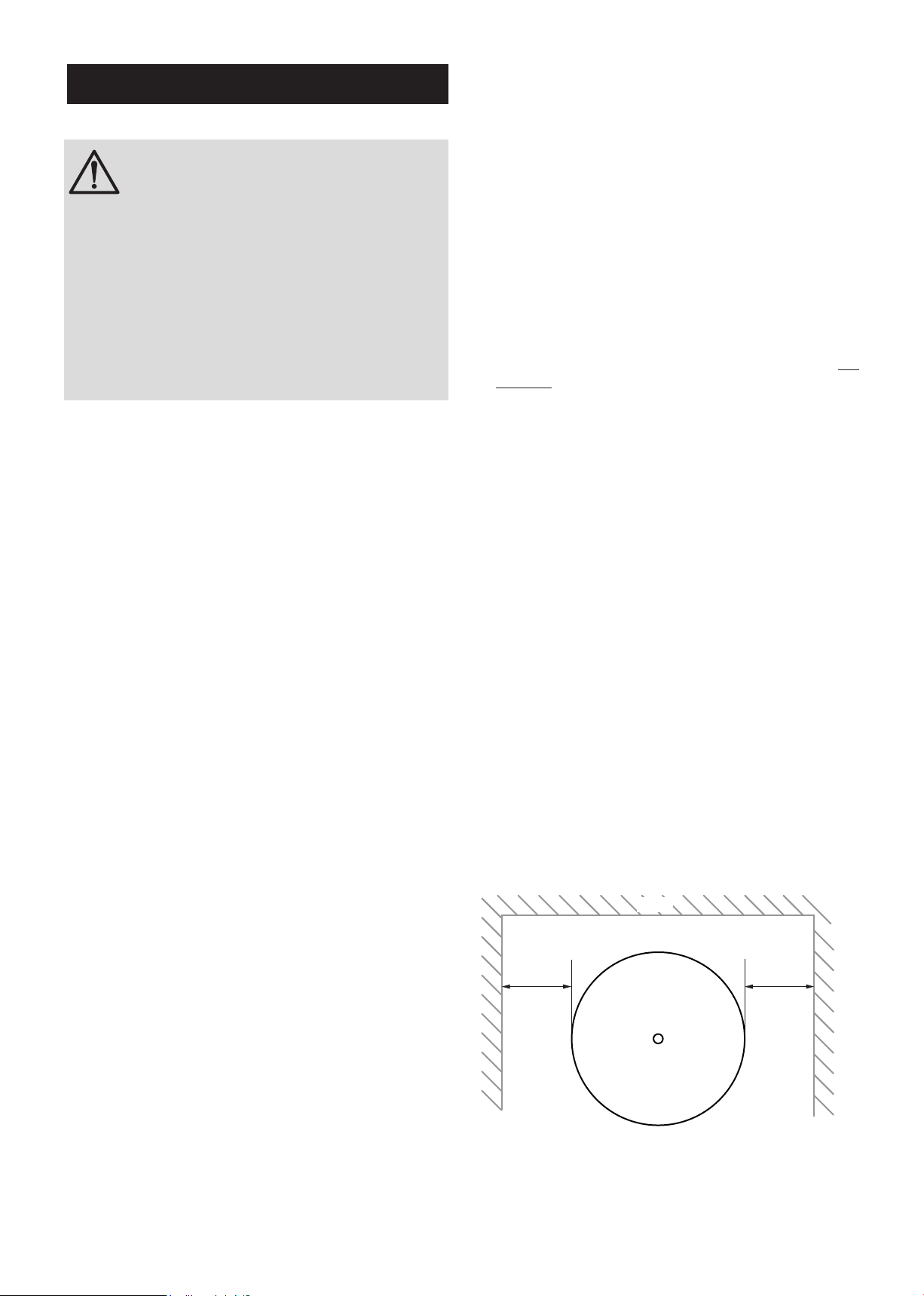
5.3 Choice of location
The cylinder must be vertically oor mounted. Although
location is not critical, the following points should be
considered:
`The cylinder should be sited to ensure minimum
dead leg distances, particularly to the point of most
frequent use.
`Avoid siting where extreme cold temperatures will
be experienced. All exposed pipe work should be
insulated.
`The discharge pipework from the safety valves
must have minimum fall of 1:200 from the unit and
terminate in a safe and visible position.
`Access to associated controls and immersion
heaters must be available for the servicing and
maintenance of the system. Where these controls
are installed against a wall a minimum distance of
250mm must be left.
`Ensure that the oor area for the cylinder is level
and capable of permanently supporting the weight
when full of water (see table 1, page 5 for weights).
Figure 5: Siting the unit
Min 250mm
Wall
Min 250mm
12
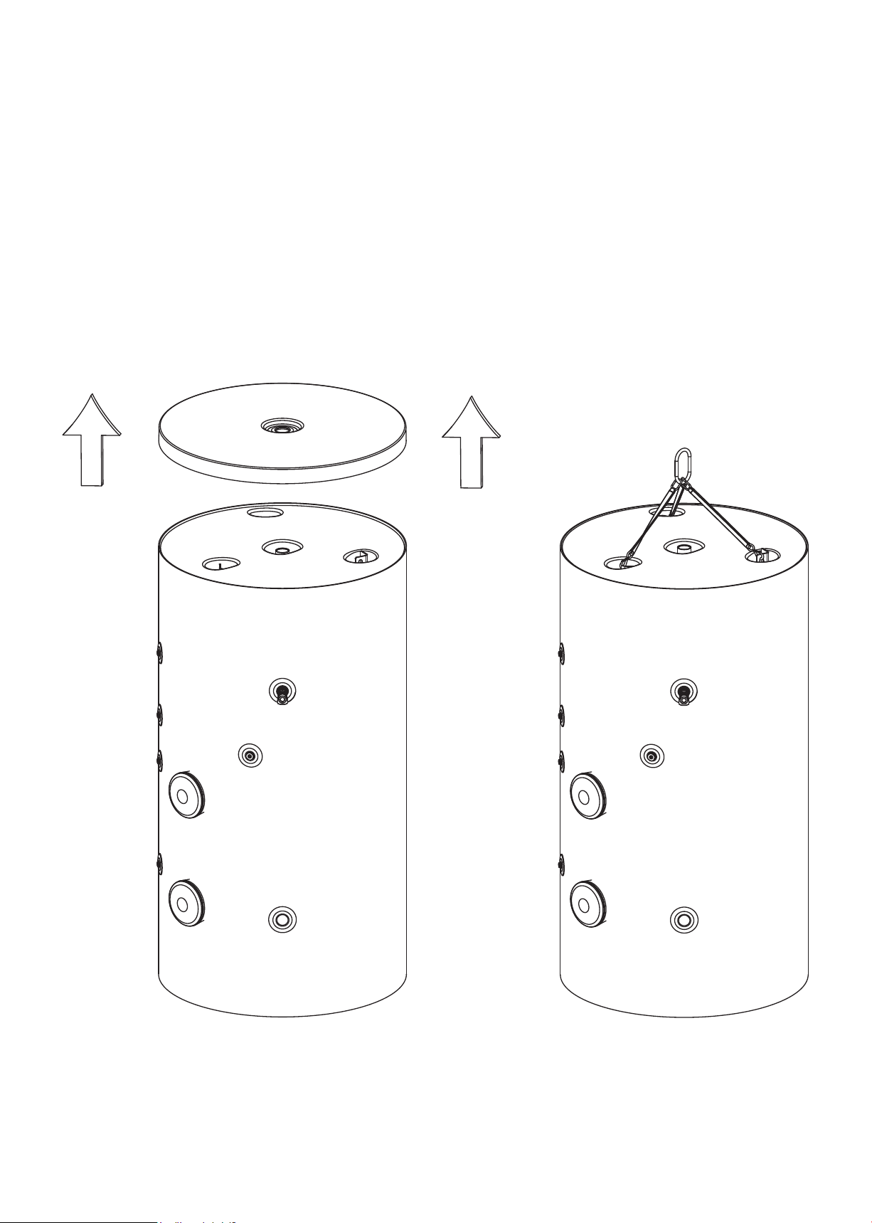
Figure 8: Lifting the unit
5.4 Transport
Prior to installation the unit should be stored and
transported in an area free from excessive damp or
humidity.
To aid installation, the water heater (800ltr upwards)
is provided with lifting points, located at the top of the
unit. To access the lifting eyes please remove the top
outlet grommet followed by the cylinder lid.

13
6.2 Water connections
WARNING
`Under no circumstances should the
factory tted temperature/pressure
relief valve be removed other than
by a competent person. To do so will
invalidate any guarantee or claim.
`The cold water combination valve
assembly must be tted on the mains
water supply to the cylinder.
`No control or safety valves should be
tampered with or used for any other
purpose.
`The discharge pipe should not be
blocked or used for any other purpose.
`The tundish should not be located
adjacent to any electrical components.
Refer to the installation schematic (g 6) for details on
the pipework layout. Specic details for the discharge
pipework layout is also provided in gure 8.
`All pipe ttings are made via BSP female pipe
connections directly to the unit.
`Astopcock or servicing valve should be incorporated
into the cold water supply to enable the cylinder and
its associated controls to be isolated and serviced
(not supplied).
`The expansion vessel must be connected between
6. Installation
6.1 General
After reading the previous sections in this booklet, and
choosing a good location for the unit, please install,
paying attention to the following hydraulic, electrical
and commissioning sections.
Boiler selection
`The boiler should have a control thermostat and non
self-resetting thermal cut-out and be compatible
with unvented storage water heaters.
`Where use of a boiler without a thermal cut-out
is unavoidable a “low head” open vented primary
circuit should be used. The feed and expansion
cistern head above the cylinder should not exceed
2.5m.
`Can be a sealed system or open vented type -
maximum primary pressure 3 bar.
`The boiler cannot be vented through the cylinder.
Figure 6: Typical installation schematic (not to scale)
WRAS approved
pump
Check valve
Air vent at highest
point in system
(not supplied)
To Drain
Hot water outlet
Direction
of flow
De-stratification pump
TYPICAL DE-STRATIFICATION
LOOP SYSTEM
Please note, that this is a typical installation and
other options are available.
Check Valve (not supplied)
Mains water
supply
Expansion
vessel
Balanced cold
water connection
Pressure reducing
valve
Pressure relief
valve
Discharge
pipe
Tundish
SECONDARY CIRCULATION
Secondary
return
Solar flow out
Solar flow in
Auxillary flow in
Auxillary flow out

14
3.5 bar Pressure
reducing valve
Mains water in
8 bar Pressure
relief valve
28mm compression connections
To cylinder
Pressure relief
discharge
Take note of ow
direction
Take note of ow
direction
Pressure gauge
connections (one
each side)
the cold water combination valve and the cylinder.
`The location of the expansion vessel should allow
access to recharge the pressure as and when
necessary.
`A suitable draining tap should be installed in the
cold water supply to the cylinder between the
expansion valve and the heater at as low a level
as possible.
`It is recommended that the outlet point of the drain
pipework be at least 1 metre below the level of the
heater (this can be achieved by attaching a hose to
the drain tap outlet spigot).
Cold water control pack
CAUTION
`The expansion vessel pressure must
be set in accordance with the inlet
pressure set on the pressure reducing
valve.
`Flush supply pipework before
connection to remove all ux and debris
prior to tting the inlet controls. Failure
to do this may result in irreparable
damage to the controls and will
invalidate any warranty.
`The cold water control pack can be connected
anywhere on the cold water cylinder supply prior to
the expansion vessel.
`The control pack incorporates the strainer, check
valve, core unit and expansion releif valve.
`The pressure settings are adjustable and should
be set between 1 & 6 bar.
`The valve can be tted in any orientation to suit
the installation as long as the valve is installed with
the direction of ow arrows pointing in the correct
direction.
`The expansion relief valve should be installed with
the discharge pipework in either the horizontal
position or facing downwards.
`No other valves should be placed between the cold
water combination valve and the cylinder.
`The blank plastic plugs in the body of the pressure
relief valve are pressure gauge connections to
enable pressure monitoring to be carried out, should
the system develop a fault. It is recommended that
these be accessible (the pressure reducing valve
has two – only one need be accessible).
Auxiliary circuit control
`The 2 port motorised valve supplied with the
cylinder MUST be tted on the auxiliary ow to the
cylinder heat exchanger and wired such that in the
event of the cylinder overheating it will close the
auxiliary circuit.
`Auxiliary circulation to the cylinder heat exchanger
must be pumped; gravity circulation WILL NOT
WORK.
`It is reccomended that an air bleed or automatic air
vent is incorporated in the primary return pipe work
close to the unit.
`Boiler ow temperature should be set to 82°
(maximum ow temperature to auxiliary heat
exchanger 89°C).
Figure 7: Cold water combination valve (400 & 500ltr)

15
Solar connections
`The lower (solar) coil must be connected to a
fully pumped solar primary circuit with its own
safety control which must be installed as per the
manufacturers instructions.
`There must be suitable check vales installed in
the solar primary ow and return to prevent the
possibility of any thermo-syphoning if the solar
circulation is stopped.
Secondary circulation
If secondary circulation is required it is recommended
that it be connected to the cylinder as shown (see g.
6).
`The secondary return pipe should be in 28mm pipe
and incorporate a check valve to prevent backow.
`A suitable WRAS approved bronze circulation
pump will be required.
`On large systems, due to the increase in system
water content, it may be necessary to t an
additional expansion vessel to the secondary
circuit. This should be done if the capacity of the
secondary circuit exceeds 10 litres.
Pipe capacity (copper):
15mm O.D. = 0.13 l/m (10 litres = 77m)
22mm O.D. = 0.38 l/m (10 litres = 26m)
28mm O.D. = 0.55 l/m (10 litres = 18m)
Note: Plastic pipe capacities may be reduced due to
thicker wall sections.
De-stratication kits
The correct size of de-stratication kit must be used
with your cylinder to ensure the volume can be
circulateed in 1 hour. The pump instructions will need
to be reviewed for information on the correct setting.
Please follow the installation schematic below for
guidance. When the system circulates needs to be
specied by the installer to ensure water is not drawn
off during the de-stratication process. If a hot water
demand is required during this period cold water may
be discharged from the hot outlet. It is recommended
that a check valve be installed before the pump to stop
any rick of cold water draw off through the pump when
it is not in use.
For guidance on installation please refer to gure 6.
Discharge
It is a requirement of Building Regulation G3 that any
discharge from an unvented system is conveyed to
where it is visible, but will not cause danger to persons in
or about the building. The tundish and discharge pipes
should be tted in accordance with the requirements
and guidance notes of Building Regulation G3. The G3
Requirements and Guidance section 3.50 - 3.63 are
reproduced in the following sections of this manual.
For discharge pipe arrangements not covered by G3
Guidance advice should be sought from your local
Building Control Ofcer. Any discharge pipe connected
to the pressure relief devices (expansion valve and
temperature/pressure relief valve) must be installed in
a continuously downward direction and in a frost free
environment.
Water may drip from the discharge pipe of the
pressure relief device. This pipe must be left open to
the atmosphere. The pressure relief device is to be
operated regularly to remove lime deposits and to
verify that it is not blocked.
G3 REQUIREMENT
“...there shall be precautions...to ensure that the
hot water discharged from safety devices is safely
conveyed to where it is visible but will not cause danger
to persons in or about the building.”
The following extract is taken from the latest G3
Regulations
Discharge pipes from safety devices
Discharge pipe D1
3.50 Each of the temperature relief valves or combined
temperature and pressure relief valves specied in
3.13 or 3.17 should discharge either directly or by way
of a manifold via a short length of metal pipe (D1) to a
tundish.
3.51 The diameter of discharge pipe (D1) should be
not less than the nominal outlet size of the temperature
relief valve.
3.52 Where a manifold is used it should be sized to
accept and discharge the total discharge from the
discharge pipes connected to it.
3.53 Where valves other than the temperature and
pressure relief valve from a single unvented hot water
system discharge by way of the same manifold that
is used by the safety devices, the manifold should be
factory tted as part of the hot water storage system
unit or package.
Tundish
3.54 The tundish should be vertical, located in the
same space as the unvented hot water storage system
and be tted as close as possible to, and lower than,
the valve, with no more than 600mm of pipe between

16
the valve outlet and the tundish (see g 8).
Note: To comply with the Water Supply (Water Fittings)
Regulations, the tundish should incorporate a suitable
air gap.
3.55 Any discharge should be visible at the tundish. In
addition, where discharges from safety devices may
not be apparent, e.g. in dwellings occupied by people
with impaired vision or mobility, consideration should
be given to the installation of a suitable safety device
to warn when discharge takes place, e.g. electronically
operated.
Discharge pipe D2
3.56 The discharge pipe (D2) from the tundish should:
(a) have a vertical section of pipe at least 300mm
long below the tundish before any elbows or bends in
the pipework (see g. 8); and
(b) be installed with a continuous fall thereafter of at
least 1 in 200.
3.57 The discharge pipe (D2) should be made of:
(a) metal; or
(b) other material that has been demonstrated to be
capable of safely withstanding temperatures of the water
discharged and is clearly and permanently marked to
identify the product and performance standard (e.g. as
specied in the relevant part of BS 7291).
3.58 The discharge pipe (D2) should be at least one
pipe size larger than the nominal outlet size of the safety
device unless its total equivalent hydraulic resistance
exceeds that of a straight pipe 9m long, i.e. for discharge
pipes between 9m and 18m the equivalent resistance
length should be at least two sizes larger than the
nominal outlet size of the safety device; between 18
and 27m at least 3 sizes larger, and so on; bends must
be taken into account in calculating the ow resistance.
See Fig 11, Table 4 and the worked example.
Note: An alternative approach for sizing discharge
pipes would be to follow Annex D, section D.2 of BS
6700:2006 Specication for design, installation, testing
and maintenance of services supplying water for
domestic use within buildings and their curtilages.
3.59 Where a single common discharge pipe serves
more than one system, it should be at least one pipe
size larger than the largest individual discharge pipe
(D2) to be connected.
3.60 The discharge pipe should not be connected to a
soil discharge stack unless it can be demonstrated that
the soil discharge stack is capable of safely withstanding
temperatures of the water discharged, in which case, it
should:
(a) contain a mechanical seal, not incorporating a
water trap, which allows water into the branch pipe
without allowing foul air from the drain to be ventilated
through the tundish;
(b) be a separate branch pipe with no sanitary
appliances connected to it;
(c) if plastic pipes are used as branch pipes carrying
discharge from a safety device they should be either
polybutylene (PB) to Class S of BS 7291-2:2006 or
cross linked polyethylene (PE-X) to Class S of BS
7291-3:2006; and
(d) be continuously marked with a warning that no
sanitary appliances should be connected to the pipe.
Note:
1. Plastic pipes should be joined and assembled with
ttings appropriate to the circumstances in which they
are used as set out in BS EN ISO 1043-1.
2. Where pipes cannot be connected to the stack it
may be possible to route a dedicated pipe alongside or
in close proximity to the discharge stack.
Termination of discharge pipe
3.61 The discharge pipe (D2) from the tundish should
terminate in a safe place where there is no risk to
persons in the vicinity of the discharge.
3.62 Examples of acceptable discharge arrangements
are:
(a) to a trapped gully with the end of the pipe below a
xed grating and above the water seal;
(b) downward discharges at low level; i.e. up to
100mm above external surfaces such as car parks,
hard standings, grassed areas etc. are acceptable
providing that a wire cage or similar guard is positioned
to prevent contact, whilst maintaining visibility; and
(c) discharges at high level: e.g. into a metal hopper
and metal downpipe with the end of the discharge pipe
clearly visible or onto a roof capable of withstanding
high temperature discharges of water and 3m from
any plastic guttering system that would collect such
discharges.
3.63 The discharge would consist of high temperature
water and steam. Asphalt, roong felt and non-
metallic rainwater goods may be damaged by such
discharges.
Worked example of discharge pipe sizing
Fig. 11: shows a G1/2 temperature relief valve with a
discharge pipe (D2) having 4 No. elbows and length of
7m from the tundish to the point of discharge.
From Table 4:
Maximum resistance allowed for a straight length of
22mm copper discharge pipe (D2) from a G1/2
temperature relief valve is 9.0m.
Subtract the resistance for 4 No. 22mm elbows at 0.8m
each = 3.2m
Therefore the permitted length equates to: 5.8m
5.8m is less than the actual length of 7m therefore
calculate the next largest size.
17
Maximum resistance allowed for a straight length of
28mm pipe (D2) from a G1/2 temperature relief valves
equates to 18m.
Subtract the resistance of 4 No. 28mm elbows at 1.0m
each = 4.0m
Therefore the maximum permitted length equates to:
14m
As the actual length is 7m, a 28mm (D2) copper pipe
will be satisfactory.
Valve
Outlet Size
Minimum Size Of
Discharge Pipe
D1
Minimum Size Of
Discharge Pipe D2
From Tundish
Maximum Resistance
Allowed, Expressed As A
Length Of Straight Pipe
(I.E. No Elbows Or Bends)
Resistance
Created By Each
Elbow Or Bend
G1/2 15mm
22mm
28mm
35mm
up to 9m
up to 18m
up to 27m
0.8m
1.0m
1.4m
G3/4 22mm
28mm
35mm
42mm
up to 9m
up to 18m
up to 27m
1.0m
1.4m
1.7m
G1 28mm
35mm
42mm
54mm
up to 9m
up to 18m
up to 27m
1.4m
1.7m
2.3m
Table 7: Sizing of copper discharge pipe (D2) for common temperature relief valve outlet sizes
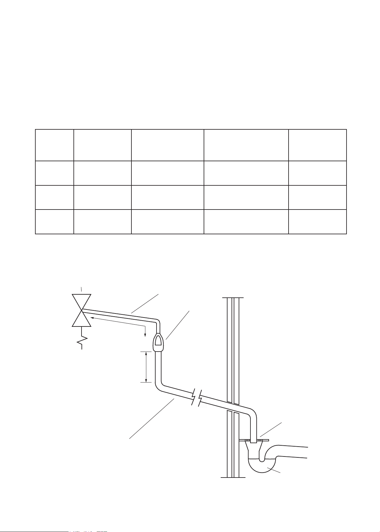
Safety device
(e.g. Temperature
relief valve) Metal discharge pipe (D1) from
Temperature relief valve to tundish
Tundish
Discharge below
fixed grating
(Building Regulation
G3 section 3.61 gives
alternative points
of discharge)
Fixed grating
Trapped
gully
600mm maximum
300mm
minimum
Discharge pipe (D2) from tundish,
with continuous fall. See Building
Regulation G3 section 3.56,
Table 1 and worked example
Figure 8: Typical discharge pipe arrangement (extract from Building Regulation G3 Guidance Section 3.50)

18
6.3 Electrical connections
In case of difculty contact service support; contact
details are available on page 32 of this booklet.
WARNING
`Disconnect from the mains electrical
supply before removing any covers.
`Never attempt to replace the
immersion heater(s) other than with the
recommended immersion heater(s).
`DO NOT bypass the thermal cut-out(s) in
any circumstances. All electrical wiring
should be carried out by a competent
electrician and be in accordance with
the latest I.E.E Wiring Regulations.
`Each circuit must be protected by a
suitable fuse and double pole isolating
switch with a contact separation of at
least 3mm in both poles.
`DO NOT operate the immersion heaters
until the cylinder has been lled with
water.
`The immersion heater(s) should be wired in
accordance with g's 2 and 3, page 9.
`All immersion heaters are tted with a thermostat
which is tted in the centre of the heater plate and a
cut-out which is tted to the side of the thermostat.
These MUST be wired in series with the operating
coil circuit of the contactor (not supplied).
Space and heating systems controls
`The controls provided with the cylinder will ensure
the safe operation of the unit within the central
heating system. Other controls will be necessary to
control the space heating requirements and times
that the system is required to function.
`The cylinder is compatible with most heating
controls. Please refer to the controls manufacturers
instructions, supplied with the controls selected.
6.4 Filling the installation
`Check expansion vessel pre-charge pressure.
The expansion vessel pressure must be set in
accordance with the inlet pressure set on the
pressure reducing valve.
`Ensure the drain cock is CLOSED.
`Open a hot tap furthest from the cylinder.
`Open the mains stop cock to ll the unit. When
water ows from the tap, allow to run for a few
minutes to thoroughly ush through any residue,
dirt or swarf, then close the tap.
`Open successive hot taps to purge the system of
air.

19
7. Commissioning
7.1 General
After lling the installation with water in the previous
section please follow the following steps to complete
the installation of the unit.
WARNING
DO NOT operate the immersion heaters or
primary circuit until the cylinder has been
lled with water.
7.2 Checklist before commissioning
`Check all water connections for leaks and rectify
as necessary.
`Turn off mains water supply.
`Remove the pressure reducing valve head work to
access the strainer mesh, clean and re-t.
`Turn the water supply back on.
`Manually open, for a few seconds, each relief valve
in turn, checking that water is discharged and runs
freely through the tundish and out at the discharge
point.
`Ensure that the valve(s) reseat satisfactorily.
7.3 Commissioning procedure
`Fill the solar primary circuit following the instructions
provided with the solar hydraulic controls.
`Heating of the solar coil is controlled by the solar
controller; refer to the manufacturer's instructions
for details.
`The solar controller should be programmed to give
a cylinder temperature of approximately 65°C.
`Fill the auxiliary circuit following the boiler
manufacturer’s commissioning instructions.
`To ensure the cylinder auxiliary heat exchanger is
lled, the 2 port motorised valve (supplied) should
be manually opened by moving the lever on the
motor housing to the MANUAL setting. When
the primary circuit is full return the lever to the
AUTOMATIC position.
`Switch on the boiler, ensure the programmer is set
to Hot Water and allow the cylinder to heat up to a
normal working temperature 65oC.
`If necessary the temperature can be adjusted as
shown in Figure 9. The minimum thermostat setting
is 10°C.
`Check the operation of the thermostat and 2 port
motorised valve, and that no water has issued from
the expansion relief valve or temperature/pressure
relief valve during the heating cycle.
0
30
40
50
60
70
°C
Temperature control
clockwise to increase,
counter-clockwise to
decrease
Thermal cut-out
reset under cap
Figure 9: Indirect controls (auxiliary coil)
Benchmark
The cylinder is covered by the Benchmark Scheme
which aims to improve the standards of installation
and commissioning of domestic heating and hot water
systems in the UK and to encourage regular servicing
to optimise safety, efciency and performance.
Benchmark is managed and promoted by the Heating
and Hotwater Industry Council. For more information
visit www.centralheating.co.uk.
Please ensure that the installer has fully completed the
Benchmark Checklist (page 30 & 31) of this manual and
that you have signed it to say that you have received a
full and clear explanation of its operation. The installer is
legally required to complete a commissioning checklist
as a means of complying with the appropriate Building
Regulations (England & Wales).
All installations must be notied to Local Area Building
Control either directly or through a Competent
Persons Scheme. A Building Regulations Compliance
Certicate will then be issued to the customer who
should, on receipt, write the Notication Number on the
Benchmark Checklist.
This product should be serviced regularly to optimise
its safety, efciency and performance. The service
engineer should complete the relevant Service Record
on the Benchmark Checklist after each service.
The Benchmark Checklist may be required in the event
of any warranty work.

20
8. Operation
8.1 General
WARNING
`If water discharges from the
temperature/pressure relief valve on
the cylinder shut down the heat source.
Do not turn off any water supply. Contact
a competent installer for unvented water
heaters to check the system.
`Do not tamper with any of the safety
valves tted to the system. If a fault
is suspected contact a competent
installer.
`DO NOT bypass the thermal cut-out(s)
in any circumstances.
Flow performance
When initially opening hot outlets a small surge in
ow may be noticed as pressures stabilise. This is
quite normal with unvented systems. In some areas
cloudiness may be noticed in the hot water. This is due
to aeration of the water, is quite normal and will quickly
clear.
Temperature controls
The cylinder units are tted with a thermostat and
thermal cut-out. These controls must be wired in
series with the 2 port motorised zone valve supplied
to interrupt the ow of primary water around the heat
exchanger coil when the control temperature has been
reached.
DO NOT bypass the thermal cut-out(s) in any
circumstances.
The solar cylinder must be incorporated into a fully
pumped solar primary circuit. Control of the solar
primary is achieved by the use of external controls not
supplied with the unit. Control must be via a purpose
designed solar hydraulic station and solar differential
temperature controller.
Operational faults
Operational faults and their possible causes are
detailed in the Fault Finding section (p.23) of this book.
It is recommended that faults should be checked by a
competent installer.
The air volume within the expansion vessel will
periodically require recharging to ensure expanded
water is accommodated within the system. A discharge
of water INTERMITTENTLY from the expansion valve
will indicate the air volume has reduced to a point
where it can no longer accommodate the expansion.
This manual suits for next models
15
Table of contents
Popular Inverter manuals by other brands


Ross
Ross RPG6250RCD manual

Generac Power Systems
Generac Power Systems QuietSource 005028-0 owner's manual

AirMan
AirMan SG Series instruction manual

Champion
Champion ParaLink 100468 Operator's manual

ECO-WORTHY
ECO-WORTHY CSP600 user manual

Badger Power Electronics
Badger Power Electronics BPE-HI-3.6K user manual


