Badger Power Electronics BPE-HI-3.6K User manual

HYBRID INVERTER
SOLAR/STORAGE/WIND/
BACK-UP GENERATOR
USER MANUAL
BPE-HI-3.6K & BPE-HI-5K

Contents Contents
………………………………………………
………………………………………………
……………………………………………………………
……………………………………………………………
……………………………………………………
01
01-04
27-29
33-34
04-16
17
18-27
Contents
1. Safety Introduction
2. Product instructions
2.1 Product Overview
2.2 Product Features
2.3 Basic System Architecture
3. Installation
3.1 Parts list
3.2 Mounting instructions
3.3 Battery connection
3.4 AC Input/Output Connection
3.5 PV Connection
3.6 CT Connection
3.7 Earth Connection(mandatory)
3.8 WIFI Connection
3.9 Wiring System for Inverter
3.10 Single phase parallel connection diagram
3.11Three phase Parallel Inverter
4. OPERATION
4.1 Power ON/OFF
4.2 Operation and Display Panel
5. LCD Display Icons
5.1 Main Screen
5.2 Solar Power Curve
5.3 Curve Page-Solar & Load & Grid
5.4 System Setup Menu
5.5 Basic Setup Menu
5.6 Battery Setup Menu
5.7 System Work Mode Setup Menu
29-32
30-31
5.8 Grid Setup Menu
5.9 Wind Turbine Connection
5.10 Generator Port Use Setup Menu
5.11 Advanced Function Setup Menu
5.12 Smart Load
Mode ……………………………………………………………………
Fault information and processing …………………………………
Limitation of Liability …………………………………………………
Datasheet ………………………………………………………………
WIFI/GPRS dongle installation and Solarman remote
monitoring setup

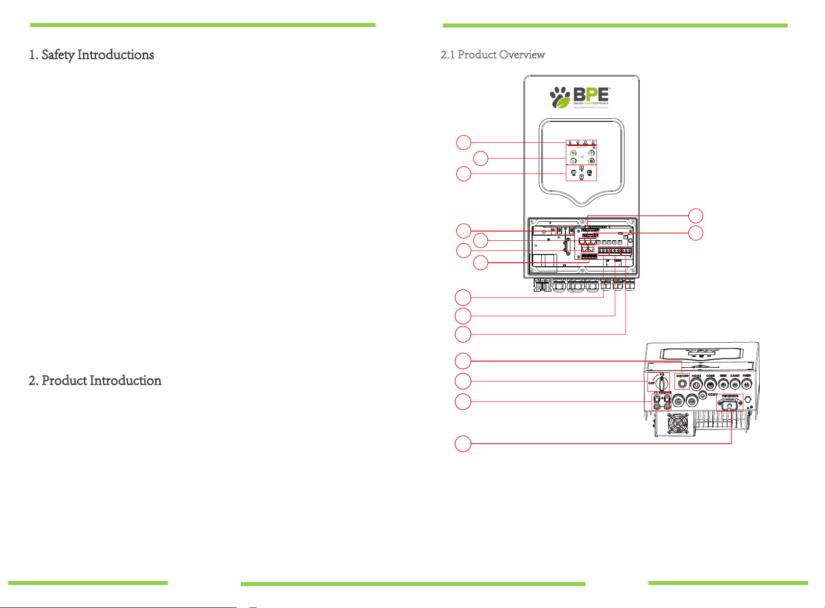
Programming Quick Start
Guide BPE Hybrid Inverter
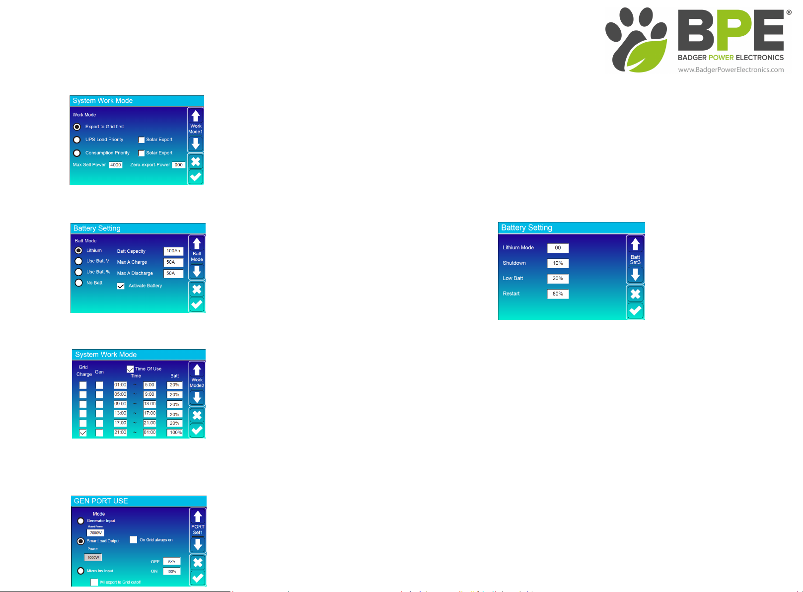
System Work Mode
Battery Settings - Time Of Use
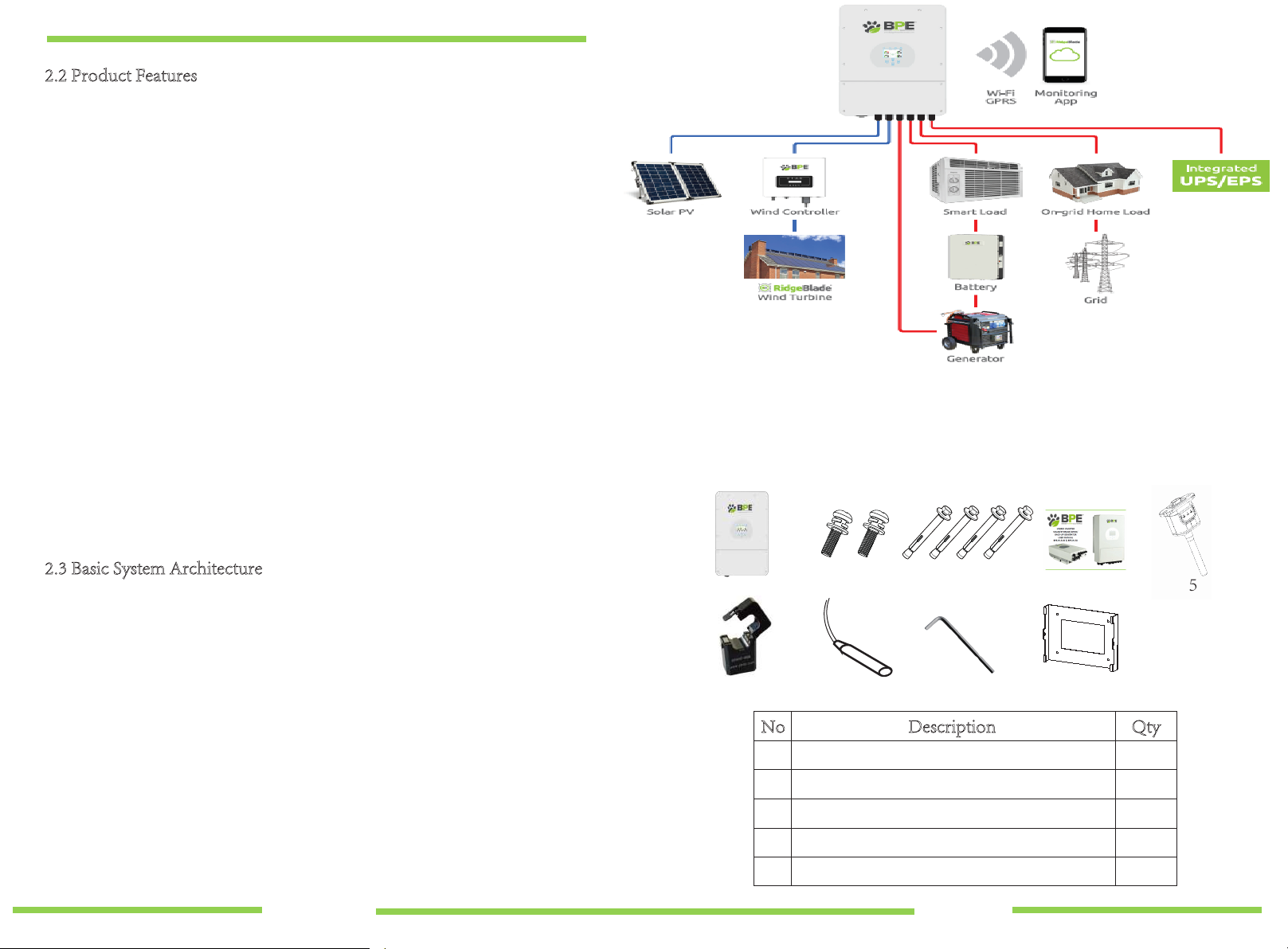
'EWKZdh^
Home Screen > System Work Mode
Export to Grid First - All excess power will be exported to the grid.
UPS Load Priority - The hybrid inverter will only power the loads connected to the load port and will not produce more power than the connected loads require.
This mode by default will export ZERO to the grid unless "Solar Export" is ticked.
Consumption Priority - The hybrid inverter will push power to the whole home load (this mode requires the included CT clamp) see page 13 of the user manual.
This mode by default will export ZERO to the grid unless "Solar Export" is ticked. WƌĞƐƐƚŚĞƚŝĐŬĂƚƚŚĞďŽƚƚŽŵŽĨƚŚĞƐĐƌĞĞŶƚŽƐĂǀĞLJŽƵƌƐĞůĞĐƚŝŽŶ
Home Screen > Battery Settings
Home Screen > System Work Mode > Arrow Down > Time Of Use Settings
This screen will allow you to set the parameters for discharging the battery
to the load and also charging the battery from the grid or a generator.
Once you have completed the above step and activated the Lithium battery
you will need to programme the time of use settings, selecting Time Of Use
will allow the battery to be discharged to the load until a user set SOC % is reached during the pre-set 6 time periods. You can also select whether you
want to charge the battery from the Grid or a Generator. For example, on the image to the left we have programmed the time of use to discharge the battery to the load
between 01.00am - 21.00pm until the battery SOC reaches 20% and then for the grid to fully charge the battery between 21.00pm and 01.00am. WƌĞƐƐƚŚĞƚŝĐŬĂƚƚŚĞ
ďŽƚƚŽŵŽĨƚŚĞƐĐƌĞĞŶƚŽƐĂǀĞLJŽƵƌƐĞůĞĐƚŝŽŶ
Home Screen > Gen Port Use
dŚĞ'EWKZdŝƐĂŵƵůƚŝĨƵŶĐƚŝŽŶŝŶƉƵƚŽƵƚƉƵƚŽĨĨĞƌŝŶŐϯĚŝĨĨĞƌĞŶƚĨƵŶĐƚŝŽŶƐ zŽƵĐĂŶƐĞůĞĐƚŽŶĞŽĨƚŚĞĨŽůůŽǁŝŶŐ
'ĞŶĞƌĂƚŽƌ/ŶƉƵƚ
^ŵĂƌƚ>ŽĂĚKƵƚƉƵƚͲdŚŝƐŵŽĚĞƵƚŝůŝƐĞƐƚŚĞ'ĞŶŝŶƉƵƚĐŽŶŶĞĐƚŝŽŶĂƐĂ^ŵĂƌƚ>ŽĂĚŽƵƚƉƵƚǁŚŝĐŚŽŶůLJƌĞĐĞŝǀĞƐƉŽǁĞƌǁŚĞŶƚŚĞƌĞŝƐĞdžĐĞƐƐƉŽǁĞƌŐĞŶĞƌĂƚŝŽŶĂŶĚƚŚĞďĂƚƚĞƌLJ
^KŝƐĂďŽǀĞĂƵƐĞƌƉƌŽŐƌĂŵŵĂďůĞƚŚƌĞƐŚŽůĚ dŚĞ'ĞŶŝŶƉƵƚƉŽƌƚŝŶƚŚĞƵƐĞƌĂƌĞĂŽĨƚŚĞƐLJƐƚĞŵďĞĐŽŵĞƐĂŶŽƵƚƉƵƚƚŽŚŝŐŚƉŽǁĞƌůŽĂĚƐƐƵĐŚĂƐĂǁĂƚĞƌŚĞĂƚĞƌŝƌƌŝŐĂƚŝŽŶ
ƉƵŵƉĂĐƵŶŝƚŽƌĂŶLJŽƚŚĞƌĚĞǀŝĐĞ
DŝĐƌŽ/Ŷǀ/ŶƉƵƚͲdŚŝƐǁŝůůĂůůŽǁĐŽƵƉůŝŶŐŽĨDŝĐƌŽ/ŶǀĞƌƚĞƌƐŽƌŐƌŝĚƚŝĞĚŝŶǀĞƌƚĞƌƐŝŶĂĚĚŝƚŝŽŶƚŽƚŚĞƌĂƚĞĚŝŶƉƵƚŽĨƚŚĞŝŶǀĞƌƚĞƌ
Press the tick at the bottom of the screen to save your selection.
Battery Settings
Installing the hybrid inverter with a BPE 4.8kWh battery with integrated BMS
Select "Lithium"
Set the battery parameters as in the image
Select "Activate Battery"
Press the tick at the bottom of the screen to save your selection.
When using Time Of Use function below you will first need to change the
default battery low % (page 3 in the battery settings LCD screen) to what you
would like the minimum SOC that the battery will discharge too, anything
below 20% can affect the life expectancy of the battery.
Press the tick at the bottom of the screen to save your selection.

1. Safety Introductions 2.1 Product Overview
·This chapter contains important safety and operating instructions. Read and keep this
manual for future reference.
·Before using the inverter, please read the instructions and warning signs of the battery
and corresponding sections in the instruction manual.
·Do not disassemble the inverter. If you require maintenance or repair, please take it to a
professional service center.
·Incorrect reassembly may result in electric shock or fire.
·To reduce the risk of electric shock, disconnect all wires before attempting any
maintenance or cleaning. Turning off the unit will not reduce this risk.
·Caution: Only qualified personnel can install this device with a battery.
·
·
·
Never charge a frozen battery.
For optimum operation of this inverter, please follow the required specification to
select appropriate cable size, failure to do so will damage the inverter.
Be very cautious when working with metal tools on or around batteries, dropping a
tool may cause a spark or short circuit in the battery or other electrical parts, and
even cause an explosion.
·Please follow the installation procedure when you want to disconnect AC or DC
terminals. Please refer to "Installation" section of this manual for details.
·Grounding instructions - this inverter should be connected to a permanent grounded
wiring system. Be sure to comply with local requirements and regulations whilst
installing this inverter.
·Never cause AC output and DC input to be short circuited. Do not connect to the
mains when DC input short circuits.
2. Product Introduction
This is a multi-functional inverter, combining functions of a PV/WIND inverter, battery
charger and generator back-up to offer uninterruptible power support for both on-grid and
off-grid applications. The comprehensive LCD touchscreen display offers users
configurable and easily accessible features such as battery charging, AC/solar charging, and
acceptable input voltage based on different applications.
1: Inverter LED Indicators
2: Touchscreen LCD display
3: Function Buttons
4: Battery input connectors
5: RS485 Port
6: CAN Port
7: DRMs Port
8: Parallel port
9: Function Port
10: Generator input 16: WiFi Interface
11: Load
12: Grid
13: Power on/off button
14: DC Switch
15: PV input with two MPPT
1
2
5
9
10
11
12
14
15
16
13
7
6
3
4
8
- 01 - - 02 -

2.2 Product Features
· -230V Single phase Pure sine wave inverter.
· - Self-consumption and feed-in to the grid.
· - Auto restart while AC is recovering.
· - Programmable supply priority for battery or grid.
· - Programmable multiple operation modes: On-grid, off-grid and UPS.
· - Configurable battery charging current/voltage based on applications via LCD display.
· - Configurable AC/Solar/Generator Charger priority via LCD display.
· - Compatible with mains voltage or generator power.
· - Overload/over temperature/short circuit protection.
· - Smart battery charger design for optimised battery performance.
· - With limit function, prevent excess power overflow to the grid.
· - Supports WIFI/GPRS monitoring and built-in 2 strings of MPP trackers.
· -Smart programmable three stage MPPT charging for optimised battery performance.
· -Time of use function.
· -Smart Load Function.
· -Parallel function On-Grid & Off-Grid.
2.3 Basic System Architecture
The following illustration shows basic application of this inverter.
It also includes the following devices to show a Complete running system.
- Generator or Utility
-Wind Controller and Wind Turbine (sold separately)
- PV modules
Consult with your system integrator for other possible system architectures depending on your
requirements.
This inverter can power all kinds of appliances in the home or office environment, including
motor type appliances such as a refrigerator and air conditioner.
3. Installation
3.1 Parts List
Please check the equipment before installation. Please make sure nothing is damaged in the
package. You should have received the items below.
No Description Qty
1
2
3
4
5
BPE-HI-3.6/5K hybrid inverter
Stainless steel mounting screws M6*12
Stainless steel expansion bolts M8*80
User manual
Wi-Fi plug
1
2
4
1
1
123
6 7 8 9
4 5
- 03 - - 04 -

Considering the following points before selecting where to install:
· Not in direct sunlight.
· Not in areas where highly flammable materials are stored.
· Not in potential explosive areas.
· Not in the cool air directly.
· Not near a television antenna or antenna cable.
· Not higher than an altitude of 2000 meters above sea level.
· Not in an environment of precipitation or humidity (>95%)
Please AVOID direct sunlight, rain exposure, snow laying up during installation and
operation. Before connecting all wires, please remove the front cover by removing
the screws as shown below:
· The ambient temperature should be between -25~60℃ to ensure optimal operation.
· Be sure to keep other objects and surfaces at a distance as shown in the diagram to
guarantee sufficient heat dissipation and to have enough space for accessing cables.
· Please select a vertical wall with load-bearing capacity for installation, suitable for
installation on concrete or other non-flammable surfaces, installation is shown below.
· Install this inverter at eye level in order to allow the LCD display to be read at all times.
Chart 3-1 Parts List
3.2 Mounting instructions
Installation Precaution
This Hybrid inverter is designed for outdoor use (IP65). Please make sure
the installation site meets the below criteria:
6
7
8
9
Current transformer CT (Optional)
Battery sensor
L-type Hexagon wrench
Wall mounting bracket
1
1
1
1≥500mm
≥500mm
For proper air circulation to dissipate heat, allow a clearance of approx. 50cm to the side,
approx. 50cm above and below the unit and 100cm to the front.
Mounting the inverter
The inverter should be installed vertically, as shown, installation procedure shown below:
1. Position the bolts on the appropriate wall according to the bolt positions on the
mounting shelves and mark the holes. The installation site must be suitable for
expansion bolt installation.
2. Ensure that the position of the installation holes on the wall (A, B, C, D) are the
same position of the install plate, and the mounting level is correct.
3. Hang the inverter to the top of the mounting rack and then use the M4 screw in the
accessory pack to lock E and F to ensure that the inverter does not move.
- 05 - - 06 -
xxx
x
xx

3.3 Battery connection
Chart 3-2 Cable size
For safe operation and compliance, a separate DC over-current protector or disconnect
device is required between the battery and the inverter. In some applications, switching
devices may not be required but over-current protectors are still required. Refer to the
typical amperage in the table below for the required fuse or circuit breaker size.
All wiring must be performed by a professional.
Connecting the battery with a suitable cable is important for safe and
efficient operation of the system. To reduce the risk of injury, refer to
Chart 3-2 for the recommended cable specification.
Please follow the below steps to implement battery connection:
1. Please choose a suitable battery cable with the correct connector which can fit into the
battery terminals.
2. Use a suitable screwdriver to unscrew the bolts and fit the battery connectors, then fasten
the bolt with the screwdriver, making sure the bolts are tightened with a torque of 5.2
N.M in clockwise direction.
3. Make sure the polarity at both the battery and inverter is correctly connected.
Model
3.6/5KW
Wire Size
8AWG
Cable(mm )
2
8.4
Torque value(max)
5.2Nm
Installation must be performed with care.
Before making the final DC connection or closing the DC breaker/
disconnect, make sure the positive (+) is connected to positive (+)
and negative (-) is connected to negative (-). Reverse polarity
connection on the battery will damage the inverter.
Inverter hanging plate installation
- 07 - - 08 -
+-

3.3.2 Battery temperature connection 3.4 AC Input/Output Connection
·Before connecting to AC input power source, please install a separate AC
breaker between the inverter and AC input power source. This will ensure the
inverter can be securely disconnected during maintenance and fully protected
from over current of AC input. The recommended AC breaker is 25A for 3.6kW and
32A for 5kW.
·There are three terminal blocks with "Grid" "Load" and "GEN" markings. Please
do not misconnect the input and output connectors.
1. Before making the AC input/output connection, be sure to open the DC
protector or disconnecter first.
2. Remove 10mm of the insulation sleeve, unscrew the bolts, insert the AC input
cables according to polarities indicated on the terminal block and tighten the
terminal screws. Making sure the connection is complete.
All wiring must be performed by a qualified person. It is very
important for system safety and efficient operation to use the
appropriate cable for AC input connection. To reduce risk of injury,
please use the recommended cable as below.
Please follow below steps to implement AC input/output connection:
Chart 3-3 Recommended Size for AC wires
3.6KW
Model
5KW
12AWG
Gauge
10AWG
4
6
1.2Nm
1.2Nm
Cable(mm )
2Torque value
NGrid
Load
GEN PORT
LPE
1 2
Temp. CT
- 09 - - 10 -

3. Then, insert AC output wires according to polarities indicated on the terminal block and
tighten the terminals. Be sure to connect the corresponding N wires and PE wires to
related terminals.
4. Make sure the wires are securely connected.
3.5.1 PV Module Selection:
When selecting PV modules, please be sure to consider the below parameters:
1) Open circuit Voltage (Voc) of PV modules doesn't exceed max. PV array open
circuit voltage of inverter.
2) Open circuit Voltage (Voc) of PV modules should be higher than min. start voltage.
3.5 PV Connection
Before connecting to PV modules, please install a separate DC circuit breaker between
the inverter and PV modules. It is very important for system safety and efficient
operation to use the appropriate cable for PV module connection. To reduce risk of
injury, please use the recommended cable size as below.
Be sure that the AC power source is disconnected before attempting to wire
it to the unit.
To avoid malfunction, do not connect any PV modules with possible
current leakage to the inverter. For example, grounded PV modules will
cause current leakage to the inverter. When using PV modules, please be
sure there is NO grounding.
It is requested to use a PV junction box with surge protection.
Otherwise, it will damage the inverter when lightning occurs on PV
modules.
Chart 3-5
Chart 3-2 Cable size
Model
3.6/5KW
Wire Size
1X12AWG
Cable(mm )
2
4
PV Input Voltage (V)
Inverter Model 3.6KW 5KW
370V(100V~500V)
125Vdc-425VdcPV Array MPPT Voltage Range
No. of MPP Trackers
No. of Strings per MPP Tracker
2
1+1
- 11 - - 12 -

3.6 CT Connection 3.9 Wiring System for Inverter
3.7 Earth Connection(mandatory)
Ground cable shall be connected to ground plate on grid side to prevent electric shock
if the original protective conductor fails.
3.8 WIFI Connection
For the configuration of the Wi-Fi Plug, please refer to illustrations of the Wi-Fi
Plug at the end of this user manual.
Battery
Solar
Breaker
CAN
Breaker
Breaker
Earth-BAR
34CT
Generator
Microinverter
Smart Load
L
N
PE
Breaker
or
or
Loads
Loads
Ground
N L PE
White wire
Inverter
3 4 Black wire
Grid L
N
CT
34
- 13 - - 14 -
CT arrow points away from grid
+-

- 15 - - 16 -
L wireCAN N wire PE wire
3.10 Single phase parallel connection diagram
Parallel
Master
Slave
Modbus SN
01
A Phase
B Phase
C Phase
Advanced Function
Paral.
Set3
Parallel
Master
Slave
Modbus SN
02
A Phase
B Phase
C Phase
Advanced Function
Paral.
Set3
Parallel
Master
Slave
Modbus SN
03
A Phase
B Phase
C Phase
Advanced Function
Paral.
Set3
Master Inverter Slave Inverter Slave Inverter
DSM 485 DSM CAN DRMs
Parallel A Parallel B
Grid
Load
L
N
PE
Inverter
Inverter
No.3
(slave)
Ground
Inverter
No.2
(slave)
Inverter
No.1
(master)
+ -
Battery pack
L wireCAN N wire PE wire
Battery pack
Grid
CAN
L1
L2
L3
N
PE
LoadGEN Grid LoadGEN Grid LoadGEN Grid
Inverter No.1(master) Inverter No.2(slave) Inverter No.3(slave)
Load
L3
L2
L1
N
PE
+ -
3.11Three phase Parallel Inverter
Parallel
Master
Slave
Modbus SN
01
A Phase
B Phase
C Phase
Advanced Function
Paral.
Set3
Parallel
Master
Slave
Modbus SN
02
A Phase
B Phase
C Phase
Advanced Function
Paral.
Set3
Parallel
Master
Slave
Modbus SN
03
A Phase
B Phase
C Phase
Advanced Function
Paral.
Set3
Master Inverter Slave Inverter Slave Inverter
DSM 485 DSM CAN DRMs
Parallel A Parallel B

5. LCD Display Icons
5.1 Main Screen
The LCD is touchscreen, the below screen shows the overall information of
the inverter.
1.The icon in the center of the home screen indicates that the system is in Normal
operation. If it displays "comm./F01~F64", this means the inverter has
communication errors or other errors, the error message will be displayed under this
icon (F01-F64 errors, detailed error info can be viewed in the System Alarms menu).
2.At the top of the screen is the time & date.
3.System Setup Icon, by pressing this button you will enter into the system setup
screen which includes Basic Setup, Battery Setup, Grid Setup, System Work Mode,
Generator port use, Advanced functions and Li-Batt info.
4.The main screen will also show info including Solar, Grid, Load and Battery. It also
displays the energy flow direction by arrow. When the power is approximate to high
level, the colour on the panels will change from green to red so the system info
shows vividly on the main screen.
·PV power and Load power always keep positive.
·Grid power negative means export to grid, positive means
import from grid.
·Battery power negative means charge, positive means
discharge.
4. OPERATION
4.1 Power ON/OFF
Once the unit has been correctly installed and the batteries are connected, simply
press the On/Off button (located on the underside of the inverter) to turn the unit on.
When a system without a battery is connected, and connected with either PV or grid,
and the ON/OFF button is switched off, the LCD will still light up (Display will show
OFF), in this setup, press the ON/OFF button and select no battery and the system can
still be operated.
The operation and display panel, shown in the below chart, is on the front panel of the
inverter. It includes four LED indicators, four function keys and a touchscreen LCD
display, indicating the operating status and input/output power information.
Chart 4-1 LED indicators
LED Indicator
DC
AC
Normal
Alarm
Green led solid light
Red led solid light
PV Connection normal
Grid Connection normal
Inverter operating normal
Malfunction or warning
Messages
Chart 4-2 Function Buttons
Function Key
Esc
Up
Down
Enter
Description
To exit settings mode
To go to previous selection
To go to next selection
To confirm the selection
25%
05/28/2019 15:34:40
8.30
KW
-2.00
KW
-3.00
KW
3.00
KW
0 12
0 8
0 8
0 8
ON
- 17 - - 18 -

5.1.1 LCD operation flow chart 5.2 Solar Power Curve
Solar Panel details page
Pressing the "Energy " button will take
you to the power curve page.
①
②
③
Solar Panel Generation.
Voltage, Current, Power for each MPPT.
Solar Panel generation for Day and Total.
Inverter details page
①
②
③
Inverter Generation.
Voltage, Current, Power for each Phase.
DC-T: Displays DC-DC temperature,
AC-T: Displays Heat-sink temperature.
Power: 42W Today=0.0 KWH
Total =0.80 KWHL1: 240V L2: 0V
P1: 0W P2: 0W
Load
EnergyForced
①
②
③
Back-up Load details page
①
②
③
Back-up Power.
Voltage, Power for each Phase.
Back-up consumption for Day and Total. Pressing the
"Energy " button will enter into the power curve page.
Pressing the "Forced " button for 6 seconds will force
open the smart-load (When GEN PORT is utilised as
Smart-load output).
Power: 0W
Stand-by
0.0Hz
Energy
CT1: 0W
L1: 0V L2: 0V
Import
Today=0.0KWH
Total =8.60 KWH
Today=2.2KWH
Total =11.60 KWH
Export
LD1: 0W
CT2: 0W
LD2: 0W
Grid
①
②
③
Grid details page
①
②
③
Status, Power, Frequency.
L1 & L2: Voltage for each Phase
CT1 & CT2: External Current Sensor Power
LD1 & LD2: Internal Current Sensor Power.
IMPORT : Energy from Grid to Inverter.
EXPORT : Energy from Inverter to Load.
Pressing the "Energy " button will enter into
the power curve page.
Main Screen
Solar Page Solar Graph
Grid Graph
BMS Page
Load Graph
Battery Settings
System Work Mode
Grid Settings
Gen Port Use
Basic Settings
Advanced Function
Device info
Grid Page
Inverter Page
Battery Page
Load Page
System Setup
Power: 1560W
Energy
PV1-V: 286V PV2-V: 45V
Today=8.0 KWH
Total =12.00 KWH
PV1-|: 5.5A PV2-|: 0.0A
P1: 1559W P2: 1W
Solar
③
①
②
Power: 44W DC-T:52.6C
AC-T:41.0CL1: 240V L2: 0V
l1:0.6A l2:0.0A
Power1: 0W
Power2: 0W
Inverter
③
①
②
- 19 - - 20 -

5.6 Battery Setup Menu
5.4 System Setup Menu
5.5 Basic Setup Menu
System Work Mode
Battery
Setting
Grid Setting Gen Port
Use
Basic
Setting
System Setup
Device Info.
Advanced
Function
Basic
Set
Time Syncs Beep Auto Dim
24-Hour
Basic Settings
Year Month Day
Hour Minute
Lock out all changesFactory Reset
2019 03
09 15
17
Batt Mode
Lithium
Use Batt V
Battery Settings
Activate Battery
Max A Charge
Batt Capacity
Max A Discharge 40A
40A
400Ah Batt
Mode
Use Batt %
No Batt
Lithium Battery
AGM Battery
Max A charge-------- 0-125A
Max A Discharge-----0-125A
Activate Battery ------Enable
Batt Mode-------- Lithium
Max A charge-------- 0-125A
Max A Discharge-----0-125A
Activate Battery------Enable
Batt Mode-------- Use Batt V or Batt V%
Capacity------------50-2000Ah
No Batt --- No need to set other parameters,
keep the default values.
Basic Setup page
Beep - De-selecting Beep will silence any alarms.
Auto Dim - (recommended) Selecting this will
automatically dim the LCD display when not in
use.
Factory reset all settings.
Lock out all changes - This will allow you to set a
4-digit passcode to prevent any changes to the
inverter's current configuration.
Please always press the tick to save settings.
System Setup page
Stand-by
SOC: 36%
U:50.50V
I:-58.02A
Power: -2930W
Temp:30.0C
Batt
Li-BMS
Mean Voltage:50.34V Charging Voltage :53.2V
Total Current:55.00A Discharging Voltage :47.0V
Mean Temp :23.5C Charging current :50A
Total SOC :38% Discharging current :25A
Sum
Data
Details
Data
Dump Energy:57Ah
Li-BMS
Volt
1
2
3
50.38V 19.70A 30.6C 52.0% 26.0Ah 0.0V 0.0A 0|0|0
50.33V 19.10A 31.0C 51.0% 25.5Ah 53.2V 25.0A 0|0|0
50.30V 16.90A 30.2C 12.0% 6.0Ah 53.2V 25.0A 0|0|0
4
5
0.00V 0.00A 0.0C 0.0% 0.0Ah 0.0V 0.0A 0|0|0
6
7
8
9
10
11
12
13
14
15
Curr
Volt Curr
Temp SOC Energy Charge Fault
Sum
Data
Details
Data
Li-BMS
Solar power curve for daily, monthly, yearly and total can be checked on the LCD.
For more accurate power generation, please view the online monitoring system.
Press the up and down arrow to check the power curve of a different period.
2019-5-28
20%
1357911131517192123
40%
60%
80%
100%
3000W
Solar Power Production:Day
CANCEL Day Month Year Total
5-2019
400
0
05 10 15 20 25 30
800
1200
1600
2000
2000Wh
System Solar Power:Month
CANCEL Day Month Year Total
2019
40
123456789101112
80
120
160
200
KWh
System Solar Power:Year
CANCEL Day Month Year Total
Total
400
020 20 20 20 20 20 20 20 20 20 20 20 20 20 20 20 20
16 18 20 22 24 26 28 30 32 34 36 38 40 42 44 46 48
800
1200
1600
2000
2000KWh
CANCEL Day Month Year Total
System Grid Power:Total
This is the Battery details page.
if you use a Lithium Battery, you can enter the
BMS page.
5.3 Curve Page-Solar & Load & Grid
- 21 - - 22 -

5.7 System Work Mode Setup Menu
Lithium Mode
Shutdown
Low Batt
Restart 40%
30%
10%
00
Battery Setting
Set3
Batt
Grid ChargeGen Charge
Grid SignalGen Signal
Gen Max Run Time 0.0 hours
Gen Down Time 0.5 hours
Battery Settings
Start
A
30% 30%
40A 40A Batt
Set2
①
②
③
Battery Setup page.
Start - 30% - Don't use, Just for customisation.
A - 40A - Indicates the Current that the Grid
charges the Battery.
Grid Charge - Indicates the Switch that the Grid
charges the Battery.
Grid Signal - Disable.
Start - 30% - Indicates that the Generator will start when
the Battery capacity is less than 30% in Off-grid mode.
A - 40A - Indicates the Current that the Generator
charges the Battery after starting.
Gen Charge - Indicates the Switch that the Generator
charges the Battery.
Gen Signal - Indicates whether the Generator's ATS
signal is on or off.
Gen Max Runtime - Indicates the longest time the
Generator can run in one day, when the preset time is
up, the Generator will turn off. if you select 24h the
generator will not turn off.
Gen Down Time - Indicates the time delay for the
Generator to shut down after it has reached the
preset running time.
① ③
This is Grid Charge, you need to select. ②
There are 4 stages of charging the Battery . ①
This is for professional installers, this is only relevant if
you are not using a recommended Li-ion battery
storage system with compatible battery management
software (BMS)
Shutdown - The inverter will shutdown if the Voltage
is below this value.
Low Batt - The inverter will alarm if the Voltage
falls below this value.
Restart - Restart level when the inverter
shutsdown.
③
Float V 55.2V 41.0V
45.0V
52.0V
-5
Absorption V 57.6V
Equalization V 58.8V
Equalization Days
Shutdown
Low Batt
Restart
TEMPCO(mV/C/Cell)
Batt Resistance
90 days
Equalization Hours 2.0 hours 25mOhms
Battery Settings
Set3
Batt
①
②
③
Time Of Use
Time
System Work Mode
Batt
~
~
~
~
~
~
Grid
Charge Gen
01:00
5:00
05:00
9:00
09:00
13:00
13:00
17:00
17:00 21:00
21:00 01:00
80%
80%
80%
80%
80%
80%
Work
Mode2
① ② ③
Time of use
②
③
①Selection for Grid charging the battery.
Selection for Gen charging the battery.
There are six time periods that can be
set, each period must be higher than
the previous.
The Batt % indicates the SOC of the
battery before the Grid/Gen will start
to charge it.
- 23 - - 24 -
Off-Grid Battery Setup
Lithium Mode - This is BMS protocol. Please reference
the document(Approved Battery-BPE).
Shutdown 10% - Indicates the inverter will shutdown if
the SOC falls below this value.
Low Batt 20% - Indicates the inverter will sound
an alarm if the SOC falls below this value.
Restart 40% - Indicates the SOC level when the battery
will restart to discharge
2
Export to Grid First - When the inverter is grid connected
any excess energy will be exported to the grid.
UPS Load Priority - In this mode the inverter will
prioritise the U/EPS load. The output from the system will
attempt to match the U/EPS load using a combination of
the renewable energy generation and battery capacity,
by default this will also export zero to the grid, unless
"Solar Export" is ticked.
Consumption Priority - This mode will deliver the
renewable energy to the battery & building load, based
on the reading the inverter receives from the CT clamp.
By default this will also export zero to the grid, unless
‘Solar Export’ is ticked.
Max Sell Power - The maximum wattage to export back
to the grid at any one time (watts).
Energy Pattern - When a battery is connected the priority
will always be Generation>Battery>Load>Export

5.8 Grid Setup Menu
Grid Setting
Grid Mode
Grid Type
General Standard
UL1741&IEEE1547
CPUC RULE21
SRD-UL-1741
120/240V Split Phase
120/208V 3 Phase
120V Single Phase
220V Single Phase
Grid
Set1
PF
Grid Frequency
Reconnection Time
Grid Vol High
Grid Vol Low
Grid HZ High
Grid HZ Low
Grid Setting
50HZ
60HZ
1.00060S
265.0V
185.0V
60.5Hz
59.3Hz
Grid
Set2
Mode
OFF
ON
Generator Input
SmartLoad Output
Micro Inv Input
Gen connect to Grid input
On Grid always on
Ml export to Grid cutoff
GEN PORT USE
60Min
100%
95%
Power Open Delay
1000W
PORT
Set1
Clear Arc_Fault
Solar Arc Fault ON
System selfcheck
Gen peak-shaving
Power 7000W
Grid peak-shaving
Power 4000W
Advanced Function
Func
Set1
V
V2
V3
V4
V5
V6
V7
V8
V9
V10
V11
V12
0V
0.0A
0.0A
0.0A
0.0A
0.0A
0.0A
0V
0V
0V
0V
0V
0V
0.0A
0.0A
0.0A
0.0A
0.0A
0.0A
DC1 for WindTurbine
Wind
Set2
Please select the correct Grid Mode in your local area.
Please select the correct Grid Type in your local area,
otherwise the inverter will not work or be damaged.
The parameters in this screen will automatically update
dependent on which Grid Mode you have selected.
Solar Arc Fault ON---This is only for the US.
System self-check ---Disable.
Gen Peak-shaving---Enable when the power of the
generator exceeds its rated value, the inverter will
provide the redundant power to ensure that the
generator doesn't overload.
Grid Peak-shaving---Enable when the power of the
grid exceeds the set value, the inverter will provide
the redundant part to ensure that the grid power
does not exceed the set value.
The Generator port can only be used for one input/output.
It can be used for a generator input OR smart load output
OR micro inverter input.
Generator Input - If connected to a generator.
Gen connected to Grid input - In off-grid applications the
generator can also be connected to the Grid input port.
SmartLoad Output - See 5.12 below
Micro Inv Input - Use the Gen Port as an AC coupled input,
this will also work with "Grid-Tied" Inverters.
Off - Battery SOC to disable the AC coupled input (95-100%)
ON - Battery SOC to enable AC coupled input (50-60%)
AC Coupled priority - LOAD - BATTERY - EXPORT unless MI
export to grid is deselected then the AC coupled input will
turn off once the battery SOC reaches the preset "OFF"
value.
- 25 - - 26 -
5.9 Wind Turbine Input
5.10 Generator Port Use Setup Menu
5.11 Advanced Function Setup Menu
5.12 Smart Load (Gen Load)nction Setup Menu
By pressing the Forced icon on the Load display
screen for 6 seconds this will force open the Smart
Load output and manually override the user
programmable settings.
To disable Forced Smart Load please repeat the
above step.
In Advanced settings you can insert the 12
power curve settings for wind.
All points must be higher then the previous.
Select if you are using string 1 or 2.
Always use a BPE wind controller to connect
the wind turbine.
You can have any combination of inputs.
Wind / Wind
Solar / Wind
Solar / Solar
This mode utilises the Gen input connection as a Smart
Load output which only receives power when the
battery SOC and PV/Wind generation is above a user
programmable threshold.
The Gen input port in the user area of the system
becomes an output to high power loads such as a water
heater, irrigation pump, ac unit or any other device.
On Grid always on: When connected to the grid the
smart load will be always on.
Power - Minimum PV/Wind generation (W) to enable
smart load.
OFF - Battery SOC to disable Smart Load output.
ON - Battery SOC to enable Smart Load output.

6. Mode
PassWord
DELX--X--X--X
123
456
789
CANCEL 0 OK
Volt
1
2
3
50.38V 19.70A 30.6C 52.0% 26.0Ah 0.0V 0.0A 0|0|0
50.33V 19.10A 31.0C 51.0% 25.5Ah 53.2V 25.0A 0|0|0
50.30V 16.90A 30.2C 12.0% 6.0Ah 53.2V 25.0A 0|0|0
4
5
0.00V 0.00A 0.0C 0.0% 0.0Ah 0.0V 0.0A 0|0|0
6
7
8
9
10
11
12
13
14
15
Curr
Volt Curr
Temp SOC Energy Charge Fault
Sum
Data
Details
Data
Li-BMS
Volt
1
2
3
50.38V 19.70A 30.6C 52.0% 26.0Ah 0.0V 0.0A 0|0|0
50.33V 19.10A 31.0C 51.0% 25.5Ah 53.2V 25.0A 0|0|0
50.30V 16.90A 30.2C 12.0% 6.0Ah 53.2V 25.0A 0|0|0
4
5
0.00V 0.00A 0.0C 0.0% 0.0Ah 0.0V 0.0A 0|0|0
6
7
8
9
10
11
12
13
14
15
Curr
Volt Curr
Temp SOC Energy Charge Fault
Sum
Data
Details
Data
Li-BMSDevice Info.
Inverter ID: 1601012001
MAIN:Ver1400
HMI: Ver0302
Alarms Code
F64 Heatsink_HighTemp_Fault
2019-03-11 15:56
2019-03-08 10:46
2019-03-08 10:45
Occurred Device
Info
Grid
Backup Load On-Grid Home Load
Battery
Solar
CT
AC cable DC cable
Generator
Grid
Backup Load On-Grid Home Load
Battery
Solar
CT
AC cable DC cable
Smart Load
Mode I:Basic
Mode II: With WindTurbine
Mode III: With Generator
Mode IV: With Smart-Load
This page shows the Inverter ID,
Inverter version and alarm codes.
HMI: LCD version
MAIN: MCU version
Factory restart: 9999
Lock out all changes: 7777
- 27 - - 28 -
Grid
Backup Load On-Grid Home Load
CT
Battery
Solar
AC cable DC cable COM cable
Grid
Backup Load On-Grid Home Load
Battery
Wind
CT
AC cable DC cable
Controller
WindTurbine
5.12 Device Info Setup Menu

1. Inverter serial number;
2. Distributor or service center of the inverter ;
3. On-grid power generation date;
4. The problem description (including the fault code and indicator status displayed on the
LCD) is as detailed as possible.
5. Your contact information. In order to give you a clearer understanding of the inverter's
fault information, we will list all possible fault codes and their descriptions when the
inverter is not working correctly.
In order to give you a clearer understanding of the inverter's fault information, we will list
all possible fault codes and their descriptions.
7. Fault information and processing
The energy storage inverter is designed according to the grid-connected operation
standard and meets the safety requirements and electromagnetic compatibility
requirements. Before leaving the factory, the inverter undergoes several rigorous
tests to ensure that the inverter can operate reliably.
If any of the fault messages listed in Table 6-1 appear on your inverter and
the fault has not been removed after restarting, please contact your local dealer
or service center. You need to have the following information ready.
Fault Information
Error Code Diagnosis and Solution
F13
F18
F20
F23
F24
F26
F30
F35
F41
F42
Inverter working mode change, please wait one minute.Working_Mode_change
AC side over current fault;
Please check the UPS load and grid connection
Tz_Ac_OverCurr_Fault
Tz_Dc_OverCurr_Fault
Tz_GFCI_OC_Fault
DC_Insulation_Fault
BusUnbalance_Fault
AC_NoUtility_Fault
AC_WU_OverVolt_Fault
AC_WU_UnderVolt_Fault
DC side over current fault;
Please check solar connection and battery
connection; turn off the inverter, solar and grid, wait
one minute, then turn on again.
Leakage current fault.
Please check your system
connection. check if there is solar
panel leakage.
Wait to see if the inverter balances automatically, if not
turn off the inverter, solar and grid, wait one minute,
then turn on again.
AC_MainContactor_Fault
No Utility fault.
Please check the GRID connection.
Grid over voltage fault,
Please check the GRID connection.
Grid under voltage fault,
Please check the GRID connection.
Grid
Backup Load On-Grid Home Load
Battery
Solar
On-Grid+AC couple AC cable DC cable
MicroInverter / Single Phase Inverter
Mode Ⅶ: MicroInverter input / AC Coupled input
- 29 - - 30 -
The 1st priority power of the system is always the PV power, then 2nd and
3rd priority power will be the battery bank or grid according to the settings.
The last power backup will be the Generator if it is available.

Under the guidance of our company, customers may return our products so that our
company can provide service and maintenance or replacement of products to the same
value. Customers need to pay the necessary freight and other related costs.
Any replacement or repair of the product will cover the remaining warranty period of the
product. If any part of the product or product is replaced by the company itself during the
warranty period, all rights and interests of the replacement product or component belong
to BPE Ltd.
Manufacturer warranty does not include damage due to the following reasons:
· Damage during transportation of equipment;
· Damage caused by incorrect installation or commissioning;
· Damage caused by failure to comply with operation instructions, installation
instructions or maintenance instructions;
· Damage caused by attempts to modify, alter or repair products;
· Damage caused by incorrect use or operation;
· Damage caused by insufficient ventilation of equipment;
· Damage caused by failure to comply with applicable safety standards or regulations;
· Damage caused by natural disasters or force majeure (e.g. floods, lightning, overvoltage,
storms, fires, etc.)
In addition, normal wear or any other failure that will not affect the basic operation of the
product. Any external scratches, stains or natural mechanical wear does not represent
a defect in the product.
Chart 6-1 Fault information
F46 AC_UV_UnderVolt_
Fault
AC_OverFreq_Fault
AC_UnderFreq_Fault
DC_VoltLow_Fault
ARC_Fault
Heatsink_HighTemp_
Fault
F47
F48
F56
F63
F64
Parallel fault.
Please check the CAN connection lines.
Grid over frequency fault.
Pease check the GRID connection.
Grid under frequency fault.
Please check the GRID connection.
Battery voltage too low.
Check the battery voltage.
Turn off the load, charge the battery first.
ARC fault.
This is only for US, check the solar
connection, then clear the fault.
Heatsink_HighTemp_Fault,.
Check if the inverter working temperature is too high.
Turn off the inverter for 10 minutes then turn on again.
- 31 - - 32 -

9. Datasheet
8.Limitation of Liability
In addition to the product warranty described above, the state and local laws and regulations
provide financial compensation for the product's power connection (including violation of
implied terms and warranties). The company hereby declares that the terms and conditions
of the product and the policy cannot and can only legally exclude all liability within a limited
scope.
Technical Data
BPE-HI-BT-3.6K BPE-HI-BT-5K
Battery Input Data
Battery Type Lead-acid or Li-lon
Battery Voltage Range (V) 40V-60V
Max. Charging Current (A)
Max. Discharging Current (A)
90A
90A
120A
120A
Charging Curve
External Temperature Sensor
Charging Strategy for Li-Ion Battery
PV String Input Data
Max. DC Input Power (W)
PV Input Voltage (V)
MPPT Range (V)
Start-up Voltage (V)
PV Input Current (A)
No. of MPPT Trackers
No. of Strings per MPPT Tracker
AC Output Data
Rated AC Output and UPS Power (W)
Peak Power(off grid)
AC Output Rated Current(A)
Output Frequency and Voltage
Grid type
Current harmonic distortion
Single Phase
THD<3%(Linear load) <1.5%
3 Stages/equalization
Optional
Self-adaption to BMS
4680W 6500W
11A+11A
2
1/1
370V(100V~500V)
125~425V
125V
3600W 5000W
3960W 5500W
21.7A15.7A
Max. AC Current(A)
Max. AC Output Power (W)
18A 25A
Max Continuous AC Passthrough (A) 35A
2 times of rated power, 10 S
50/60Hz; 220/230/240Vac(single phase)
Efficiency
Max. Efficiency
Euro Efficiency
MPPT Efficiency
Protection
99.90%
97.60%
96.50%
PV Input Lightning Protection
Anti-islanding Protection
PV String Input Reverse Polarity Protection
Insulation Resistor Detection
Residual Current Monitoring Unit
Output Over Current Protection
Output Shorted Protection
Output Over Voltage Protection
Certifications and Standards
Grid Regulation
Safety Regulation
EMC
General Data
Operating Temperature Range (℃)
Cooling
Noise (dB)
Communication with BMS
Weight (kg)
Size (Width*Height*Depth mm)
Protection Degree
Installation Style
Warranty
20.5KG
580*330*217mm
IP65
Wall-mounted
5/10 years
<30
RS485; CAN
Integrated
Integrated
Integrated
Integrated
Integrated
Integrated
Integrated
Integrated
VDE 0126,AS4777,NRS2017,EN50438 Ireland,G98,G99
IEC62109-1, IEC62109-2
EN61000-6-1, EN61000-6-3
-25~60℃, >45℃ Derating
Fan
- 33 - - 34 -
This manual suits for next models
1
Table of contents
Other Badger Power Electronics Inverter manuals
Popular Inverter manuals by other brands

Wagan
Wagan Smart AC 100 USB user manual

Beghelli
Beghelli NOVA NV-6KW Installation and operation manual

Sime
Sime NATURAL 300/8.16 S Installation and servicing instruction

Hoymiles
Hoymiles MI-1000NT user manual

ECO-WORTHY
ECO-WORTHY CSP600 user manual

Newton
Newton VICTRON MULTIPLUS COMPACT Operational manual