Crafstman 139.18803 User manual

Garage Door Opener
Models:
139.18803 - 1/3 HP
139.18805 - 1/2 HP
139.18814 - 1/2 HP
139.18830 - 1/3 HP
139.18850 - 1/2 HP
139.18851 - 1/2 HP
For Residential Use Only
®
MD
Owner's Manual
■Please read this manual and the enclosed safety materials carefully!
■Fasten the manual near the garage door after installation.
■The door WILL NOT CLOSE unless the Safety Reversing System is connected
and properly aligned.
■Periodic checks of the opener are required to ensure safe operation.
■The model number label is located under the light lens of your opener as shown.

Start by reviewing these important safety alert symbols
2
Contents Page
A review of safety alert symbols.................................2
You'll need tools..........................................................3
Safety information regarding garage door locks
and ropes..................................................................3
Testing your garage door for sticking, binding
and balance...............................................................3
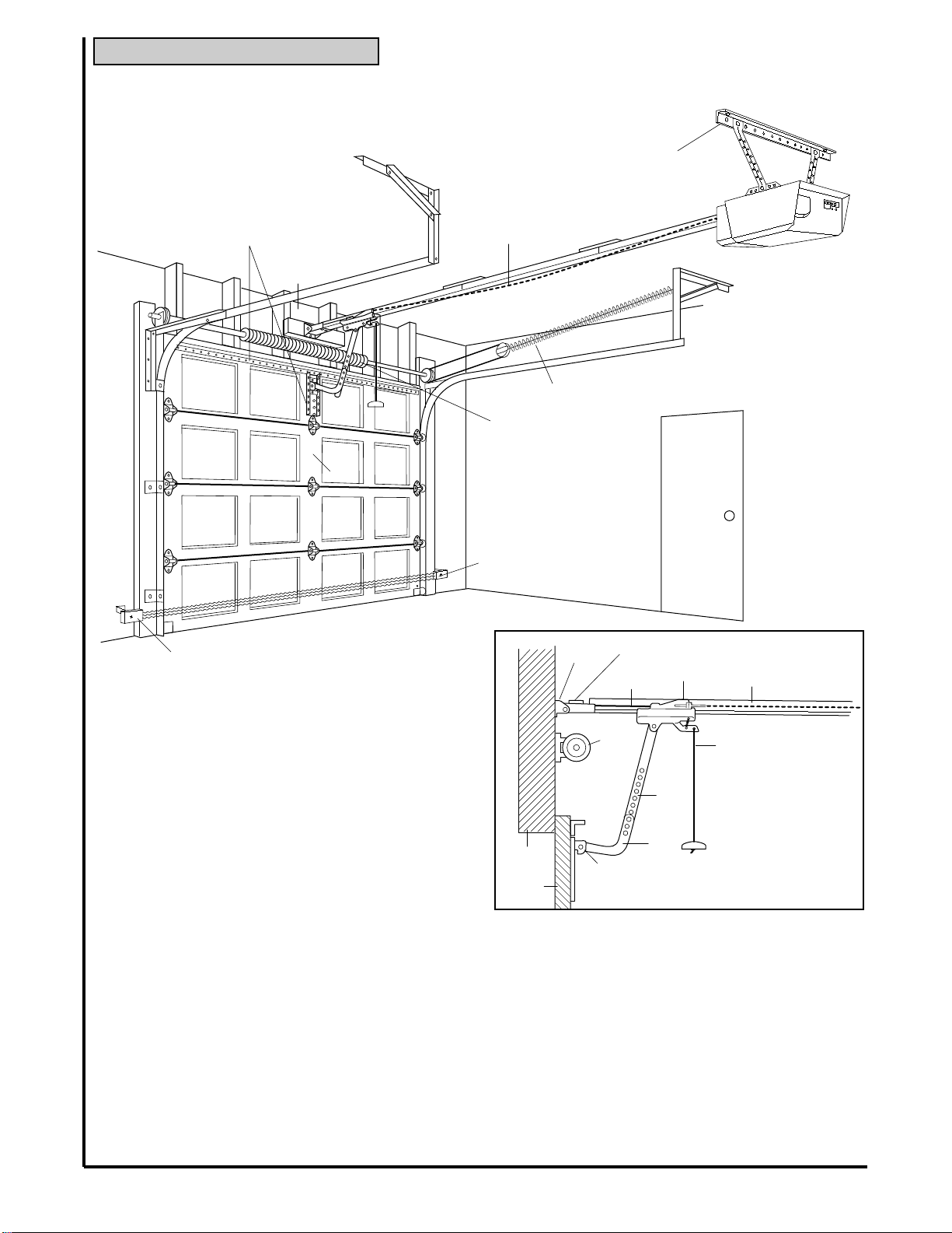
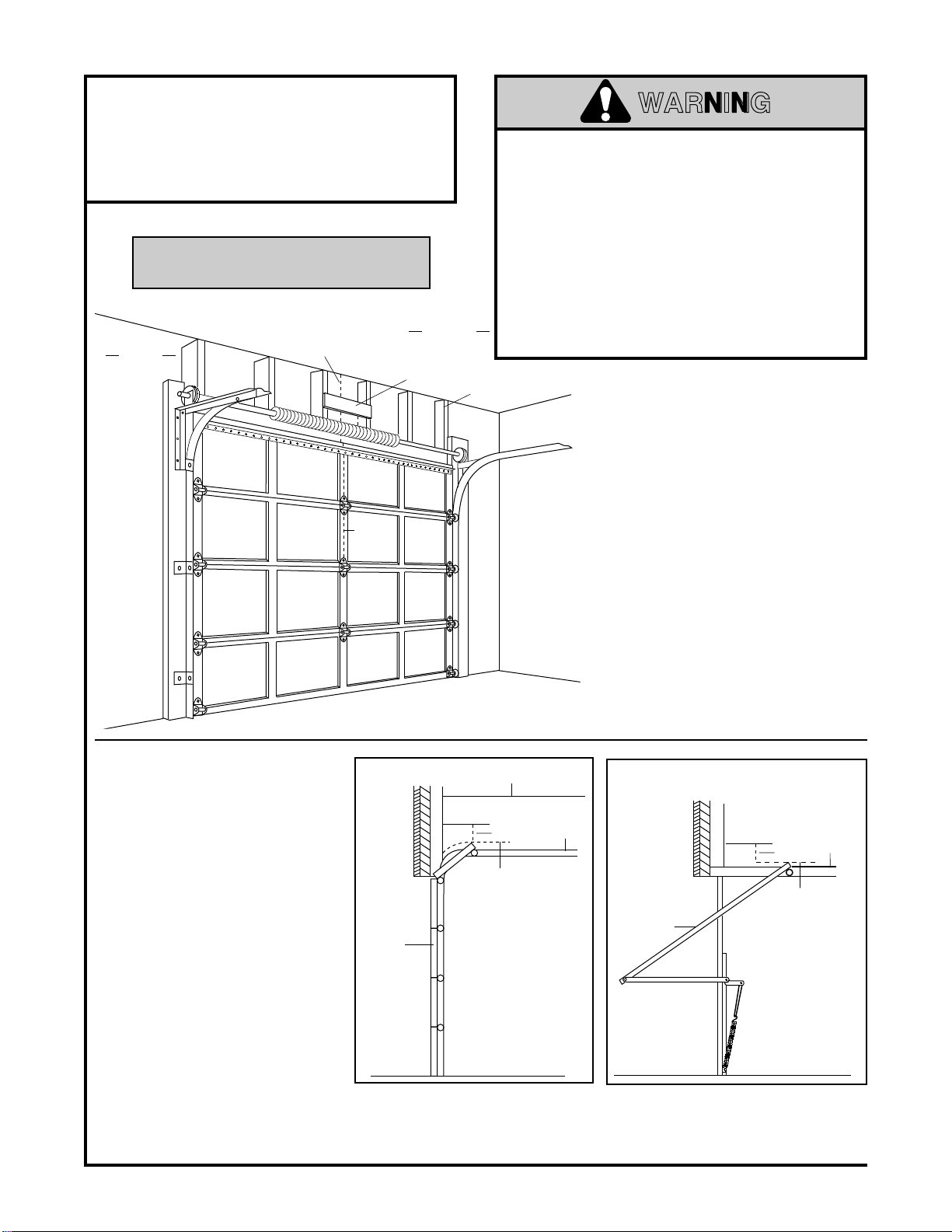
Illustration of sectional door installation .....................4
Illustration of one-piece door installation...................5
Carton inventory..........................................................6
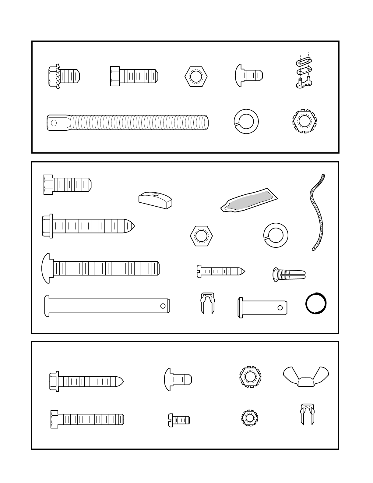
Hardware inventory.....................................................7
Assembly section - pages 8 – 11
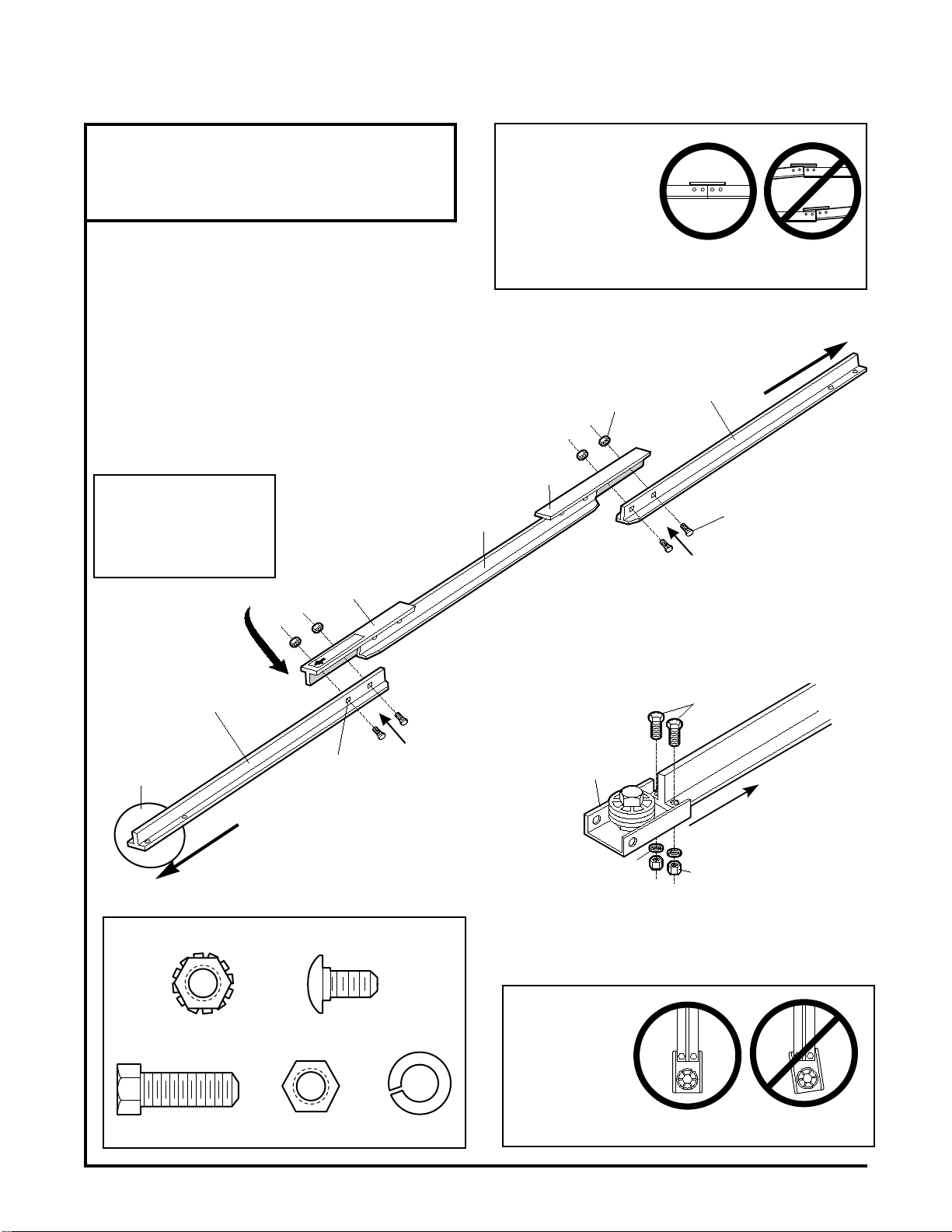
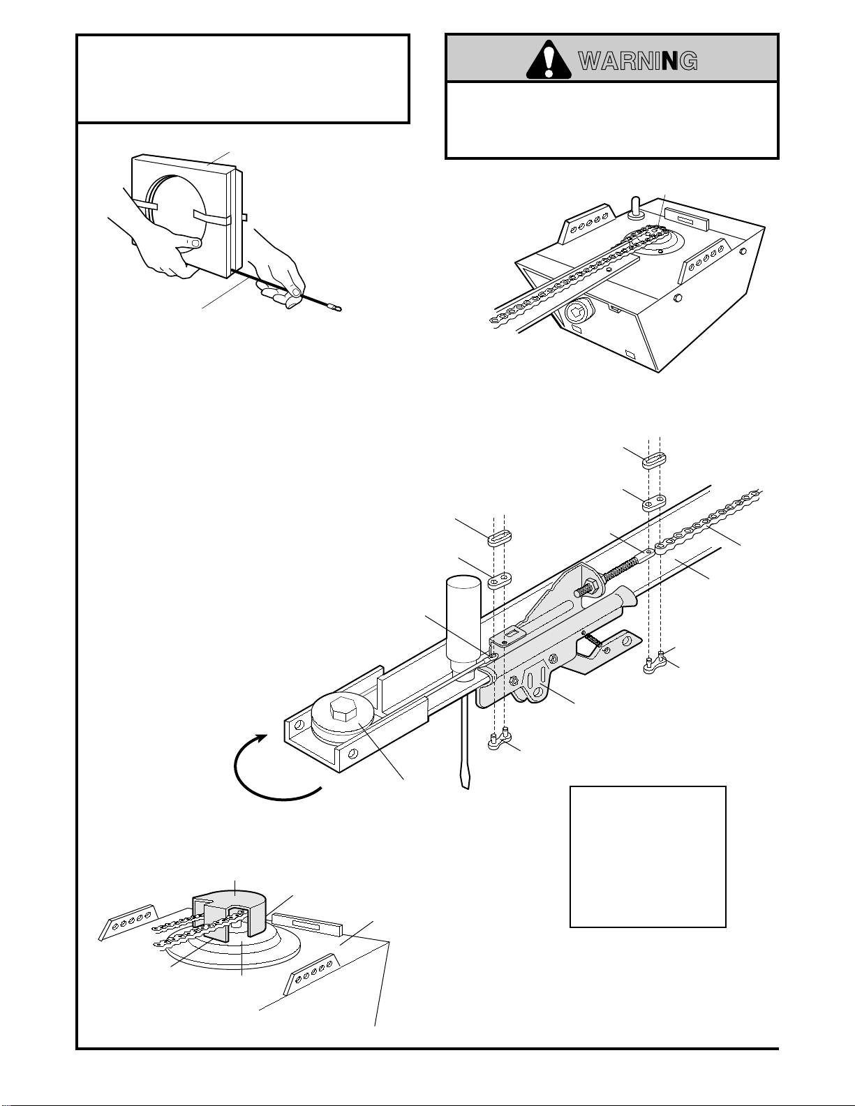
Assemble T-rail.........................................................8
Attach cable pulley bracket.......................................8
Install trolley ..............................................................9
Fasten T-rail to opener .............................................9
Install chain/cable ...................................................10
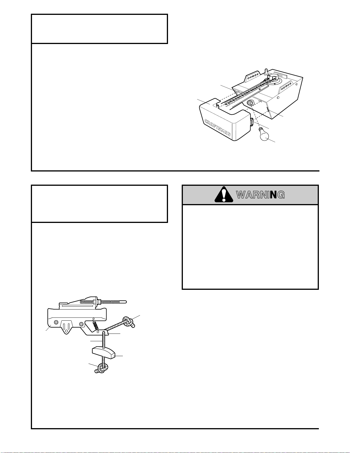
Attach sprocket cover.............................................10
Tighten the chain and cable...................................11
Installation section - pages 11 – 27
Installation safety instructions.................................11
Determine header bracket location
Sectional door.......................................................12
One-piece door.....................................................13
Install the header bracket.......................................14
Attach the T-rail to header bracket.........................15
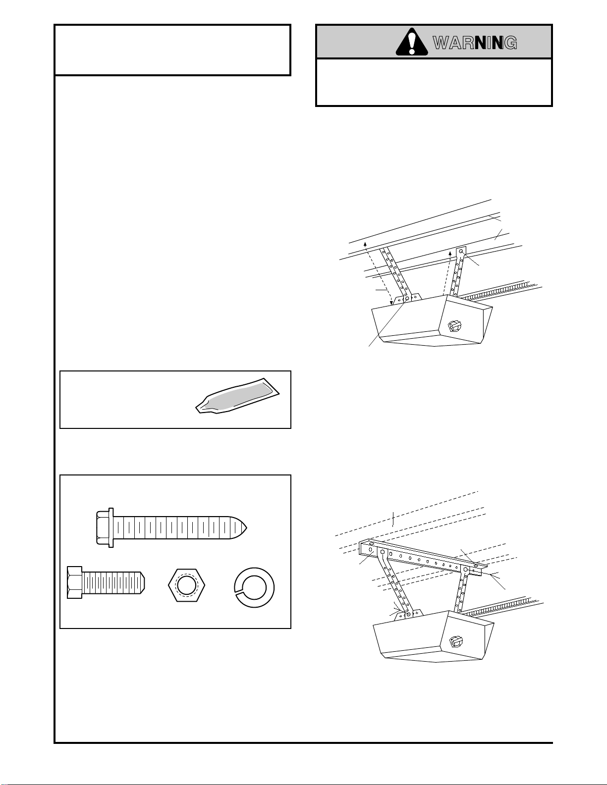
Position the opener.................................................16
Hang the opener.....................................................17
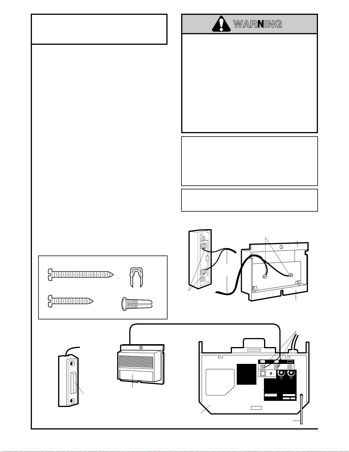
Install the wall control .............................................18
Contents Page
Install the light and lens.................................................19
Attach emergency release rope and handle.................19
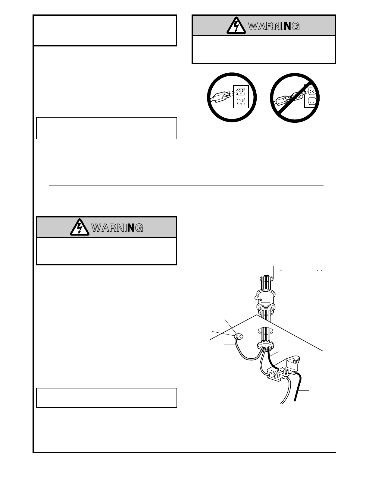
Electrical requirements..................................................20
Safety reversing sensor information .............................21
Install the safety reversing sensor...........................22, 23
Fasten door bracket (sectional door)............................24
Fasten door bracket (one-piece door)...........................25
Connect door arm to trolley (sectional door).................26
Connect door arm to trolley (one-piece door)...............27
Adjustment section - pages 28 – 30
Travel limit adjustments.................................................28
Force adjustments.........................................................29
Test the safety reversing sensor...................................30
Test the safety reverse system ....................................30
Operation safety instructions...........................................31
Care of your opener.........................................................31
Maintenance schedule ....................................................31
Operation of your opener ................................................32
Receiver and Transmitter Programming.........................33
Having a problem?....................................................34, 35
Repair parts, rail assembly..............................................36
Repair parts, installation..................................................36
Repair parts, opener assembly.......................................37
Accessories......................................................................38
Index ................................................................................39
How to order repair parts.................................................40
Maintenance agreement..................................................40
Warranty..........................................................................40
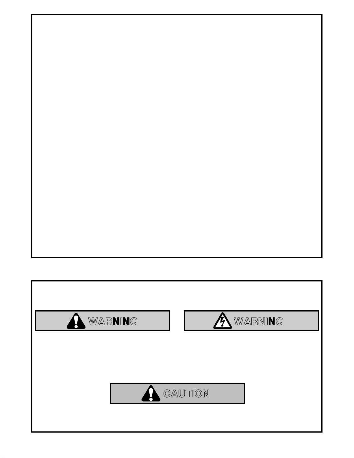
When you see these Safety Symbols on the following pages, they will alert you to the possibility of
serious injury or death
if you do not comply with the corresponding instructions. The hazard may
come from something mechanical or from electric shock.
Read the instructions carefully.
When you see this Safety Symbol on the following pages, it will alert you to the possibility of damage
to your garage door and/or the garage door opener if you do not comply with the corresponding
instructions.
Read the instructions carefully.
This garage door opener is designed and tested to offer safe service provided it is installed, operated,
maintained and tested in strict accordance with the safety instructions contained in this manual.
Mechanical Electrical
WARNING WARNING
CAUTION

Pliers
Wire Cutters
Claw Hammer
Hack Saw
Screwdriver Adjustable End Wrench
1/2" and 7/16" Sockets
and Wrench
Drill
Tape Measure
2
1
Stepladder
Pencil
3/16", 5/16", and
5/32" Drill Bits
Carpenter's
Level
During assembly, installation and adjustment of the opener, instructions will call for hand tools shown below.
3
SECTIONAL DOOR ONE-PIECE DOOR
An unbalanced garage door might not reverse
when required and someone under the door
could be seriously injured or killed.
If your garage door binds, sticks or is out of
balance, call for professional garage door
service.
Garage doors, door springs, cables,
pulleys, brackets and their hardware are under
extreme tension and can cause serious injury
or death.
Do not try to loosen, move or adjust
them yourself!
Ropes left on a garage door could cause
someone to become entangled and killed.
Remove all ropes connected to the door before
installing and operating the opener.
To avoid damage to the garage door and
opener, disable locks before installing and
operating the opener. Use a wood screw or nail
to hold locks in the "open" (unlocked) position.
Operation at other than 120V 60 Hz will cause
opener malfunction and damage.
CAUTION
WARNING
You'll Need Tools
Identify the type and height of your door and any
special conditions that exist and any additional
materials that may be required by referring to the lists
on page 4 or page 5.
Before you begin, complete the following test to
make sure your door is balanced, and is not
sticking or binding:
• Lift the door about halfway as shown. Release the
door. It should stay in place, supported entirely by
its springs.
• Raise and lower the door to see if there is any
binding or sticking.

4
Safety Reversing Sensor
Horizontal and vertical reinforcement
is needed for lightweight garage doors
(fiberglass, steel, aluminum, door with glass panels, etc.).
See page 24 for details.
Support bracket &
fastening hardware
is required.
See page 17.
Slack in Chain Tension
is Normal When
Garage Door is Closed
— — — — — — — —
Door Center
Header Wall
Safety
Reversing
Sensor
Floor must be level
across width of door
FINISHED CEILING
Extension Spring
Torsion Spring
Access Door
OR
Before you begin, survey your garage area to see whether any of the conditions below apply to your installation.
Based on your particular requirements, there are
several installation steps which might call for
materials and/or hardware not included in the carton.
• Step 1, page 12 - Look at the wall or ceiling above
the garage door. The header bracket
must
be
securely fastened to structural supports.
• Step 5, page 17 - Do you have a finished ceiling in
your garage? If so, a support bracket and
additional fastening hardware may be required.
• Safety reversing sensor, page 21 - Depending
upon garage construction, wood blocks may need
to be fastened to mounting locations before
sensors are installed.
• Step 10, page 22 - Alternate floor mounting of the
safety reversing sensor will require hardware not
provided.
• Step 11, page 24 - Do you have a steel, aluminum,
fiberglass or glass panel door? If so, horizontal
and vertical reinforcement is required.
• Look at the garage door where it meets the
floor. It must close on the floor all the way
across. Otherwise, the safety reverse system
may not work properly. See page 30. Floor or
door should be repaired.
Cable Pulley
Bracket
Header
Bracket Trolley
Straight
Door
Arm
Emergency
Release
Rope & Handle
Door Bracket
Garage
Door
Curved
Door
Arm
Garage
Door
Spring
Header
Wall
Cable Rail Assembly
Closed Position
SECTIONAL Door Installation
• An 8 foot high door will require Item No. 18754 Rail
Extension Kit. A 10 foot high door will require Item
No. 18753 Rail Extension Kit.
• The opener can be installed within 2 feet to the left
or right of the door center if there is a torsion spring
or center bearing plate in the way of the header
bracket or door bracket area.
If your door has
extension springs, the opener must be installed
in the center of the door.
See pages 12 and 24.
• Do you have an access door in addition to the
garage door? If not, Model 18752 Outside
Trolley Release is required. See page 38.
You may find it
helpful to refer
back to this page
as you proceed
with the installation
of your opener.

Safety
Reversing Sensor
FINISHED CEILING
Support bracket
& fastening hardware
may be required.
See page 17.
Slack in Chain Tension
is Normal When
Garage Door is Closed
Safety
Reversing
Sensor
Header
Wall
Access Door
Gap between floor and bottom of
door must not exceed 1/4"
Cable
Pulley Bracket
Header
Bracket
Trolley
Straight
Door
Arm
Emergency
Release
Rope & Handle
Door Bracket
Curved
Door
Arm
Header
Wall
Cable
T-rail
Garage
Door
Closed Position
5
Access
Door
Floor must be level
across width of door
Safety
Reversing Sensor
Header
Bracket
Cable
Pulley Bracket
Door
Bracket
Straight
Door
Arm
Curved
Door Arm
Trolley Chain
Emergency
Release
Rope & Handle
One-Piece Door with Track
Closed Position
Header
Wall
T-Rail
Garage
Door
Cable
Safety
Reversing
Sensor
Slack in Chain
Tension is Normal
When Garage Door is Closed
Before you begin, survey your garage area to see
whether any of the conditions below apply to your
installation.
Based on your particular requirements, there are
several installation steps which might call for materials
and/or hardware not included in the carton.You may
want to review these steps before beginning:
• Step 1, page 13 - Look at the wall or ceiling above
the garage door. The header bracket
must
be
securely fastened to structural supports.
• Step 5, page 17 - Do you have a finished ceiling in
your garage? If so, a support bracket and additional
fastening hardware (not supplied) may be required.
• Safety reversing sensor, page 21 - Depending on
garage construction, wood blocks may need to be
securely fastened to mounting locations before
sensors are installed.
• Step 10, page 22 - Alternate floor mounting of the
safety reversing sensor will require hardware that
is not provided.
• Step 11, page 25 - Generally, a one-piece door
does not require reinforcement. If your door is
lightweight, you can refer to the information
relating to sectional doors on page 24.
• Step 11, page 25 - Depending on your door's
construction, you might need additional mounting
hardware for the door bracket.
• Do you have an access door in addition to the
garage door? If not, Model 18752 Outside Trolley
Release is required. See page 38.
• The gap between the bottom of the garage
door and the floor cannot exceed 1/4".
Otherwise, the safety reverse system may not
work properly. See page 30. The floor or the door
should be repaired.
One-Piece Door without Track
ONE-PIECE Door Installation
You may find it helpful to refer back to this page as
you proceed with the installation of your opener.

6
Straight Door
Arm Section
Door Bracket Plate
Door Bracket
Curved Door
Arm Section
Safety Labels
and
Literature
Cable
Pulley Bracket
Chain and Cable
in Dispensing Carton
Header Bracket
UP
CEILING MOUNT ONLY
Safety Reversing Sensor
Mounting Bracket
With Square Holes (2)
"C" Wrap (2)
Safety Reversing Sensor
Mounting Bracket
With Slot (2)
Sprocket Cover
Safety Reversing Sensor (2)
(1) Sending Eye
(1) Receiving Eye
TO GARAGE DOOR
T-Rail
Center Section
T-Rail
End Sections
Hanging Brackets
2-Conductor
Bell Wire
White & White/Red
2-Conductor Bell Wire with Connector
White & White/Black (2 rolls)
Three-Function Transmitter
with Visor Clip (1) Lighted Console
Wall Control
Trolley
Light Lens
Single Function Transmitter
with Visor Clip (1)
Models 18803, 18830
Models 18805, 18814, 18850, 18851Models 18805, 18814, 18850, 18851
Lighted Push Button
Wall Control
Models 18803, 18830
Mini Three-Function
Transmitter
Model 18814, 18851
Touch Code Transmitter
Model 18814 only
Opener Carton Inventory
Your garage door opener is packaged in two cartons which contain all parts illustrated below. If anything is
missing, carefully check the packing material. Parts may be "stuck" in the foam. Hardware for assembly and
installation is shown on page 7.

7
Lock Washer
5/16" (4)
Nut 5/16"-18 (6)
Clevis Pin
5/16"x2-3/4" (1)
NOTICE
Handle
Insulated
Staples (10)
Rail Assembly Hardware Kit 41A3534
Installation Hardware Kit 41A3535
Dry Wall Anchors (2)
Clevis Pin
5/16"x1" (2)
Hex Screw
5/16"-18x7/8" (4)
Rope
Lock Nut
1/4"-20 (4)
Nut
5/16"-18 (5)
Washered Screw
5/16"-18x1/2" (2)
(mounted in opener)
Carriage Bolt
5/16"-18x2-1/2" (2)
Carriage Bolts
1/4"-20x1/2" (4)
Hex Screw
5/16"-18x7/8" (3)
Master Link (2)
Ring
Fastener (3)
Threaded
Trolley Shaft (1)
Screw
6ABx1" (2)
Lock Washer 5/16" (6)
Lag Screw
5/16"-18x1-7/8" (4)
Lock Nut
1/4"-20 (4)
Carriage Bolts
1/4"-20x1/2" (4)
Safety Reversing Sensor
Installation Hardware Kit 41A4116
Hex Screw
1/4-20x1-1/2" (2) Screw
#10-32x3/8" (4) Lock Nut
#10x32 (4)
Wing Nut (2)
Insulated
Staples (20)
Rail Grease
Lag Screw
1/4x1-1/2" (4)
Group all hardware found in all packages contained in the rail and opener cartons into
the three kits illustrated below.

8
Assembly Step 1
Assemble the T-rail & Attach
the Cable Pulley Bracket
• Align the 3 T-rail sections on a flat surface exactly
as shown. The end sections are identical. Make
sure the "arrow label" on the center section is
pointing toward the door.
• Insert the carriage bolts so the square bolt necks
seat in the square holes in the T-rail end sections
and pass through the round holes in T-rail center
section. Assemble lock nuts, ensure alignment and
tighten.
T-rail
(Center Section)
1/4'' Lock Nut
T-RAIL FRONT
(TO DOOR)
Cable pulley bracket
attaches to FRONT
END of T-rail
T-rail
(End Section)
T-RAIL BACK
(TO OPENER)
T-rail
(End Section)
Carriage Bolt
1/4"-20x1/2"
Brace
Brace
Square Carriage
Bolt Holes
TO GARAGE DOOR
Rail Bracket & T-rail Must Be A
Lock Washer
5/16" Nut
5/16"
Make sure bolt necks are
seated in the square
holes and rails are
aligned before you
tighten lock nuts. (See
right and wrong views).
Improper assembly can
cause jerky trolley
operation, noise and/or
nuisance door reversals.
To avoid installation difficulties, do not run the garage door opener until instructed to do so.
Assembly Section: Pages 8 – 11
Right Wrong
If T-rail is not assembled
EXACTLY as shown,
trolley will not travel
smoothly along length of
rail or it will hit against
the nuts.
Hex Screws
5/16"-18x7/8"
Cable Pulley
Bracket
Rail Bracket & T-rail Must Be Aligned
Lock Washer
5/16" Nut
5/16"
Right Wrong
When tightening
the screws, be
sure to keep
bracket parallel
to the rail.
Otherwise, the
rail may bow
when opener is
operated.
Lock Nut
1/4"-20 Carriage Bolts
1/4"-20x1/2"
Hex Screw
5/16"-18x7/8" Nut
5/16"-18 Lock Washer
5/16"
Hardware Shown Actual Size • Position the cable pulley bracket on the front end of the
T-rail as shown. Fasten securely with the hardware.

Assembly Step 2
Install the Trolley on the T-rail
• Place the opener on packing material to protect
the cover. For convenience, put a support under
the cable pulley bracket.
• Remove the (2) 5/16"-18x1/2" washered screws
mounted in the top of the opener.
• Align the holes in the back section of the T-rail with
the holes in the opener.
• Fasten the rail with the (2) washered screws
previously removed. Tighten securely.
Remember to use only these screws!
Any other
screws will cause serious damage to the opener.
• Insert a 5/16"-18x7/8" hex screw into the trolley
stop hole in the T-rail as shown. Tighten securely
with a 5/16" lock washer and nut. This screw limits
trolley travel in the UP direction.
Washered Screw
5/16"-18x1/2"
T-rail
(Back Section)
Trolley
Stop Hole
Nut
5/16"-18
Hex Screw
5/16"-18x7/8"
Lock Washer
5/16"
Use Only This
Type and Size
Screw
Temporary Stop
Screwdriver
TO GARAGE DOOR
Trolley
Trolley
Threaded
Shaft
Lock Washer
5/16"
Outer Nut
5/16"
Inner Nut
5/16"
Trolley
9
• Attach the trolley threaded shaft to the trolley with
the lock washer and nuts as shown.
• As a temporary stop, insert a screwdriver into the
hole in the front end of the T-rail.
• Slide the trolley assembly along the rail to the
screwdriver stop.
If trolley hits against the nut on the T-rail, the
bolts and nuts were attached from the wrong
side and must be repositioned. Review Step 1.
Assembly Step 3
Fasten the T-rail to the Opener
To fasten rail, use only those screws mounted
in the top of the opener. Any other screws will
cause serious damage to the opener.
Hardware Shown
Actual Size
Lock Washer
5/16" Nut
5/16"-18
Nut
5/16"-18 Lock Washer
5/16"
Hex Screw
5/16"-18x7/8"
Hardware Shown Actual Size
WARNING

Assembly Step 4
Install the Chain/Cable
& Attach the Sprocket Cover
Sprocket
Cover
Mounting
Plate
Front Tab Slot
Back Tab Slot
Top of Opener
Opener
Sprocket
10
To attach the sprocket cover:
• Insert the back tab in the opener slot. Squeeze the
cover slightly and insert the front tab in the slot on
the mounting plate.
Leave Chain and Cable
Inside Dispensing
Carton to Prevent Kinking.
Dispensing Carton
Keep Chain and Cable
Taut When Dispensing
Front Tab
Cable
Pulley
Cable
Loop
Master
Link Bar
Th
Master
Link Cap
Master Link
Clip-On Spring
Install Chain and Cable
In This Direction
• Detach the cable loop from the carton and fasten it
to the trolley with a master link from the hardware
bag. See master link procedure, Figure 1.
• With the trolley against the screwdriver, dispense
the cable around the pulley.
• Proceed back around the opener sprocket, Figure 2.
Be sure sprocket teeth engage the chain. Continue
forward to the trolley threaded shaft, Figure 3.
• Use the second master link to connect the chain to
the flat end of the shaft. Check to make sure
the chain is not twisted.
• Remove the screwdriver.
Keep Chain and Cable
Taut When Dispensing
Cable
Pulley
Cable
Loop
Master
Link Bar
Master Link
Clip-On Spring
Trolley
T-rail
Pin
Pin Notch
Chain
Flat End
of Trolley
Threaded Shaft
Master
Link Cap
Master
Link Cap
Master Link
Clip-On Spring
Install Chain and Cable
In This Direction
Master Link Procedure:
Push pins of master link
bar through cable loop and
hole in front end of trolley.
Push cap over pins and
into notches. Slide clip-on
spring over cap and into
notches until both pins are
securely locked.
Figure 2
Figure 3
Figure 1
Serious injury can result if fingers become
entangled in moving opener sprocket. Attach
sprocket cover securely. Never operate opener
while your hand is near the opener sprocket.
WARNING

• Spin the inner nut and lock washer down the
threaded shaft, away from the trolley.
• To tighten the chain, turn outer nut in the direction
shown. As you turn the nut, keep the chain
from twisting.
• When the chain is approximately 1/2" above the
base of the T-rail at its midpoint, re-tighten the
inner nut to secure the adjustment.
Sprocket noise can result if chain is either too
loose or too tight.
When installation is complete, you may notice some
chain droop with the door closed. This is normal. If
the chain returns to the position shown when the
door is open,
do not re-adjust the chain.
NOTE: During future maintenance,
ALWAYS
pull the emergency release handle to disconnect
trolley before adjusting chain.
Lock
Washer
To Tighten Outer Nut
Inner Nut
Trolley
Chain
Base of T-rail
1/2"
To Tighten
Inner Nut
Outer Nut
Assembly Step 5
Tighten the Chain & Cable
IMPORTANT INSTALLATION INSTRUCTIONS
To reduce the risk of severe injury or death to persons:
1. READ AND FOLLOW ALL INSTALLATION INSTRUCTIONS
2. Install only on a properly balanced and lubricated garage door.
An improperly balanced door
could result in severe injury or death.
Repairs to cables, spring assemblies and other hardware
must be made by a professional service person before installing opener.
3. Disable all locks and remove all ropes connected to the garage door before installing the opener.
Ropes connected to a garage door can cause entanglement and death.
4. If possible, install door opener 7 feet or more above floor with the manual release handle
mounted 6 feet above the floor.
5. Do not connect the opener to power source until instructed to do so.
6. Locate the Wall Control within sight of the door at a minimum height of 5 feet where small
children cannot reach and away from all moving parts of the door.
7. Install the User Safety Instruction Label on the wall adjacent to the control button and the
Maintenance Instruction Label in a prominent location on the inside of the garage door.
8. Upon completion of the installation, the door must reverse when it comes in contact with a 2x4
laid flat on the floor.
9. Do not wear watches, rings or loose clothing while installing or servicing an opener. Jewelry or
loose clothing can be caught in the mechanism of the garage door or the opener.
11
You have now finished assembling your garage door opener. Please read the following
warnings before proceeding to the installation section:
WARNING WARNING

• Open your door to the highest
point of travel as shown. Draw
an intersecting horizontal line
on the header wall 2" above
the high point. This height will
provide travel clearance for the
top edge of the door.
Door clearance brackets are
available for sectional doors
when headroom clearance is
less than 2". See accessory
page 38.
Header
Wall
Ceiling
Track
Highest Point
of Travel
Door
2"
12
Proceed to Step 2, page 14.
Door
Track
Header
Wall
Highest Point
of Travel
2"
Vertical
Guideline
Finished
Ceiling
Vertical
Guideline
Header
Wall 2x4 Structural
Supports
SECTIONAL Door and
ONE-PIECE Door With Track
• Close the door and mark the inside
vertical centerline of the garage door.
• Extend the line onto the header wall
above the door.
Remember, you can fasten the
header bracket within 2 feet of the
left or right of the door center
only
if
a torsion spring or center bearing
plate is in the way; or you can attach
it to the ceiling (refer to page 14)
when clearance is minimal.
If you need to install the header bracket
on a 2x4 (on wall or ceiling), use lag
screws (not supplied) to securely fasten
the 2x4 to structural supports.
Installation Section: Pages 12 – 27
Sectional door
with curved track One-piece door
with horizontal track
Installation Step 1
Determine Header Bracket Location
Installation procedures vary according to
garage door types. Follow the instructions
which apply to your door.
If the header bracket is not rigidly fastened to
a structural support on the header wall or
ceiling, the safety reverse system may not
work properly (see page 30).
The door might
not reverse when required, and could cause
serious injury or death.
The garage door springs, cables, pulleys,
brackets and their hardware are under extreme
tension.
Do not attempt to loosen, move or
adjust them yourself. Serious personal injury or
death could result.
Call for professional garage
door service.
WARNING

Door
Highest Point
of Travel
Header
Wall
Pivot
Distance
Header Wall Vertical
Centerline
Vertical
Centerline of
Garage Door
2x4
Unfinished
Ceiling
Structural Supports
2x4
OPTIONAL CEILING MOUNT
FOR HEADER BRACKET
• Close the door and mark the
inside vertical centerline of
your garage door. Extend the
line onto the header wall
above door.
If headroom clearance is
minimal, you can install the
header bracket on the ceiling.
See page 14.
•
If you need to install the
header bracket on a 2x4 (on
wall or ceiling), use lag screws
(not supplied) to securely
fasten the 2x4 to structural
supports as shown.
EXAMPLE
Distance from top of door
(at highest point of travel) to floor...........................92"
Actual height of door.............................................-88"
Remainder................................................................4"
Add.........................................................................+8"
Bracket height on header wall..............................=12"
(Measure UP from top of CLOSED door.)
Proceed to Step 2, page 14.
13
Header Wall
Highest Point
of Travel
Door
Distance
Jamb
Hardware
ONE-PIECE Door Without Track
• Open your door to the highest point of travel as
shown. Measure the distance from the top of the
door to the floor. Subtract the actual height of the
door. Add 8" to the remainder. (See Example).
• Close the door and draw an intersecting horizontal
line on the header wall at the determined height.
If the total number of inches exceeds the height
available in your garage, use the maximum
height possible, or refer to page 14 for ceiling
installation.
One-piece door without track
jamb hardware One-piece door without track
pivot hardware
Read the Safety Instructions on page 12. They also apply to doors without tracks.

UP
CEILING MOUNT ONLY
Ceiling Mounting Holes
The nail hole is for positioning only.
You must use lag screws to mount
the header bracket.
UP
Lag Screws
5/16"x18x1-7/8"
Garage
Door
Vertical
Center Line
Header
Wall
Finished
Ceiling
Header
Bracket
6" Maximum
Vertical
Center Line
Door
Spring
14
You can attach the header bracket either to the
wall above the garage door, or to the ceiling.
Follow the instructions which will work best for
your particular requirements.
Fasten the Header Bracket to the Wall
• Center the bracket on the vertical guideline with
the bottom edge of the bracket on the horizontal
line as shown (with the arrow pointing toward the
ceiling).
• Mark either set of bracket holes (do not use the
holes designated for ceiling mount). Drill 3/16" pilot
holes and fasten the bracket securely to structural
support with the hardware provided.
• Extend the vertical guideline onto the ceiling as
shown.
• Center the bracket on the vertical mark, no more
than 6" from the wall. Make sure the arrow is
pointing toward the wall. The bracket can be
mounted flush against the ceiling when clearance
is minimal.
• Mark holes designated for ceiling mount only. Drill
3/16" pilot holes and fasten bracket securely to
structural support with the hardware provided.
Fasten the Header Bracket to the Ceiling
Installation Step 2
Install the Header Bracket
Lag Screw
5/16"-18x1-7/8"
Hardware Shown Actual Size
Lag Screws
5/16"x18x1-7/8"
Highest
Point of Travel
(of Garage Door)
Vertical
Center
Line
Header
Wall
Garage
Door
UP
CEILING MOUNT ONLY
Wall
Mounting Holes
Optional
Wall Mounting
Holes
The nail hole is for positioning
only. You must use lag screws to
mount the header bracket.
UP
CEILING MOUNT ONLY
Door
Spring
Header
Bracket
2x4
Structural
Support
Vertical
Center
Line

Header
Bracket
Cable
Pulley
Bracket
Temporary
Support
Header Wall
Garage
Door
T-rail
Clevis Pin
5/16"x2-3/4 "
Ring Fastener
Header Bracket
Cable
Pulley
Bracket
T-rail
• Position the opener on the garage floor below the
header bracket. Use packing material as a
protective base.
If the door spring is in the way you'll need help.
Have someone hold the opener securely on a
temporary support to allow the T-rail to clear the
spring.
• Position the cable pulley bracket against the header
bracket.
• Align the bracket holes and join with a clevis pin as
shown.
• Insert a ring fastener to secure.
15
Installation Step 3
Attach the T-rail to the Header Bracket
Clevis Pin
5/16"x2-3/4" Ring Fastener
Hardware Shown Actual Size

Installation Step 4
Position the Opener
Follow instructions which apply to your door
type as illustrated. To prevent damage to steel, aluminum,
fiberglass or glass panel doors, do not rest the
opener on the door without using a 2x4.
SECTIONAL Door & ONE-PIECE Door with Track
A 2x4 laid flat is convenient for setting an ideal
door-to-T-rail distance.
• Raise the opener onto a stepladder.
You will need help at this point if the ladder is
not tall enough.
• Open the door all the way and place a 2x4 laid flat
on the top section beneath the T-rail.
If the top panel hits the trolley when you raise
the door, pull down on the trolley release arm to
disconnect the inner and outer sections. The
trolley can remain disconnected until Step 12 is
completed.
T-rail 2x4
Door
Stepladder
ONE-PIECE Door without Track
• With the door fully open and parallel to the floor,
measure the distance from the floor to the top of
the door.
• Using a stepladder as a support, raise the opener
to the same distance as the door from the floor (it
will be at a slight angle as shown).
• The top of the door should be level with the top of
the opener. Do not position the opener more than
2" above this point.
Top of Opener
Header
Bracket
Stepladder
Top of Door
16
CAUTION
Trolley
Trolley
Release Arm

Installation Step 5
Hang the Opener
Two representative installations are shown.
Yours may be different. Hanging brackets should
be angled, Figure 1, to provide rigid support. On
finished ceilings, Figure 2, attach a sturdy metal
bracket to structural supports before installing the
opener. The bracket and fastening hardware are not
supplied.
• Measure the distance from
each
side of the opener
to the structural support.
• Cut both pieces of the hanging bracket to required
lengths.
• Drill 3/16" pilot holes in the structural supports.
• Attach one end of each bracket to a support with
5/16"x1-7/8" lag screws.
• Fasten the opener to the hanging brackets with
5/16"-18x7/8" screws, lock washers and nuts.
• Check to make sure the T-rail is centered over the
door (or in line with the header bracket if the
bracket is not centered above the door).
• Remove the 2x4. Operate the door manually. If the
door hits the rail, raise the header bracket.
Grease the top and underside
of the rail surface where
the trolley slides with rail
grease.
Measure
Distance
Lag Screws
5/16"x1-7/8"
Bracket
(Not Supplied)
Lag Screws
5/16"x1-7/8"
(Not Supplied)
5/16"-18x7/8" Screw
5/16" Lock Washer
5/16"-18 Nut
— FINISHED CEILING —
Structural
Supports
5/16"-18x7/8" Screw
5/16" Lock Washer
5/16"-18 Nut
Hidden
Support
5/16"-18x7/8" Screw
5/16" Lock Washer
5/16"-18 Nut
17
The opener could fall and injure someone if it
is not properly secured.
Fasten the opener
securely to structural supports of the garage.
Figure 1
Figure 2
Lag Screw
5/16"-18x1-7/8"
Hex Screw
5/16"-18x7/8" Nut 5/16"-18 Lock Washer 5/16"
Hardware Shown Actual Size
WARNING

Installation Step 6
Install the Wall Control
18
Children operating or playing with a garage
door opener can injure themselves or others.
The garage door could close and cause serious
injury or death.
Install the Wall Control (or any additional push
buttons) out of the reach of children and away
from all moving parts of the door and door
hardware,
but where the garage door is visible.
Do not allow children to operate the push
button(s) or the remote control transmitter(s).
A moving garage door could injure someone
under it.
Activate the opener only when the
door is properly adjusted, you can see it clearly,
and there are no obstructions to door travel.
Terminal Screws
2-Conductor
Bell Wire
Antenna
Back Panel
of Opener
Install Wall Control or Lighted Push Button
Sears Front to Back
3/30/92 - 4/2/92
RED WHITE
Terminal Screws Top Installation
Flange
Bottom Installation
Flange
Lighted Push Button
Wall Control Lighted Console Wall Control
Lighted Push Bar
WHT
2
RED
1
Opener
Terminal Screws
Lighted
Push Button
KG KG
M.D.C. CERT. NO.
1
3
9
75
132C2105-1
WARNING: To reduce the risk of severe injury
or death by entrapment, when adjusting either
the force or limits of travel controls ensure that
the door reverses on a 1 inch object (or a 2 x 4
board laid flat). See instructions for proper
adjustment procedure.
This device complies
with FCC Rules Part
15. Operation of this
device is subject to the
following conditions:
1. This device may
not cause harmful
interference. 2. This
device must accept
any interference
that may be received,
including interference
that may cause
undesired operation.
PART NO: NºDE PIÈCE:
D.O.C. CERT. NO. DATE:
Sears Roebuck & Co.
Sears Canada Inc., Toronto
Assembled in Mexico - Assemblé du Mexique
PAT. #RE29,525; 4,750,201; 4,806,930 Other Patents Pending.
AVERTISSEMENT: Pour réduire les risques de
blessures mortelles par happement, après tout
réglage de la force de déclenchement ou des
seuils de fin de course s'assurer que le sens de
la course s'inverse lorsque la porte entre en
contact avec un object de 13 mm (1 po) de
hauteur (ou un madrier de 2 x 4 de section, à
plat) posé sur le sol. Effectuer les reglages
selon les procédures décrites dans la notice.
1
3
9
75
23
TO PROGRAM RECEIVER CODE
FOR EACH REMOTE CONTROL
1. Press and HOLD remote control
transmitter push button.
2. Press receiver code button. The opener
light will flash once.
3. Release transmnitter button. Opener
has learned code.
TO ERASE ALL RECEIVER CODES
1. Press and HOLD receiver code button.
Green indicator light alongside will turn
ON.
2. When light turns OFF (about 6
seconds) ALL codes are erased from
opener memory.
1
12
• Strip 1/4" of insulation from one end of the bell wire;
connect the wire to the two screw terminals on the
back of the Wall Control: white to 2, white/red to 1.
• Locate the Wall Control within sight of the door
at a minimum height of 5 feet where small
children cannot reach, and away from all
moving parts of the door and door hardware.
Fasten the Lighted Push Button Wall Control
securely with 6ABx1-1/2" screws. The console
style uses 6ABx1" screws. If installing into drywall,
drill 5/32" holes and use the anchors provided.
• Run the bell wire up the wall and across the ceiling
to the opener. Use insulated staples to secure the
wire in several places. Be careful not to pierce the
wire with a staple, thereby resulting in a short.
• Receiver terminals and the antenna are located on
the back panel of the opener. Position the antenna
wire as shown.
• Then connect the bell wire to the opener terminal
screws: white to 2; white/red to 1.
• Remember to affix the User Safety Instruction
label to the wall near the Wall Control, and the
Maintenance Instruction label in a prominent
location on the inside of the garage door.
If the label adhesive will not adhere to your garage
wall surface (or becomes loose with time) use tacks
to secure the label alongside the control button.
Page 32 explains how to operate the opener using
the lighted push bar or button.
Do NOT connect the power and operate the
opener at this time.
The trolley will travel to the
full
open
position but will not return to the
close
position until the sensor beam is
connected and properly aligned.
See Safety Reversing Sensor instructions
beginning on page 21.
Dry Wall Anchors
Insulated Staples
6ABx1" Screw
Lighted Console Wall Control
6ABx1-1/2" Screw
Lighted Push Button Wall Control
Hardware Shown Actual Size
Outdoor Key Switch Accessory Connections:
To opener terminal screws: white to 2;white/red to 1
WARNING

Lens Guide
Lens Slot
75 Watt Max.
Light Bulb
Lens Tab
Light Lens
Install the light
• Install a 75 watt maximum light bulb in the socket.
The light will turn ON and remain lit for
approximately 4-1/2 minutes when power is
connected. Then the light will turn OFF.
• If the bulb burns out prematurely due to vibration,
replace it with a "Garage Door Opener" bulb.
Install the lens
• Apply slight pressure on the sides of the lens and
slide the tabs into the slots in the end panel.
• Reverse the procedure to remove the lens.
Installation Step 7
Install the Light and the Lens
Installation Step 8
Attach the Emergency Release
Rope and Handle
Do not use the red handle to pull the door
open or closed.
The rope knot could become
untied and you could fall.
Use the emergency
release only to disengage the trolley and, if
possible, only when the door is closed.
Garage doors are heavy. If the door is open
when the handle is pulled, the door could
close inadvertently if it is not properly
balanced. Serious injury may result to persons
under the door. Make sure the doorway is clear
of persons and obstructions before pulling
handle when door is open.
• Thread one end of the rope through the hole in the
top of the red handle so "NOTICE" reads right side
up as shown. Secure with an overhand knot.
The knot should be at least 1" from the end of the
rope to prevent slipping.
• Thread the other end of the rope through the hole in
the release arm of the outer trolley.
• Adjust rope length so the handle is 6 feet above the
floor. Secure with an overhand knot.
If it is necessary to cut the rope, heat seal the cut
end with a match or lighter to prevent unraveling.
Trolley
NOTICE
Overhand
Knot
Emergency
Release Handle
Rope
Overhand
Knot
Trolley
Release Arm
19
WARNING

To reduce the risk of electric shock, your garage
door opener has a grounding type plug with a third
grounding pin. This plug will
only
fit into a grounding
type outlet.
If the plug doesn't fit into the outlet you have,
contact a qualified electrician to install the proper
outlet.
RIGHT WRONG
Installation Step 9
Electrical Requirements
Ground Tab
Green Ground
Screw
Ground Wire
Black
Wire
Permanent wiring
connection
White Wire
Black
Wire
• To make a permanent connection through the 7/8"
diameter hole in the top of the opener (according
to local code):
• Remove the opener cover screws and set the
cover aside.
• Remove the attached 3-prong cord.
• Connect the black (line) wire to the screw on the
brass terminal; the white (neutral) wire to the
screw on the silver terminal; and the ground wire
to the green ground screw.
The opener must be
grounded.
• Reinstall the cover.
20
To prevent electrocution or fire,
installation
and wiring must be in compliance with local
electrical and building codes.
Permanent Wiring Connection
Right Wrong
To avoid installation difficulties,
do not run the opener at this time.
To avoid installation difficulties,
do not run the opener at this time.
• Do not change the plug in any way.
• Do not use a 2-wire adapter.
• Do not use an extension cord.
If permanent wiring is required by your local code, refer to the following procedure:
WARNING
WARNING
To prevent electrocution, remove power from
the garage door opener
and
from the circuit
you plan to use for the permanent connection.
This manual suits for next models
11
Table of contents
Other Crafstman Garage Door Opener manuals
Popular Garage Door Opener manuals by other brands

Chamberlain
Chamberlain Whisper Drive Security+ HD900D owner's manual

O&O
O&O ZEROQUATTRO 180 Installation, use and maintenance

MyGate
MyGate MYASTER NEW installation manual

Chamberlain
Chamberlain Elite 3585CS owner's manual

Merlin
Merlin Tiltmaster MT100EVO Installation and operating instructions

BFT
BFT LUX Installation and user manual